Audio Gear Obsession DYNAMICENGINE User manual

DYNAMICENGINE
User’s Manual
Audio Gear Obsession

Contents
1 Warranty 3
2 Device Overview 3
3 Block Scheme 4
4 Input & Output Section 5
4.1 InputJacks ............................. 5
4.2 OutputJacks ............................ 5
4.3 External Side-chain Jacks . . . . . . . . . . . . . . . . . . . . . 5
5 Control Section 7
5.1 Input Gain & Threshold Controls . . . . . . . . . . . . . . . . . . 7
5.2 Attack & Release Controls . . . . . . . . . . . . . . . . . . . . . 8
5.3 Ratio & Knee Control . . . . . . . . . . . . . . . . . . . . . . . . 9
5.4 Make Up & Mix Control . . . . . . . . . . . . . . . . . . . . . . . 10
5.5 External Side-chain Gain . . . . . . . . . . . . . . . . . . . . . . 11
5.6 Side-chain Cut-off Control . . . . . . . . . . . . . . . . . . . . . 12
5.7 Bypass & Stereo Link Control . . . . . . . . . . . . . . . . . . . . 12
6 Attenuation Led Bars 13
7 Power Connection 14
8 Specifications 15
List of Figures
1 DYNAMICENGINE Block Scheme . . . . . . . . . . . . . . . . . . 4
2 Input & Output Section . . . . . . . . . . . . . . . . . . . . . . . 5
3 Input Gain & Threshold Controls . . . . . . . . . . . . . . . . . . 7
4 Attack & Release Controls . . . . . . . . . . . . . . . . . . . . . 8
5 Ratio&KneeControl ........................ 9
6 Make Up & Mix Control . . . . . . . . . . . . . . . . . . . . . . . 10
7 External Side-chain Gain . . . . . . . . . . . . . . . . . . . . . . 11
8 Side-chain Cut-off Control . . . . . . . . . . . . . . . . . . . . . 12
9 Bypass & Stereo Link Control . . . . . . . . . . . . . . . . . . . . 12
10 Attenuation Led Bar . . . . . . . . . . . . . . . . . . . . . . . . 13
11 PowerConnection.......................... 14
2

1 Warranty
Audio Gear Obsession warrants this product to be free of defects and malfunctions
for a period of two years from the purchase date (i.e. the invoice date).
Malfunctions caused by the improper use of this device such as:
• wrong power supply connection
• usage with voltage above absolute maximim rating (see the Specification
section)
• any components removing
and any other malfunctions determined by Audio Gear Obsession to be caused
by improper user actions, will void the warranty. Standard service rate will apply.
Audio Gear Obsession do not accepts responsability for harm to people, animals,
objects and the environment caused by the improper use of this product.
2 Device Overview
DYNAMICENGINE is a dual mono compressor-limiter with stereo link.
This device is an ergonomic medium to compress signals inside and outside the
Eurorack format, making the connection between Eurorack and non-Eurorack
gear easier. Both compressors have adjustable Input Gain, Threshold, Attack,
Release, Ratio, Knee, Make Up, Mix, Bypass, Side-chain Filter and External Side-
chain Gain. The mono compressors can be linked using the stereo link control.
Input and output circuitry offers plug-and-play balanced and unbalanced con-
nections capabilities.
The engineering behind this module is pointed toward obtaining the lowest noise
and the best performance possible.
3
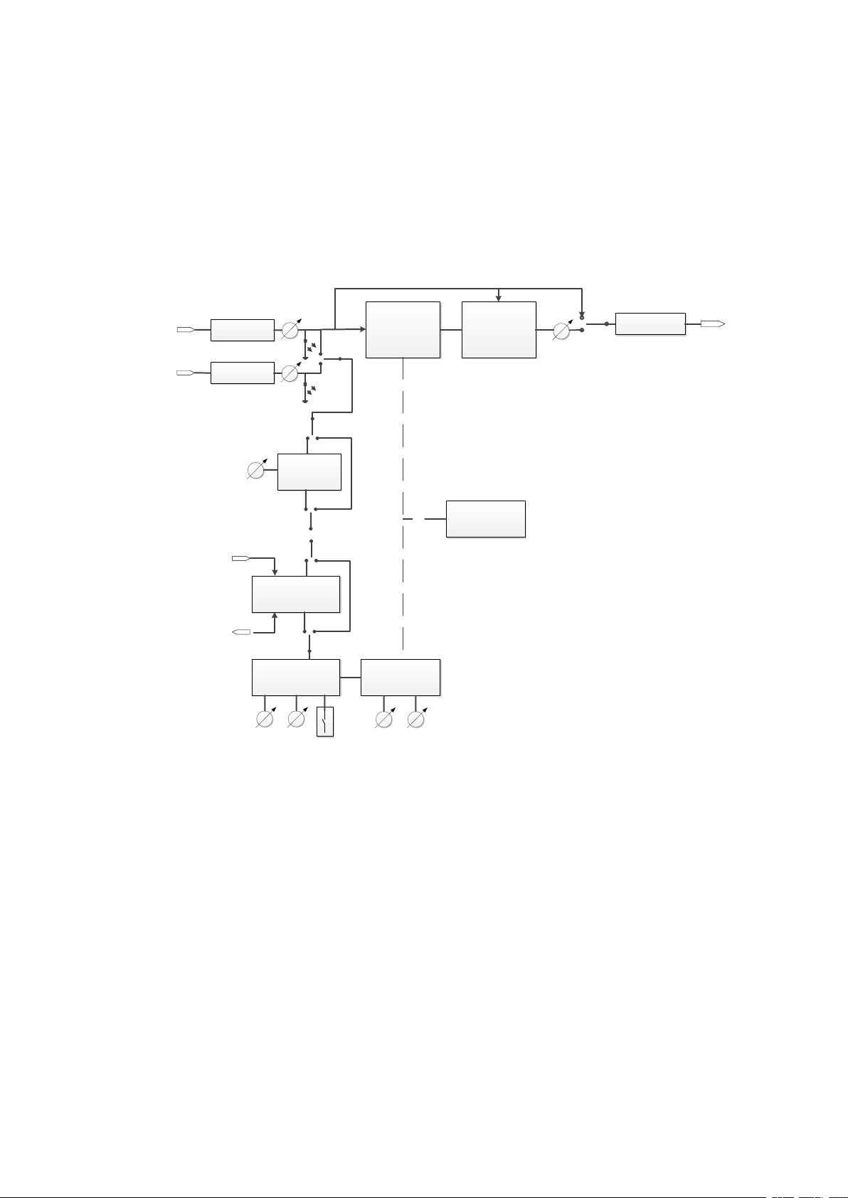
3 Block Scheme
The figure below shows the functional block scheme of DYNAMICENGINE.
INPUT STAGE
INPUT SIGNAL
INPUT STAGE
INPUT SIGNAL
SIDE CHAIN
HI-PASS
FILTER
STEREO LINK
FROM OTHER CHANNEL SIDECHAIN
THRESHOLD
STAGE
TIMING
STAGE
COMPRESSION
STAGE
MIXING
STAGE
OUTPUT STAGE
ATTENUATION
LED BAR
OUTPUT STAGE
TO OTHER CHANNEL THRESHOLD
SC. CUTOFF
GAIN
GAIN
GAIN BYPASS
THRESHOLD RATIO
KNEE ATTACK RELEASE
Figure 1: DYNAMICENGINE Block Scheme
4
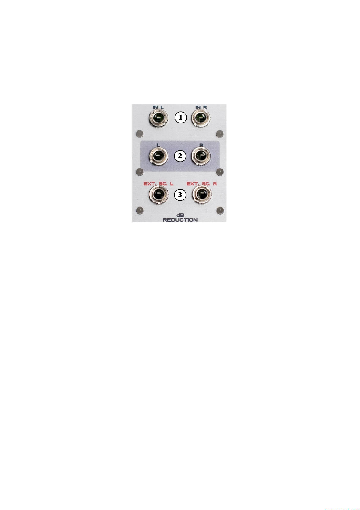
4 Input & Output Section
Figure 2: Input & Output Section
4.1 Input Jacks
DYNAMICENGINE features two 3.5 mm balanced Inputs Jacks (1). The balanced
inputs can be exploited to accomodate the interconnections between Eurorack
and non-Eurorack gear (e.g. API500, Rack 19”, Desktop...). Standard 3.5 mm
mono patch cables can be used. All inputs feature a led that monitors the signal
intensity after the Input Gain stage.
4.2 Output Jacks
DYNAMICENGINE features two 3.5 mm balanced Output Jacks. The balanced out-
puts can be exploited to accomodate interconnections between Eurorack and
non-Eurorack gear (e.g. API500, Rack 19”, Desktop...). Standard 3.5 mm mono
patch cables can be used. All outputs feature a led that monitors the signal
intensity after the Make Up stage.
4.3 External Side-chain Jacks
DYNAMICENGINE features two 3.5 mm balanced External Side-chain Jacks. The
balanced inputs can be exploited to accomodate interconnections between Eu-
rorack and non-Eurorack gear (e.g. API500, Rack 19”, Desktop...). Standard 3.5
5

mm mono patch cables can be used. All inputs feature a led that monitors the
signal intensity after the External Side-chain Gain stage.
6
5 Control Section
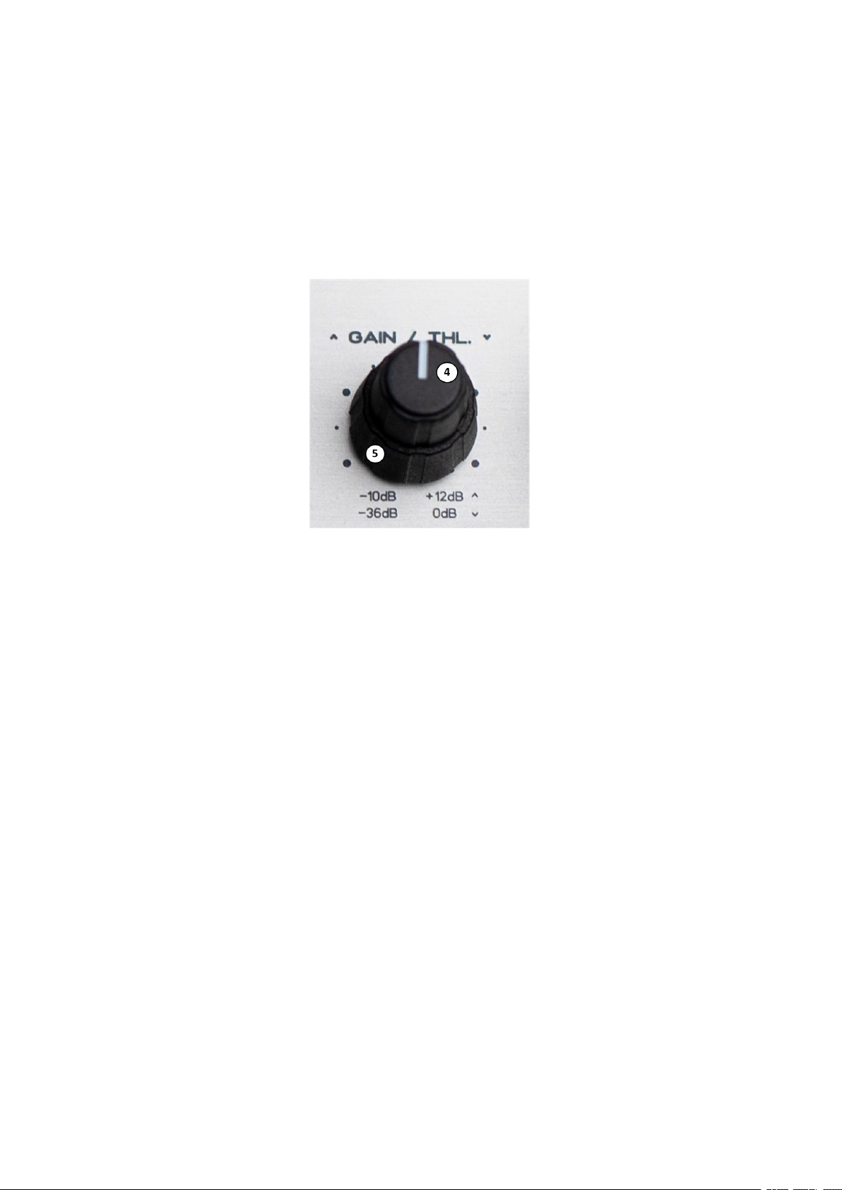
5.1 Input Gain & Threshold Controls
Figure 3: Input Gain & Threshold Controls
Input Gain (4) and Threshold (5) controls have been placed on the same poten-
tiometer, helping the user to define the desired point at which the compressor
start working. The upper knob sets the Input Gain for the corresponding chan-
nel; it ranges from -10 dB to +12 dB relative to the input level, with the blue dot
on the scale corresponding to unity gain. The lower knob sets the Threshold for
the corresponding channel; it ranges from -36 dB to 0 dB relative to the intenal
maximum threshold level.
7
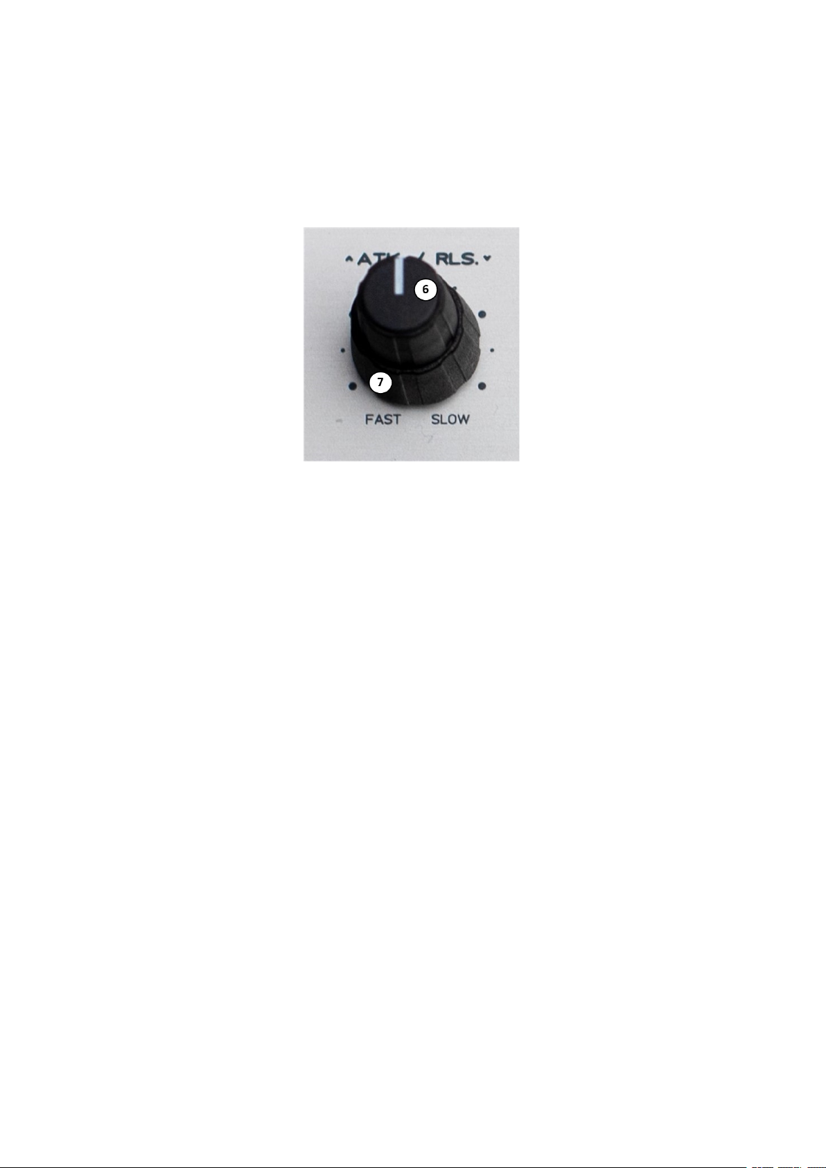
5.2 Attack & Release Controls
Figure 4: Attack & Release Controls
The Attack (6) and Release (7) controls have been placed on the same poten-
tiometer, helping the user to define the desired times at which the compression
start and stop working. The upper knob sets the Attack for the corresponding
channel; it ranges from fast (0.05 ms for a 10 dB attenuation) to slow (50 ms for
a 10 dB attenuation). The lower knob sets the Release for the corresponding
channel; it ranges from fast (5 ms for a 10 dB attenuation) to slow (500 ms for a
10 dB attenuation).
8

5.3 Ratio & Knee Control
Figure 5: Ratio & Knee Control
The Ratio control (8) sets the amount of compression that is applied to the signal
of the corresponding channel; it ranges from 1:1 (i.e. no compression) to Limit
(i.e. limiter). The Knee (9) switch sets the slope of the compression applied to the
signal; it can be used to set a soft-knee slope (left position) or a hard-knee slope
(right position).
9

5.4 Make Up & Mix Control
Figure 6: Make Up & Mix Control
The Mix (11) control sets the amount of compressed and uncompressed signal
that is sent to the Make Up stage. This control allows the user to implement
parallel compressions; it ranges from 0% (i.e. only uncompressed signal) to 100%
(i.e. only compressed signal). The Make Up (10) control sets the amount of gain
that is applied to the signal coming from the Mix stage; it ranges from -10 dB to
+20 dB.
10
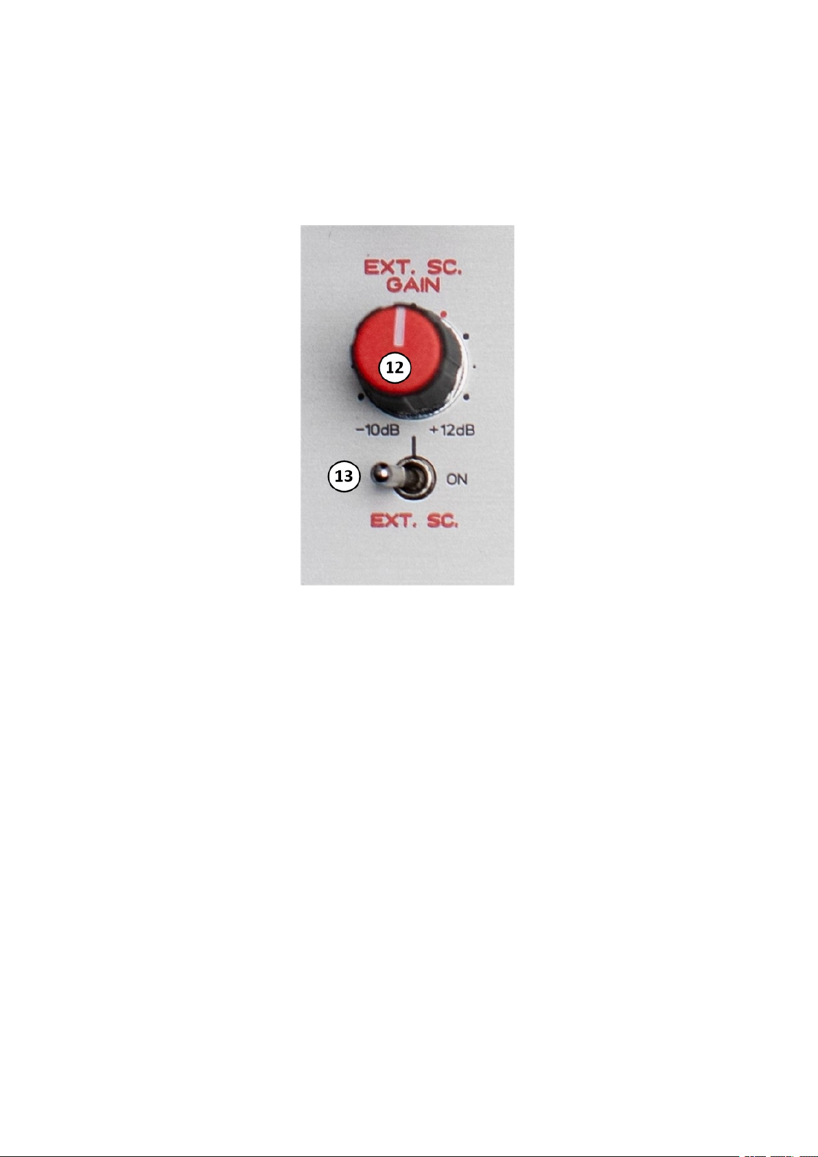
5.5 External Side-chain Gain
Figure 7: External Side-chain Gain
The External Side-chain Gain (12) sets the gain applied to the signal connected in
the External Side-chain Jack for the corresponding channel; it ranges from -10
dB to +12 dB relative to input level, with the red dot on the panel corresponding
to unity gain. When the External Side-Chain (13) switch is ON, the external signal
is used to drive the compression, that is, it is used as side-chain.
11
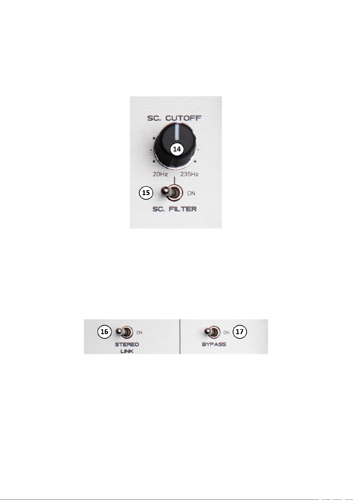
5.6 Side-chain Cut-off Control
Figure 8: Side-chain Cut-off Control
The Side-chain Cut-off (14) control sets the cutoff frequency of a 1st order hi-pass
that filters the side-chain signal; it ranges from 20 Hz to 235 Hz. When the Side-
Chain Filter (15) switch is ON, the hi-pass filtering is applied to the side-chain
signal.
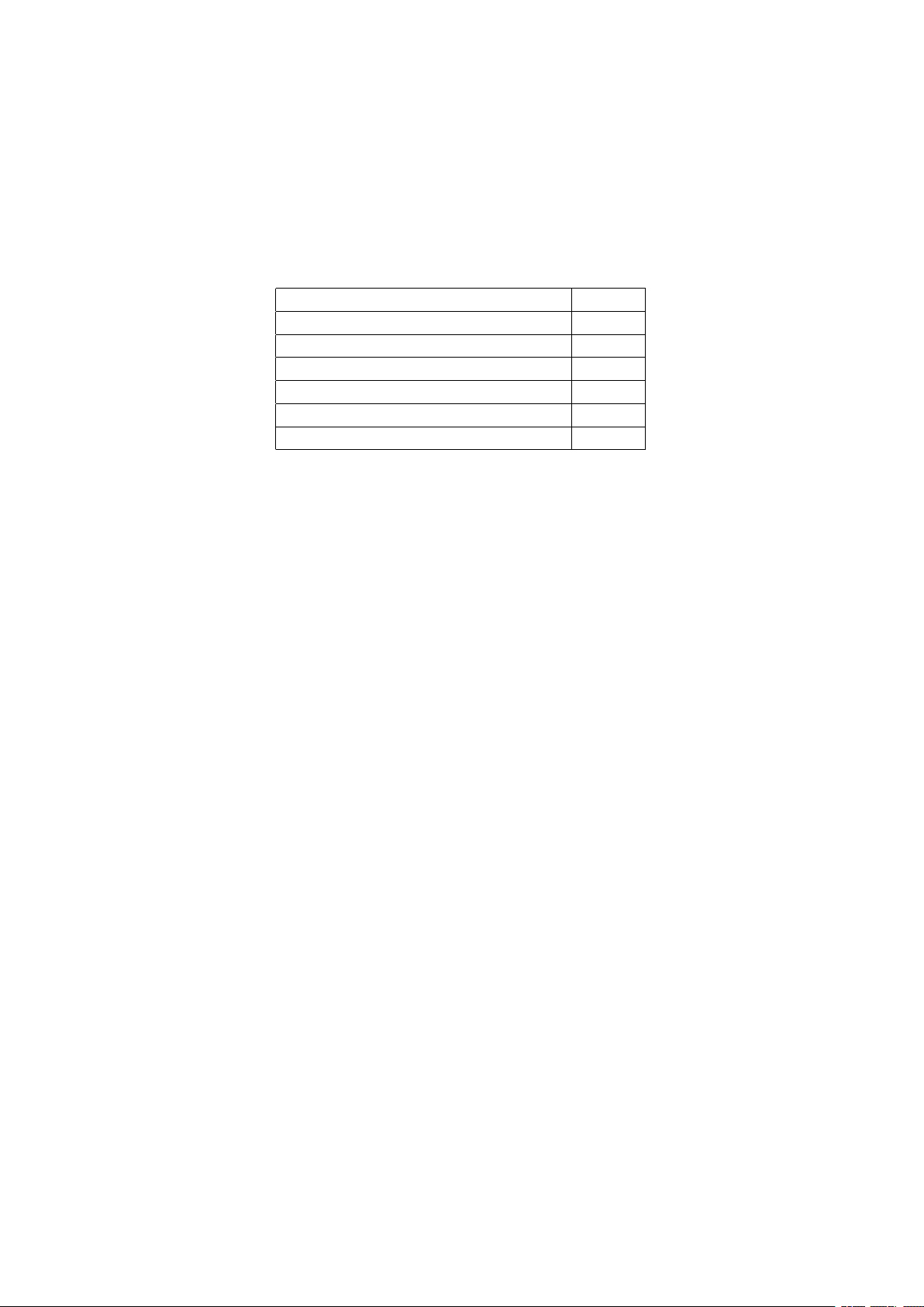
5.7 Bypass & Stereo Link Control
Figure 9: Bypass & Stereo Link Control
The Stereo Link (16) switch can be used to link the mono compressors side-chains.
When the switch is active (i.e. ON position), the side-chain signals are summed
and rescaled in order to have both compressors driven by the same side-chain
signal. The Bypass (17) switch, when is active (i.e. ON position), can be used
to monitor the uncompressed signal. The uncompressed signal is acquired after
the Input Gain stage.
12

6 Attenuation Led Bars
Figure 10: Attenuation Led Bar
DYNAMICENGINE features two vertical Led Bars that monitor the amount of com-
pression applied to the signals. When the Bypass switch is activated (that is, when
the user is monitoring the uncompressed signal) the led bars are bypassed. The
Led Bars show attenuation from -20 dB to 0 dB.
13

7 Power Connection
Figure 11: Power Connection
DYNAMICENGINE uses a standard Eurorack 10 pin connector. Since the con-
nector is not keyed users must pay attention to the connection orentation, even
if we implemented a reversed power connection protection. Connect the female
connector with the red wire of the power cable as indicated on the PCB.
14
8 Specifications
In the following table are provided mechanical and electrical specifications.
Parameter Value
Width 28 HP
Height 3U
Recommended PSU Positive Voltage +12 V
Recommended PSU Negative Voltage -12 V
+12 V consumption 160 mA
-12 V consumption 160 mA
Table 1: Specifications
15
Table of contents
Other Audio Gear Obsession Dj Equipment manuals


