TMB Solaris Flare Q+ RZ 50 User manual

Flare Q+ RZ
Operation Manual
TMB 24/7 Technical Support
US/Canada: +1 818.794.1286
Toll Free: 1 877.862.3833 (877.TMB.DUDE)
UK: +44 (0)20.8574.9739
Toll Free: 0800.652.5418
e-mail: techsupport@tmb.com
2
Overview
Solaris Flare indoor LED fixtures are combination wash/strobe/blinders with class-leading LED RGBW
brightness with greater than 9,500 lumens (Rayzr 50 cm) and greater than 19,500 lumens (Rayzr 100 cm).
Features include instant color mixing and 1200Hz refresh rate for smooth on-camera dimming. Q+ technology
increases the brightness with virtually no additional fan noise.
Note: Solaris Flare Rayzr Q+ 50 cm has two cooling fans and one safety hitch.
3
Specifications
Solaris Flare Q+ Rayzr
50 cm
100 cm
Light sources
18 CREE© LEDs
(divided in to 6 pixels)
36 CREE© LEDs
(divided in to 12 pixels)
Beam Spread
36°, optional beam angles available: 20°, 54°, and 70°
Colors
R, G, B, W
Average color wavelength
(manufacturer rated) Red: 625 nm, Green: 530 nm, Blue: 460 nm, White: >5700K
Refresh rate
1200 Hz
Intensity control
16-bit or 8-bit
Operating Voltage
100-240VAC 50/60Hz
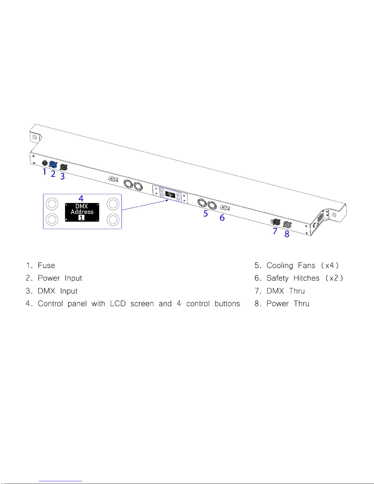
Fuse
2A 250V slow-blow (5x20mm)
4A 250V slow-blow (5x20mm)
Cooling
Air cooling + fan
Operating temperature
-4 °F - +104 °F (-20 °C - +40 °C)
DMX channels
3-32 depending on control mode
3-56 depending on control mode
DMX connectors
Input 5-pin XLR male, Thru 5-pin XLR female
DMX pin configuration
pin 1 shield, pin 2 (data-), pin 3 (data+), pin 4 n/a, pin 5 n/a
Max. power draw
200 W
400 W
RDM support
Yes
Power Connector Input
PowerCON 20A blue
Fixing
Adjustable yoke
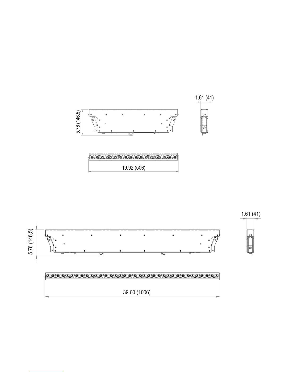
Unit Dimensions (LxWxH)
19.92 x 1.61 x 5.76 in
(506 x 41 x 146,5 mm)
39.60 x 1.61 x 5.76 in
(1006 x 41 x 146,5 mm)
Shipping Dimensions (LxWxH)
22.25 x 7.67 x 10.62 in
(565 X 195 X 270 mm)
41.92 x 7.67 x 10.62 in
(1065 X 195 X 270 mm)
Unit Weight
8.16 lb. (3,7 kg)
13.89 lb. (6,3 kg)
Shipping weight
10.58 lb. (4,8 kg)
15.65 lb. (7,1 kg)
4
Unpacking Instructions
Upon receipt of the fixture, carefully unpack the carton and check the contents to ensure that all parts are
present and in good condition. Notify the shipper immediately and retain packing material for inspection if any
parts appear to be damaged from shipping or if the carton itself shows signs of mishandling. Save the carton
and all packing materials. If a fixture must be returned to the factory, it is important that the fixture be returned
in the original factory box and packing.
Power Requirements
Before powering the unit, make sure the line voltage is within the range of accepted voltages. Fixtures
operating voltage is 100-240 VAC 50/60Hz. All fixtures must be powered directly from a switched circuit and
cannot be operated with a rheostat (variable resistor) or dimmer circuit, even if the rheostat or dimmer channel
is used solely as a 0-100% switch.
When powered up, Solaris performs a preprogrammed internal test. On initial power-up the factory default
DMX address appears on the display screen and Solaris is ready for operation. After initial power-up, the last-
saved DMX address will appear.
Frequency Settings
Depending on location, change the Default Frequency setting to match the mains power (e.g., US and Canada
should be set at 60Hz). Proper frequency setting will ensure minimum number of visible artifacts when using
Solaris on camera.
Safety Instructions
•
Please keep this Operation Manual for future reference. If the unit is sold to another user, make sure they
also receive this instruction booklet.
•
Ensure fixture is connected to proper voltage, and that line voltage is not higher than that stated on the
fixture.
•
Make sure there are no flammable materials close to the unit while operating.
•
Always disconnect from the power source before servicing or fuse replacement. Always use thefuse
specified in this manual.
•
Always use a safety cable when hanging fixture overhead.
•
Maximum ambient temperature (Ta) is 40°C (104°F). Do not operate fixture at temperatures above this
rating.
•
In the event of a serious operating problem, stop using the unit immediately. Repairs must be carried out
by trained, authorized personnel. Contact the nearest authorized technical assistance center. Only OEM
spare parts should be used.
•
Do not connect the device to a dimmer pack.
•
Make sure power cord is never crimped or damaged.
•
Never disconnect power cord by pulling or tugging on the cord.
•
Avoid direct eye exposure to the light source during operation.
Caution! There are no user serviceable parts inside the unit. Do not open the housing or attempt any
repairs yourself. In the unlikely event your unit may require service, please contact your distributor.
Please read these instructions carefully. This user guide
contains essential information about the installation, usage and
maintenance of this fixture.
5
Dimensions
Solaris Flare Q+ Rayzr 50 cm
Dimensions in inches (mm)
Solaris Flare Q+ Rayzr 100 cm
Dimensions in inches (mm)
6
Setup
Fuse Replacement
1. Flare Q+ Rayzr devices use a slow-blow fuse (5x20mm).
•Flare Q+ Rayzr 50 uses a 2A 250V fuse
•Flare Q+ Rayzr 100 uses a 4A 250V fuse
To replace a Fuse:
2. With a screwdriver turn the fuse cap counter-clockwise to remove fuse cap with fuse.
3. Replace fuse attached to fuse cap.
4. Reinsert fuse cap with new fuse and tighten clockwise.
Power Linking
Solaris Flare Q+ Rayzr has Neutrik® PowerCon IN and THRU connections allowing power linking (daisy-chaining).
Depending on the power provided, you should not exceed the power threshold.
Max. 5 units 100-120V; max. 10 units 208-240V for Flare Q+ Rayzr 50cm.
Max. 3 units 100-120V; max. 6 units 208-240V for Flare Q+ Rayzr 100cm.
Fixture Linking
A DMX data link is needed to operate one or more fixtures via a DMX-512 lighting console. The combined number
of channels required by all the fixtures on a DMX data link determines the number of fixtures the DMX data link
can support.
Important: Fixtures on a DMX data link must be daisy-chained in one single line. To comply with the EIA-
485 standard, no more than 32 devices should be connected on one data link. Connecting more than 32
fixtures on one serial data link without the use of a DMX optically-isolated splitter may result in
deterioration of the digital DMX signal.
Maximum recommended DMX data link distance between fixtures: 984 ft. (300 meters).
Disconnect the power cord before replacing the
fuse. Always replace with the correct fuse type.
7
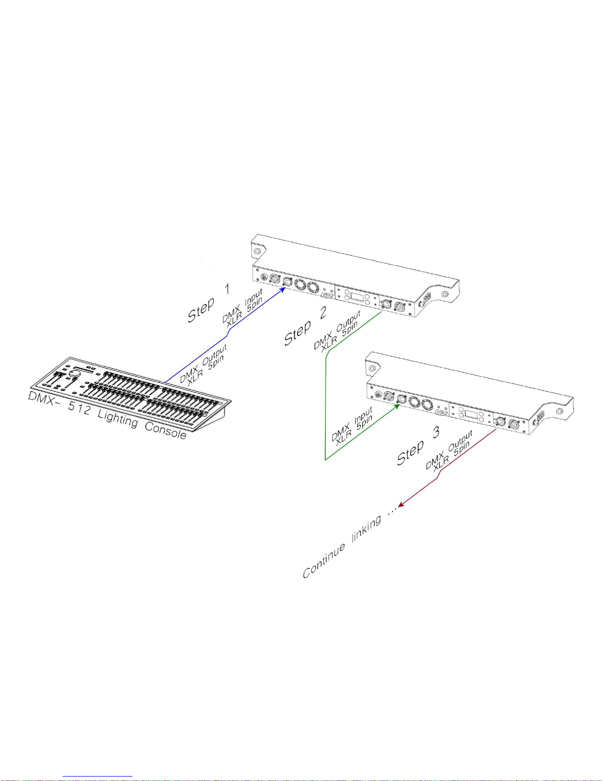
Setting up a DMX Serial Data Link
1)
Connect the male 5-pin XLR connector of the data cable to the female 5-pin XLR output of the DMX console.
Connect the other end of the data cable (female 5-pin XLR) to the male 5-pin XLR connector located on the
Solaris Flare.
2)
Connect from the fixture output as stated above to the input of the following fixture.
3)
Continue linking until the last fixture is connected in your DMX signal data chain.
8
Fixture Mounting
Orientation
Flare Q+ Rayzr fixtures may be mounted in any position. Each have a yoke with mounting hole for clamps or
couplers. Always make sure there is adequate room for ventilation. Do not obstruct the unit’s fan or vents.
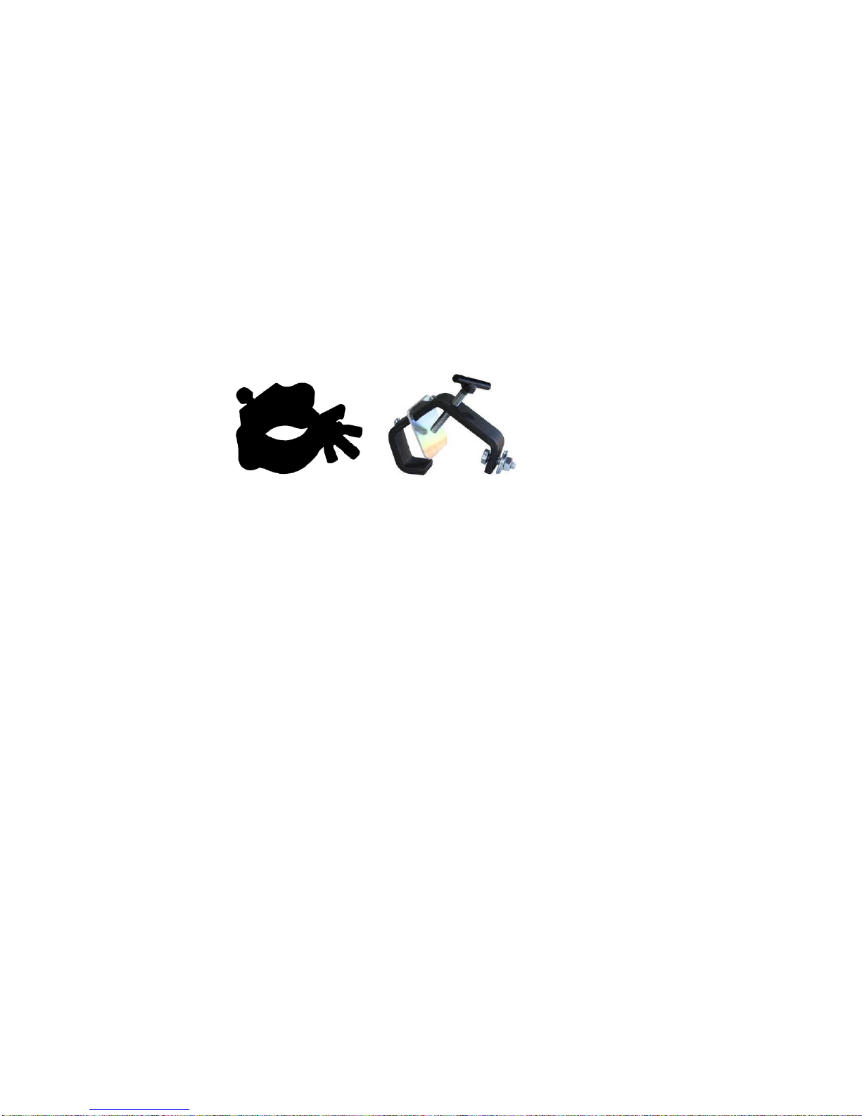
Rigging
To avoid possibility of risk, both Rayzr fixtures comes with a hitch to be used with safety cables. Always
consult a certified rigging specialist before suspending any fixture overhead!
Use ProBurger® couplers or equivalent C- or O-type clamps for attaching to truss. It is important never to obstruct
the fan or vents pathway. Adjust the angle of the fixture by loosening both knobs and tilting the fixture. After finding
the desired position, retighten both knobs.
Note!
•Always use safety cables!
•When selecting installation location, consider routine maintenance.
•Never mount fixture where it will be exposed to moisture, excessivehumidity, extreme temperatures, or
restricted ventilation.

9
Fixture accessories
Dimensions in inch (mm)
Rayzr Joining Adapter
•Unit Weight: 0.44 lb. (0,2 kg)
•Maximum vertical length for joined Rayzrs is 5 meters
10
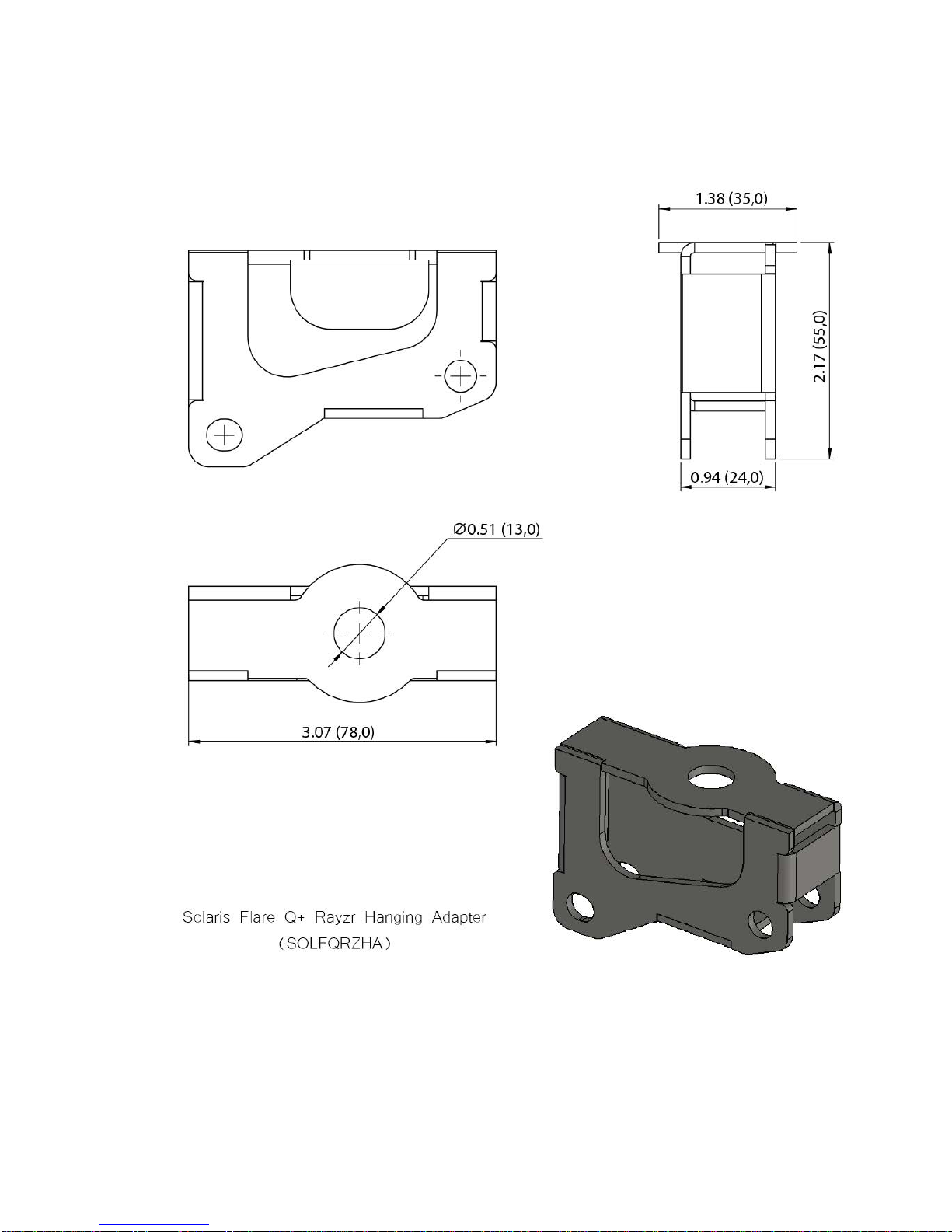
Rayzr Hanging Adapter
•Unit Weight: 0.57 lb. (0,26 kg)
11
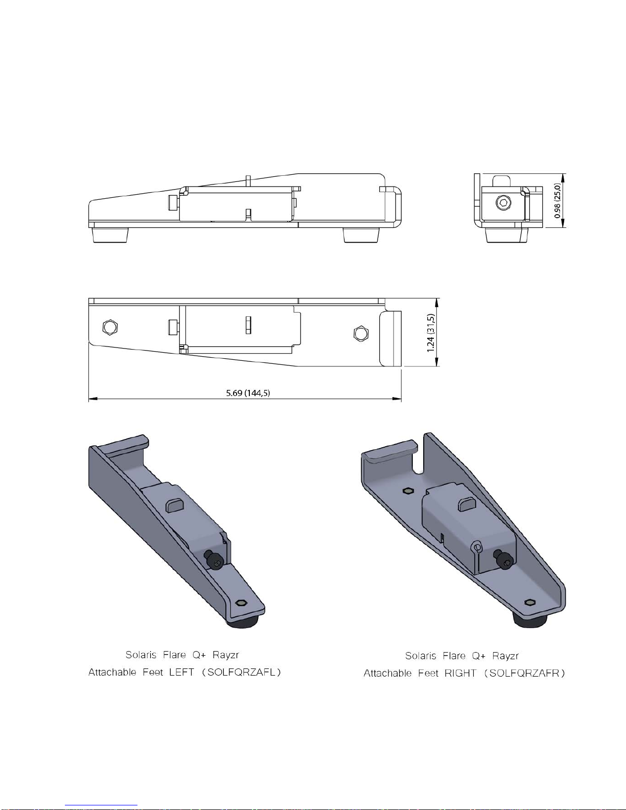
Rayzr Attachable Feet
•Unit Weight: 0.88 lb. (0,4 kg) per set

12
Rayzr Scenery Mount
•Unit Weight: 0.11 lb. (0,05 kg)

13
Rayzr Locking Clip
•Unit Weight: 0.02 lb. (0,01 kg)
Rayzr Locking Pin
•Unit Weight: 0.08 lb. (0,04 kg)
14
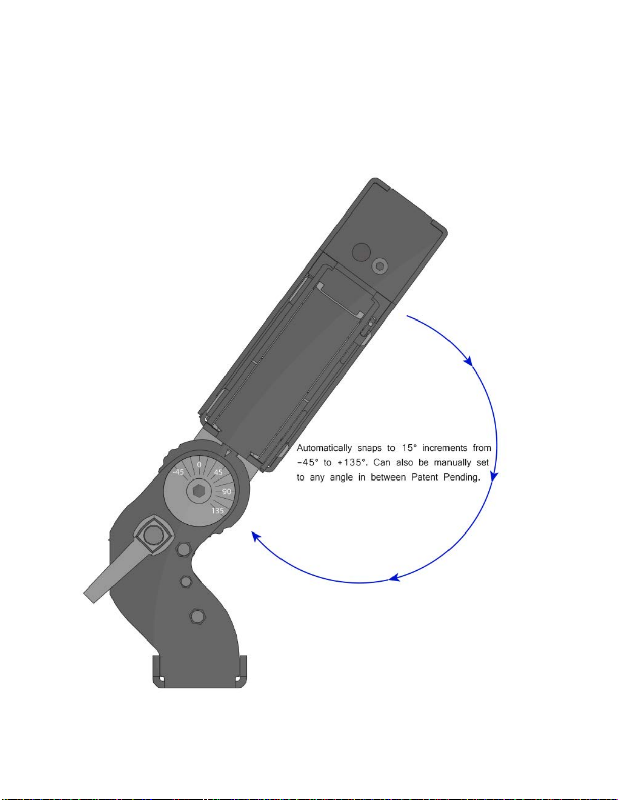
PreSet Yoke™included with fixture
15
Operating Instructions
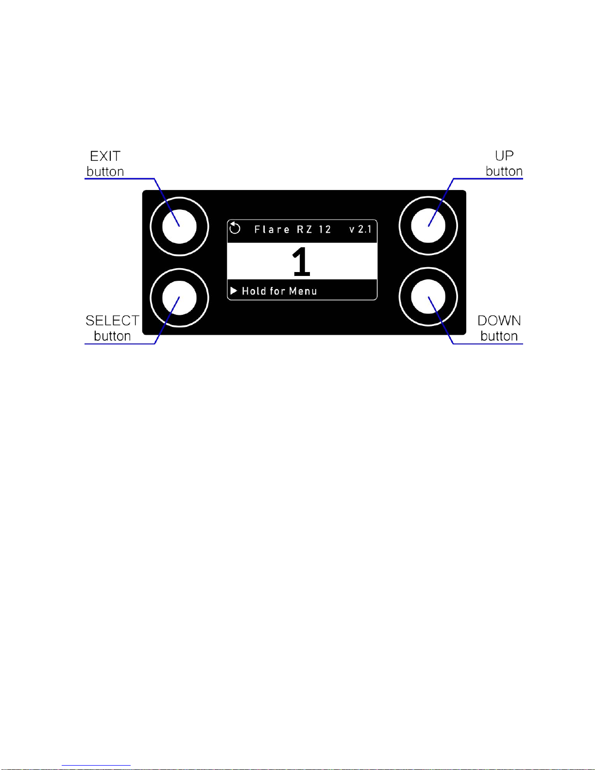
Control Panel Navigation
Access control panel functions using the four control panel buttons.
The Control Panel LCD Display shows the menu items selected from the menu map (see pages 16- 17). When
a menu function is selected, the display will show the first available option for the selected menu function. To
select a menu item, press <SELECT>.
Press and hold the <SELECT> button to scroll through the top-level menu items. This is the top of the menu
map. Use the <UP> and <DOWN> buttons, located to the right of the LCD screen, to navigate the menu map
and menu options. Press the <SELECT> button to access the menu function currently displayed or to enable
a menu option. To return to the top of the menu map or main screen without changing the value, press the
<EXIT> button.
Main Menu Functions
DMX Address – DMX address selection
Control – Control mode selection menu
Manual – Manual Control Demo – Demonstration scenes Config – Configuration Menu
During normal operation, the Control Panel LED Display indicates DMX start address. When the DMX signal is
not connected, or if the Flare is not receiving a DMX signal, the address blinks.
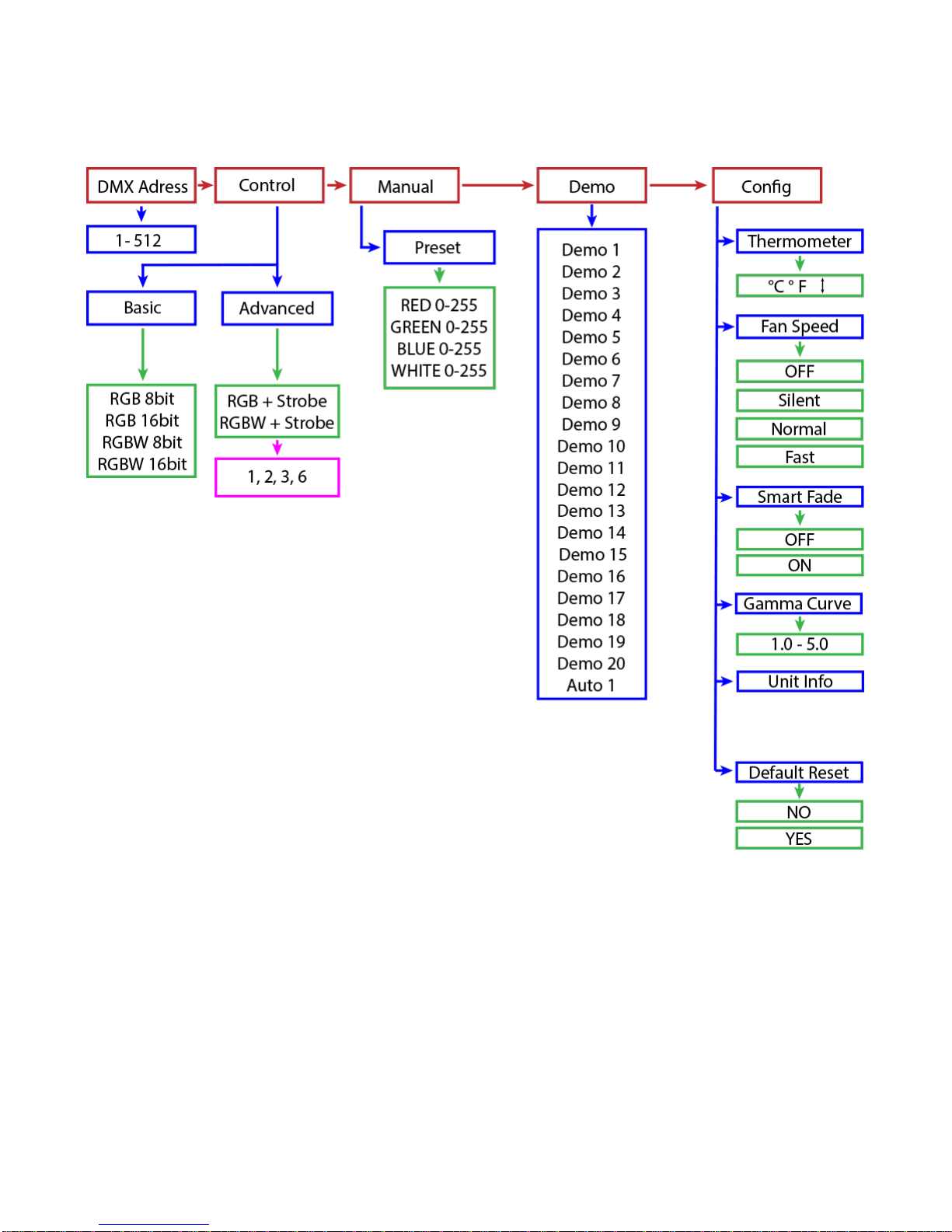
16
Menu Map – Rayzr Q+ 50 cm

17
Menu Map – Rayzr Q+ 100 cm

18
Menu Function Description
DMX Address – To set the required DMX address, open the Main Menu:
1)
Press and hold <SELECT> button to open the Main Menu.
2)
Use <UP> and <DOWN> buttons to find the DMX address function.
3)
Press <SELECT> button to access the DMX address value change submenu.
4)
Use <UP> and <DOWN> buttons to set necessary DMX address value.
5)
Use <SELECT> button to confirm the new DMX address.
6)
Main Menu will appear. Press <EXIT> button to return fixture at work-state.

19
7)
The work-state control panel display shows current DMX address (e.g. 16).
– Flare fixtures are two fixtures in one (strobe and a wash/blinder). In each of the control modes, the fixture
occupies varying numbers of DMX channels and has different control channels. To enter the Control submenu,
follow these steps:
1)
Press and hold <SELECT> button to open the Main
Menu.
2)
Use <UP> and <DOWN> buttons to find the Control
submenu.
3)
Press <SELECT> button to access the Control
submenu.
4)
Choose the correct Control Mode type.
Basic – This mode allows for simple control of the fixture
as a Blinder/Wash fixture or as a Strobe.
Advanced – This mode allows for independent control of
Blinder/Wash functions and the Strobe functions. This
mode also allows for independent color and intensity
control of every segment of LEDs independently.
20
Basic Mode
In Basic Mode, the fixture can be used as a wash/blinder, generic strobe, or color strobe. The first modes are
the RGB and RGBW modes in 8- bit resolution or 16-bit resolution.
The RGB modes are designed to automatically adjust the white LEDs according to the RGB mix coming from
the lighting controller.
The RGBW modes are designed to give independent control of all 4 colors.
8-bit control uses one DMX channel for each color, and 16-bit control allows for two DMX channels of control to
give the lighting controller more steps of dimming.
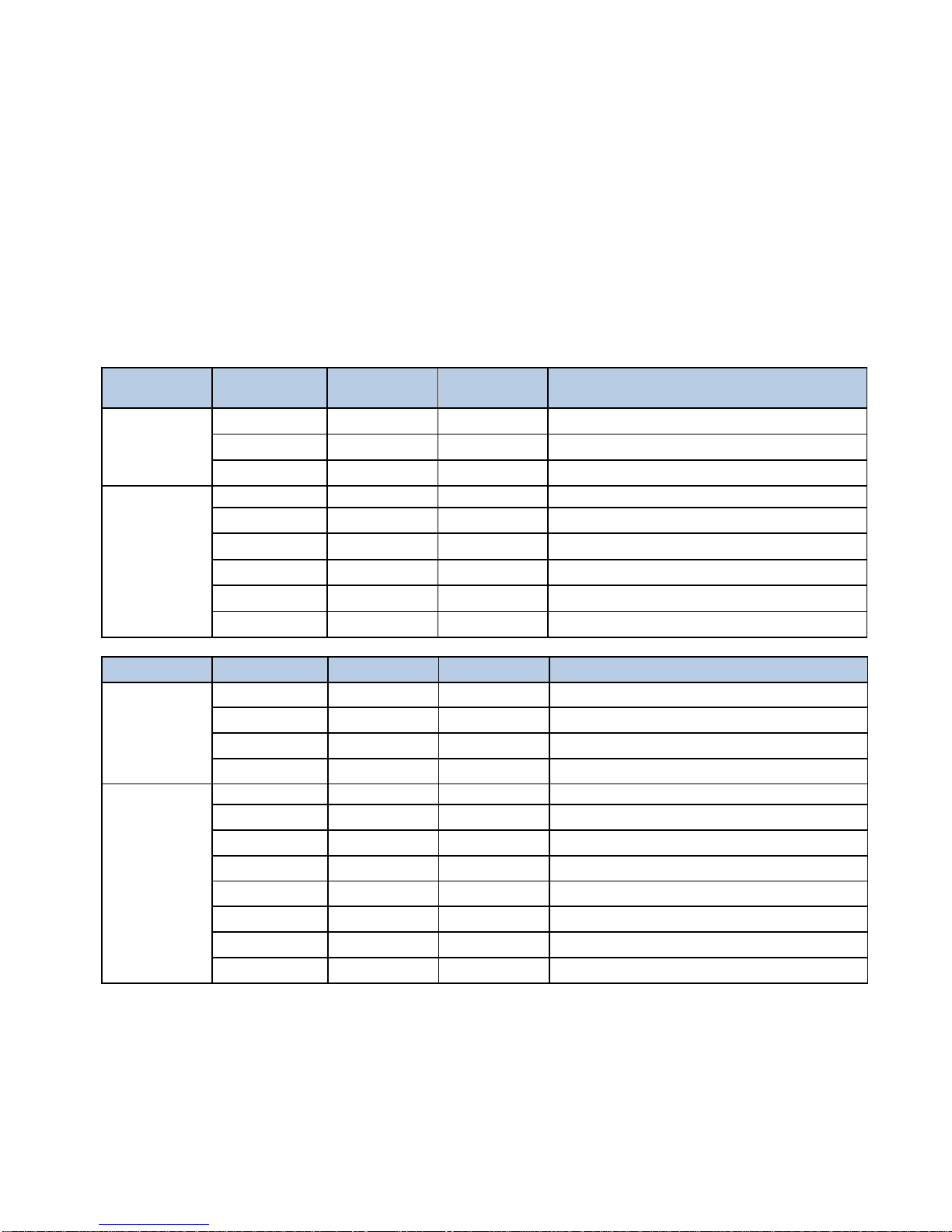
Mode Channel DMX
values
Preset Function
RGB
8bit
1
0 - 255 0 - 100 Red Intensity
2
0 - 255 0 - 100 Green Intensity
3
0 - 255 0 - 100 Blue Intensity
RGB
16bit
1
0 - 255
0 - 100
Red Intensity HI Byte
2
0 - 255 0 - 100 Red Intensity LOW Byte
3
0 - 255 0 - 100 Green Intensity HI Byte
4
0 - 255 0 - 100
Green Intensity LOW Byte
5
0 - 255 0 - 100 Blue Intensity HI Byte
6
0 - 255 0 - 100 Blue Intensity LOW Byte
Mode
Channel
DMX values
Preset
Function
RGBW
8bit
1
0 - 255 0 - 100
Red Intensity
2
0 - 255 0 - 100 Green Intensity
3
0 - 255 0 - 100
Blue Intensity
4
0 - 255 0 - 100
White Intensity
RGBW
16bit
1
0 - 255
0 - 100
Red Intensity HI Byte
2
0 - 255 0 - 100 Red Intensity LOW Byte
3
0 - 255 0 - 100
Green Intensity HI Byte
4
0 - 255 0 - 100 Green Intensity LOW Byte
5
0 - 255 0 - 100
Blue Intensity HI Byte
6
0 - 255 0 - 100 Blue Intensity LOW Byte
7
0 - 255 0 - 100
White Intensity HI Byte
8
0 - 255 0 - 100
White Intensity LOW Byte
This manual suits for next models
3
Table of contents
Other TMB Dj Equipment manuals


