Audio international AV-4590-0x-x User manual

7300 Industry Drive, North Little Rock, AR 72117
Phone: 501-955-2929 Fax: 501-955-2988
Installation & Operations
Manual
Model #: AV-4590-0x-x
Audio/Video Distribution Unit
Document #540108

Audio International, Inc. AV-4590-0x-x Installation & Operation
Document #540108, Rev. IR, 11/1999 Page 2 of 18
Document Revision History
Rev. Level Date Description
IR 11/1999 Initial Release
Reference Documents
Document # Drawing # Description
N/A 522237 AV-4590-0x-x Outline Drawing
Service Bulletin List
Service
Bulletin # Subject Manual
Revision Revision
Date
Table of Illustrations
Illustration # Description Page #
1 Block Diagram – Typical application 6
2 Reference Drawings 19
PROPRIETARY INFORMATION NOTICE: Despite any other copyright notice, this document and
information disclosed herein contains confidential, proprietary designs owned by Audio
International, Inc. Neither this document nor the data contained herein shall be reproduced, used
or disclosed to anyone without the written authorization of Audio International, Inc.

Audio International, Inc. AV-4590-0x-x Installation & Operation
Document #540108, Rev. IR, 11/1999 Page 3 of 18
Table of Contents
Section Description Page
1.0 General Information ……………………………………………. 4
1.1 Introduction ……………………………………………………….. 4
1.2 Purpose of the Equipment ………………………………………. 4
1.3 Operational Features …………………………………………….. 4
1.4 Optional Equipment ……………………………………………… 5
2.0 Application ……………………………………………………….. 5
2.1 Introduction ……………………………………………………….. 5
2.2 Typical Application………………………………………………... 5
2.3 Block Diagram –Typical Application …………………………… 6
2.4 Multiple Unit Configurations……………………………………… 6
2.5 Data Bus Control………………………………………………….. 6
3.0 Installation ……………………………………………………….. 7
3.1 Prior to Installation ……………………………………………….. 7
3.2 Unpacking and Inspection ………………………………………. 7
3.3 Cautions & Warnings …………………………………………….. 8
3.4 Wiring Requirements …………………………………………….. 8
3.5 Physical Characteristics………………………………………….. 9
3.6 Electrical Characteristics…………………………………………. 10
3.7 Mating Connector Information ……………. ……………………. 11
3.8 Pinout Assignment Descriptions ………………………………... 12
3.9 Post-Installation Test …………………………………………….. 15
4.0 Operation ………………………………………………………… 15
5.0 Troubleshooting ………………………………………………… 15
5.1 General Troubleshooting Procedures ………………………….. 15
5.2 Troubleshooting Chart …………………………………………… 16
6.0 Specifications …………………………………………………… 17
6.1 Unit Specifications ……………………………………………….. 17
7.0 Reference Drawings ……………………………………………. 18

Audio International, Inc. AV-4590-0x-x Installation & Operation
Document #540108, Rev. IR, 11/1999 Page 4 of 18
MODEL # AV-4590-0x-x
Audio/Video Distribution Unit
1.0 General Information
1.1 Introduction
This manual contains information for the proper application, installation
and operation of the Audio International, Inc. (AI) Audio Video Distribution
Unit, Model No: AV-4590-0x-x. The “-0x”suffix designates the
configuration of the unit. The “-x”in the model number designates the
type of connector utilized in installation. Also included are physical and
electrical characteristics of the unit.
1.2 Purpose of the Equipment
The AV-4590-0x-x is an audio/video distribution unit that has been
specifically designed to meet the special requirements of aircraft use. It is
used to provide audio and video selections for the cabin entertainment
system.
1.3 Operational Features
The AV-4590-0x-x allows up to eight (8) entertainment audio inputs plus
thirteen (13) independent Audio-on-Demand inputs, and twenty-four (24)
audio outputs. Dual ten-band graphic equalizers and audio mute input are
provided along with two ID inputs to allow up to four units to be installed
on the same data bus. The unit is configurable via the data bus to
individually set power up defaults for audio selection, volume, bass and
treble, and equalizer control.
Twelve input arrangements for video sources can be connected to each
Audio Video Distribution Unit. Video sources may include units such as
the VCP, DVD, Video Briefer, or other video devices. The unit is equipped
with sixteen video outputs. These video outputs allow the unit to display
multiple video inputs on separate monitors independently.
This distribution unit is equipped with a video briefer key input and the
video briefer source may be configurable via AI’s proprietary RS-485 data
bus. Power up default video selection is configurable for each output.
(Video briefer and PA input are independent of each other.)

Audio International, Inc. AV-4590-0x-x Installation & Operation
Document #540108, Rev. IR, 11/1999 Page 5 of 18
1.4 Optional Equipment
The following entertainment units are typical of those which can be
installed in the aircraft and utilized with the AV-4590-0x-x: Video Cassette
Player, CD Player, Cassette Tape Player, Audio Amplifier, Digital
Equalizer, Page/Chime Unit, Touch Screen LCD Monitor, and Digital
Video Disc Player. Additional distribution units may be installed to meet
audio and video requirements of the aircraft configuration. All settings are
retained in non-volatile memory.
Upon request, Audio International will provide PC software to control
internal settings in the AV-4590-0x-x (i.e. audio levels, chime/page, and
audio configuration). The software has been designed to be used with AI
module, MSM2912, CMS data bus interface.
Contact your AI representative for details.
2.0 Application
2.1 Introduction
The AV-4590-0x-x is part of a complete cabin audio entertainment system.
The application of the unit is specific to a particular aircraft based on the
desires of the customer and designer.
2.2 Typical Application
The AV-4590-0x-x provides a switching matrix for complex cabin
entertainment systems utilizing multiple source audio/video inputs and
outputs. Since the module resides on AI’s proprietary RS-485 data bus,
any switch or control device on the bus can independently select from
amongst the input sources. If the aircraft is equipped with Audio-on-
Demand, selecting this source switches to the AOD server, giving the
ability to select from any of thirteen (13) AOD channels.
Audio outputs are typically headphone stations located at seats or other
positions. Two outputs are interfaced with an internal graphic equalizer.
These two are connected to an external power amplifier to drive cabin
speakers.
Video outputs are typically passenger LCD screens or cabin monitors.
Input for a PA/Chime box allows PA audio to be distributed to all audio
stations and to the cabin speakers. PA and Video Briefer key inputs
override the entertainment systems.

Audio International, Inc. AV-4590-0x-x Installation & Operation
Document #540108, Rev. IR, 11/1999 Page 6 of 18
2.3 Block Diagram
2.4 Multiple Unit Configurations
If more than 24 audio or 16 video output stations are needed, multiple-unit
configurations are possible on AI’s RS-485 data bus. This allows
independent selection of any audio/video sources from any station. Up to
four (4) AV-4590-0x-x Audio/Video Distribution Units may be used on the
same data bus yielding a large number of potential inputs and outputs.
2.5 Data Bus Control
There are no accessible controls on the AV-4590-0x-x. Switching control
of the unit and selection of the graphic equalizer modes is handled by
commands via the AI’s RS-485 serial data bus.
Most programmable features are set upon installation using an external
PC (typically a laptop). A software program designed by AI specifically for
this task sets the following configurations:
q
power-up state for each audio and video station
q
video briefer source unit
q
trim levels for each audio input source
q
digital graphic equalizer settings
Audio
Amplifier
Passenger
LCD’s
Passenger
Headphones
Cabin
Monitors
AIRSHOW
DVD
VCP
CD
PA
AV-4590-0x-x
AudioIn
VideoIn
AudioOutVideoOut

Audio International, Inc. AV-4590-0x-x Installation & Operation
Document #540108, Rev. IR, 11/1999 Page 7 of 18
3.0 Installation
3.1 Prior to Installation
3.1.1 During the design and layout of the aircraft cabin, careful
consideration of the location of this and all other audio/video
modules is necessary. Some items to be considered include:
• space
• proximity to other audio and video equipment
• available power supply
• length of cable runs
• environmental conditions (humidity, temperature, etc.)
3.1.2 The AV-4590-0x-x installation must conform to standards
designated by the customer, installing agency, and existing
conditions as to location and type of installation.
3.1.3 Select a mounting location for the distribution unit. Refer to
Section 7.0 for dimensions and attachment points.
3.1.4 Mounting screws are required to secure the unit. Refer to
Section 7.0, Reference Drawings, for mounting hole
diameters and configuration.
3.2 Unpacking & Inspection
Carefully open the packaging and remove the unit. Verify that all
components have been included in the package per the packing list.
Inspect the unit for damage. Retain the packing materials and packing
list.
If damage has occurred during shipping, a claim must be filed with AI
within 24 hours and a “Return Request Authorization Number”must be
obtained from AI. Refer to the front cover of this manual for address and
telephone number of Audio International. Repackage the unit in its
original packaging materials and return it to AI following instructions given
by the AI representative. If no return is necessary, retain the packing
materials for storage or reshipment if necessary.

Audio International, Inc. AV-4590-0x-x Installation & Operation
Document #540108, Rev. IR, 11/1999 Page 8 of 18
3.3 Cautions and Warnings
3.3.1 All audio output lines from the AV-4590-0x-x should be shielded
and properly grounded. Audio input lines should be shielded and
grounded at the source, unless indicated otherwise. Avoid placing
cables too near to high power wires.
3.3.2 It is important to do a pin-to-pin power and ground check on all
connectors. Ensure that power and ground are applied only where
specified. Damage to the unit may result if power or ground is
applied to the wrong points.
3.3.3 DO NOT connect or disconnect any speaker when power is applied
to the unit.
3.3.4 DO NOT remove any factory-installed screws. Damage to the units
may result and void any warranties.
3.3.5 DO NOT mount the unit to the skin of the aircraft.
3.3.6 The unit contains breakable components; DO NOT drop or subject
to heavy impact.
3.4 Wiring Requirements
3.4.1 Introduction
The installing agency must supply and fabricate all external cables
and mating connectors. The length and routing of external cables
must be carefully studied and planned before attempting installation
of the equipment. Allow adequate space for installation of cable
and connectors. Avoid sharp bends and placing cables near
aircraft control cables. Maintain a minimum clearance of three (3)
inches from any control cable. If wiring is run parallel to
combustible fluid or oxygen lines, maintain a separation of six (6)
inches between the lines.
3.4.2 Power Wires
All power and ground wires must be 20 AWG, minimum. Power
ground wires must be grounded within twelve (12) inches of the
unit. All wires must be in accordance with MIL-W-22759 or
equivalent. Twisted, shielded cable must be in accordance with
MIL-W-27500 or equivalent. Protect power wires with circuit
breakers or fuses located close to the electrical power source bus.

Audio International, Inc. AV-4590-0x-x Installation & Operation
Document #540108, Rev. IR, 11/1999 Page 9 of 18
3.4.3 Audio Lines
All audio input and output lines require 22 AWG minimum twisted
shielded pair. The cable shields must be grounded at the source.
3.4.4 Video Lines
All video input and output lines require coaxial cable, RG-179 or
equivalent.
3.4.5 RS-485 Data Bus
The AV-4590-0x-x is designed to interface with other AI equipment
via AI’s proprietary RS-485 serial data bus. This is a bi-directional
data bus that allows multiple units to be connected simultaneously.
The data bus is to be implemented using a twisted shielded pair
cable in accordance with MIL-W-27500 or equivalent. The wire
size for the conductors in this cable is to be 22 AWG (minimum).
The shield is to be connected wherever a shield pin is provided.
Shield terminations are to be made as close to the connector pin as
possible. In the event shield pins are not provided, the data bus
shield must be terminated per AI’s RS-485 specification.
All modules on the RS-485 data bus must be connected in a “daisy-
chain”configuration. AI’RS-485 serial data bus specification is
available upon request.
3.5 Physical Characteristics
3.5.1 The AV-4590-0x-x should be located away from heat sources,
magnetic fields, direct sunlight, and areas with excessive dust.
3.5.2 All adequate air circulation to prevent the build-up of internal heat.
3.5.3 Refer to Section 6.0 for unit dimensions.
3.5.4 Refer to Section 7.0 for attachment points.
3.5.5 When mounting the unit, allow sufficient space for mating
connectors.

Audio International, Inc. AV-4590-0x-x Installation & Operation
Document #540108, Rev. IR, 11/1999 Page 10 of 18
3.6 Electrical Characteristics
3.6.1 Refer to Section 6.0 for electrical specifications.
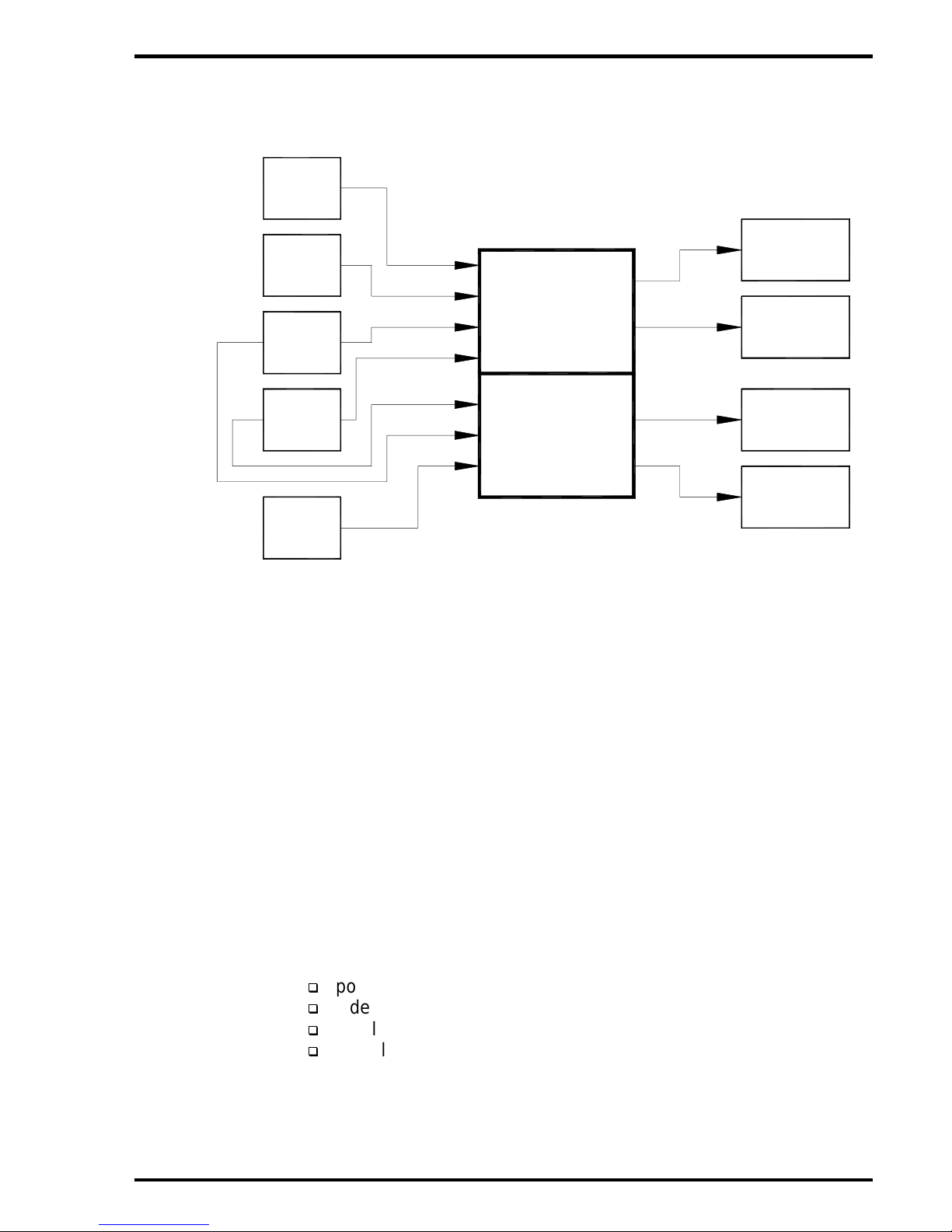
3.6.2 The AV-4590-0x-x utilizes eleven (11) connectors. The connectors
will be utilized per aircraft configuration requirements.
• P1, P2, and P3 are 8-pin connectors. The signals interfaced
through the pins are video output and video input. P1 provides
the input for up to eight (8) video sources, P2 provides video
input for an additional four (4) video sources and output for four
(4) video monitors. P3 provides output for eight (8) video
monitors. The inputs and outputs are 75-ohms, 1 V p-p (peak-
to-peak), composite video.
• P4 provides outputs for five (5) video monitors. The outputs are
75-ohms, 1 V p-p, composite video.
• P5 is a 50-pin connector that provides electrical connections for
left and right audio inputs. Eight (8) audio source inputs are
provided. The input levels are 1 to 5V RMS at 4.7 K-ohms (2V
RMS optimal).
• P6 is a 37-pin connector that provides outputs for 12 audio
stations. Eleven (11) outputs are rated at 500 mW at 50-ohms.
The output on pins 1 through 3 are processed by the on-board
graphic equalizer. These pins are suitable for connection to an
external amplifier. (If pins 1 through 3 are utilized, pins 13
through 15 on P10 should not be used.)
• P7 is a 15-pin connector that provides left and right headphone
audio outputs, RS-485 data bus control, and briefer key control.
Power input and power ground is +28 VDC. PA audio high and
low input level is approximately 1 –2 V p-p. Key input from the
PA system is ground active to override entertainment audio. (If
the aircraft is equipped with a video briefer, a key input from this
system will override entertainment video.) Pin 11 provides an
audio mute function. Unit ID inputs are provided on pins six (6)
and seven (7).
• P8 is a 37-pin connector that provides inputs for eight (8) Audio-
on-Demand channels. The input levels are 1 to 5V RMS at 4.7
K-ohms (2V RMS optimal).

Audio International, Inc. AV-4590-0x-x Installation & Operation
Document #540108, Rev. IR, 11/1999 Page 11 of 18
• P9 is a 25-pin connector that provides inputs for an additional
five (5) Audio-on-Demand channels. The input levels are 1 to
5V RMS at 4.7 K-ohms (2V RMS optimal).
• P10 is a 15-pin connector that provides outputs for five (5) audio
stations. Four (4) outputs are rated at 500 mW at 50-ohms.
Outputs on pins 13 through 15 are processed by the on-board
graphic equalizer. These pins are suitable for connection to an
external amplifier. (If pins 13 through 15 are utilized, pins 1
through 3 on P6 should not be used.)
• P11 is a 25-pin connector that provides outputs for an additional
eight (8) audio stations. Outputs are rate at 530 mW at 50-
ohms.
3.7 Mating Connector Information
All wiring harnesses to the unit are supplied and fabricated by the
installing agency.
Pin # Part # Description
P1 CB08WF000ZED Mating connector –Positronic
FCC4102D 8 each contacts –Positronic
P2 CB08WF000ZED Mating connector –Positronic
FCC4102D 4 each contacts –Positronic
MCC4102D 4 each contacts –Positronic
P3 CB08WF000ZED Mating connector –Positronic
MCC4102D 8 each contacts –Positronic
P4 CBD5WM000ZED Mating connector –Positronic
MCC4102D 5 each contacts –Positronic
P5 RD50F10JVL0 Mating connector –Positronic
P6 RD37M10JVL0 Mating connector –Positronic
P7 RD15F10JVL0 Mating connector –Positronic
P8 RD37F10JVL0 Mating connector –Positronic
P9 RD25F10JVL0 Mating connector –Positronic
P10 RD15M10JVL0 Mating connector –Positronic
P11 RD25M10JVL0 Mating connector –Positronic

Audio International, Inc. AV-4590-0x-x Installation & Operation
Document #540108, Rev. IR, 11/1999 Page 12 of 18
3.8 Pinout Assignment Descriptions
P1 P5
Pin # Description Pin # Description
A8 Video Input #1 1 Chassis Ground
A7 Video Input #2 2 Audio Input Left HI CH 1
A6 Video Input #3 3 Audio Input Right HI CH 1
A5 Video Input #4 4 Audio Input Left HI CH 2
A4 Video Input #5 5 Audio Input Right HI CH 2
A3 Video Input #6 6 Audio Input Left HI CH 3
A2 Video Input #7 7 Audio Input Right HI CH 3
A1 Video Input #8 8 Audio Input Left HI CH 4
9 Audio Input Right HI CH 4
P2 10 Audio Input Left HI CH 5
A8 Video Input #9 (F) 11 Audio Input Right HI CH 5
A7 Video Input #10 (F) 12 Audio Input Left HI CH 6
A6 Video Input #11 (F) 13 Audio Input Right HI CH 6
A5 Video Input #12 (F) 14 Audio Input Left HI CH 7
A4 Video Output #0 (M) (Cabin FWD) 15 Audio Input Right HI CH 7
A3 Video Output #1 (M) (Cabin AFT) 16 Audio Input Left HI CH 8
A2 Video Output #2 (M) 17 Audio Input Right HI CH 8
A1 Video Output #3 (M) 18 Audio Input Left LO CH 1
19 Audio Input Right LO CH 1
P3 20 Audio Input Left LO CH 2
A1 Monitor Output #4 21 Audio Input Right LO CH 2
A2 Monitor Output #5 22 Audio Input Left LO CH 3
A3 Monitor Output #6 23 Audio Input Right LO CH 3
A4 Monitor Output #7 24 Audio Input Left LO CH 4
A5 Monitor Output #8 25 Audio Input Right LO CH 4
A6 Monitor Output #9 26 Audio Input Left LO CH 5
A7 Monitor Output #A 27 Audio Input Right LO CH 5
A8 Monitor Output #B 28 Audio Input Left LO CH 6
29 Audio Input Right LO CH 6
P4 30 Audio Input Left LO CH 7
A1 Monitor Output #C 31 Audio Input Right LO CH 7
A2 Monitor Output #D 32 Audio Input Left LO CH 8
A3 Monitor Output #E 33 Audio Input Right LO CH 8
A4 Monitor Output #F 34 Ground
A5 Monitor Output #10 35 Audio Input Left Shield CH 1
36 Audio Input Right Shield CH 1
37 Audio Input Left Shield CH 2
38 Audio Input Right Shield CH 2
39 Audio Input Left Shield CH 3
40 Audio Input Right Shield CH 3
41 Audio Input Left Shield CH 4
42 Audio Input Right Shield CH 4
43 Audio Input Left Shield CH 5
44 Audio Input Right Shield CH 5
45 Audio Input Left Shield CH 6
46 Audio Input Right Shield CH 6
47 Audio Input Left Shield CH 7
48 Audio Input Right Shield CH 7
49 Audio Input Left Shield CH 8
50 Audio Input Right Shield CH 8

Audio International, Inc. AV-4590-0x-x Installation & Operation
Document #540108, Rev. IR, 11/1999 Page 13 of 18
P6 P8
Pin # Description Pin # Description
1 Left FWD Cabin Audio Out (Equalizer) 1 AOD Shield Input
2 COMM FWD Cabin Audio Out (Equalizer) 2 AOD Input Left HI Pos 0
3 Right FWD Cabin Audio Out (Equalizer) 3 AOD Input Right HI Pos 0
4 Left Audio Output 1 Do not use if 4 AOD Input Left HI Pos 1
5 Common Audio Output 1 using pins 5 AOD Input Right HI Pos 1
6 Right Audio Output 1 13-15 on P10 6 AOD Input Left HI Pos 2
7 Left Audio Output 2 7 AOD Input Right HI Pos 2
8 Common Audio Output 2 8 AOD Input Left HI Pos 3
9 Right Audio Output 2 9 AOD Input Right HI Pos 3
10 Left Audio Output 3 10 AOD Input Left HI Pos 4 & E
11 Common Audio Output 3 11 AOD Input Right HI Pos 4 & E
12 Right Audio Output 3 12 AOD Input Left HI Pos 5
13 Left Audio Output 4 13 AOD Input Right HI Pos 5
14 Common Audio Output 4 14 AOD Input Left HI Pos 6
15 Right Audio Output 4 15 AOD Input Right HI Pos 6
16 Left Audio Output 5 16 AOD Input Left HI Pos 7 & F
17 Common Audio Output 5 17 AOD Input Right HI Pos 7 & F
18 Right Audio Output 5 18 Ground
19 Left Audio Output 6 19 Ground
20 Common Audio Output 6 20 AOD Input Left LO Pos 0
21 Right Audio Output 6 21 AOD Input Right LO Pos 0
22 Left Audio Output 7 22 AOD Input Left LO Pos 1
23 Common Audio Output 7 23 AOD Input Right LO Pos 1
24 Right Audio Output 7 24 AOD Input Left LO Pos 2
25 Left Audio Output 8 25 AOD Input Right LO Pos 2
26 Common Audio Output 8 26 AOD Input Left LO Pos 3
27 Right Audio Output 8 27 AOD Input Right LO Pos 3
28 Left Audio Output 9 28 AOD Input Left LO Pos 4 & E
29 Common Audio Output 9 29 AOD Input Right LO Pos 4 & E
30 Right Audio Output 9 30 AOD Input Left LO Pos 5
31 Left Audio Output A 31 AOD Input Right LO Pos 5
32 Common Audio Output A 32 AOD Input Left LO Pos 6
33 Right Audio Output A 33 AOD Input Right LO Pos 6
34 Left Audio Output B 34 AOD Input Left LO Pos 7 & F
35 Common Audio Output B 35 AOD Input Right LO Pos 7 & F
36 Right Audio Output B 36 Ground
37 Reserved 37 Ground
P7
1 +28 VDC Input (Entertainment)
2 Ground Input
3 PA Key Input (GND Active)
4 Data Bus A
5 Data Bus B
6 Unit ID 1
7 Unit ID 2
8 Reserved
9 ID Common
10 Video Briefer Key Input
11 Audio Mute Input
12 PA Audio Shield Input
13 PA Audio High Input
14 PA Audio Low Input
15 Data Bus Shield

Audio International, Inc. AV-4590-0x-x Installation & Operation
Document #540108, Rev. IR, 11/1999 Page 14 of 18
P9 P11
Pin # Description Pin # Description
1 AOD Shield Input 1 Left Audio Output 10
2 AOD Input Left HI Pos 8 2 Common Audio Output 10
3 AOD Input Right HI Pos 8 3 Right Audio Output 10
4 AOD Input Left HI Pos 9 4 Left Audio Output 11
5 AOD Input Right HI Pos 9 5 Common Audio Output 11
6 AOD Input Left HI Pos A 6 Right Audio Output 11
7 AOD Input Right HI Pos A 7 Left Audio Output 12
8 AOD Input Left HI Pos B 8 Common Audio Output 12
9 AOD Input Right HI Pos B 9 Right Audio Output 12
10 AOD Input Left HI Pos C & D 10 Left Audio Output 13
11 AOD Input Right HI Pos C & D 11 Common Audio Output 13
12 Ground 12 Right Audio Output 13
13 Ground 13 Left Audio Output 14
14 AOD Input Left LO Pos 8 14 Common Audio Output 14
15 AOD Input Right LO Pos 8 15 Right Audio Output 14
16 AOD Input Left LO Pos 9 16 Left Audio Output 15
17 AOD Input Right LO Pos 9 17 Common Audio Output 15
18 AOD Input Left LO Pos A 18 Right Audio Output 15
19 AOD Input Right LO Pos A 19 Left Audio Output 16
20 AOD Input Left LO Pos B 20 Common Audio Output 16
21 AOD Input Right LO Pos B 21 Right Audio Output 16
22 AOD Input Left LO Pos C & D 22 Left Audio Output 17
23 AOD Input Right LO Pos C & D 23 Common Audio Output 17
24 Ground 24 Right Audio Output 17
25 Ground 25 Ground
P10
1 Left Audio Output C
2 Common Audio Output C
3 Right Audio Output C
4 Left Audio Output D
5 Common Audio Output D
6 Right Audio Output D
7 Left Audio Output E
8 Common Audio Output E
9 Right Audio Output E
10 Left Audio Output F
11 Common Audio Output F
12 Right Audio Output F
13 Left AFT Cabin Audio Out
(Equalizer) Do not
14 Common AFT Cabin Audio Out use if
(Equalizer) using pins
15 Right AFT Cabin Audio Out 4-6 on P6
(Equalizer)

Audio International, Inc. AV-4590-0x-x Installation & Operation
Document #540108, Rev. IR, 11/1999 Page 15 of 18
3.9 Post-Installation Test
3.9.1 With the aircraft power “ON”, select a piece of audio source
equipment and operate the unit to create audio signal to the AV-
4590-0x-x. Verify audio output is present at one of the audio
stations. Repeat this test for each audio source unit in the system.
3.9.2 With the aircraft power “ON”, select a piece of video source
equipment and operate the unit to create a video signal to the AV-
4590-0x-x. Verify video output is present at one of the video
stations. Repeat this test for each video source in the system.
3.9.3 With the aircraft power “ON”, select a control unit (switch panel,
touch-screen, etc.) and operate the unit to create a signal to the
AV-4590-0x-x. Verify operations at each of the control units.
3.9.4 Activate the audio briefer and ensure the briefer overrides the
entertainment audio. Activate and speak into a microphone to
verify PA audio overrides the briefer and entertainment audio.
3.9.5 Activate the PA input key and ensure the PA overrides the
entertainment video on all monitors.
4.0 Operation
Power to the unit is initiated when the aircraft power is turned “ON”. There are
no direct controls on the unit; all functions are controlled through commands sent
on the RS-485 data bus. Switching audio or video sources from any station is
accomplished through any user device designed to give selection choice -switch
panels, or touch screens.
5.0 Troubleshooting
5.1 General Troubleshooting Procedures
Many problems can be isolated with the following general techniques:
• Verify power to the unit –recheck +28 VAC power is applied to the
proper pins on the unit. Use a voltmeter to verify correct level.
• Reset by removing power from the unit for at least one minute and
reapply power. Verify the problem still exists.
• Check connections and wiring harnesses –recheck all connections to
the unit for security. Check all harness runs for possible pinching.
Recheck all pinouts for application accuracy.

Audio International, Inc. AV-4590-0x-x Installation & Operation
Document #540108, Rev. IR, 11/1999 Page 16 of 18
5.2 Troubleshooting Chart
Problem Possible Cause Solution
Audio is not present
in the speakers
and/or headphones
Audio source not
selected or activated
Unit is improperly
connected to audio
source(s)
Circuit breaker has
been “tripped”
Power failure while
respective
entertainment unit
was operating
PA key input is
Active
Ensure an active audio source input is
present
Ensure unit has been properly
connected to the audio source(s)
Reset circuit breaker
Refer to entertainment unit operation
manual to reactivate the
entertainment unit
PA or briefer audio is being used.
Entertainment audio will return to
previous selection when the PA key is
released or the briefer unit is de-
activated
Video not present on
any monitor Video source not
selected or activated
Unit improperly
connected to video
source(s)
Ensure an active video source input is
present
Verify unit is properly connected to
the video source(s)
Problem selecting
audio or video
sources
Audio, video, switch,
or unit is improperly
connected to the RS-
485 data bus
Device ID pins
improperly connected
External equipment
has been improperly
installed
Check data bus and the audio/video
unit for proper connections
Verify proper device ID pin
connections on units
Verify installation per individual
instruction materials

Audio International, Inc. AV-4590-0x-x Installation & Operation
Document #540108, Rev. IR, 11/1999 Page 17 of 18
6.0 Specifications
6.1 Unit Specifications
Physical Specifications
Housing Black Brushed Aluminum
Dimensions Length-13.76”, width-8.72”, height-3.50”
Weight 7.10 lbs
Electrical Specifications
Operating Voltage Range +18 to +32 VDC, +28 VDC Nominal
Current Draw 5 A, maximum
Data Bus Type RS-485
Audio Specifications
8 Stereo Audio Input
13 Audio-on-Demand Inputs 1 to 5 VRMS Input @ 4.7 K-ohms
(2V RMS optimal)
24 Stereo Audio Outputs Headphones or Amplifiers
500 mW RMS per channel @ 50-ohms
Headphone Load Impedance 50-ohms minimum to 1K-ohms maximum
Graphic Equalizers Dual 10 Band, 1/3 Octave
(31Hz, 62Hz, 125Hz, 250Hz, 500Hz, 1KHz,
2KHz, 4KHz, 16KHz)
Video Specifications
12 Video Inputs 75-ohms, 1 V p-p, Composite Video
16 Video Outputs 75-ohms, 1 V p-p, Composite Video
Video Briefer Key Input Ground Active –1V Maximum
PA/Chime Specifications
PA Audio Input 1 VRMS at 4.7 K-ohms
PA Key Input Ground Active –1 V Maximum

Audio International, Inc. AV-4590-0x-x Installation & Operation
Document #540108, Rev. IR, 11/1999 Page 18 of 18
7.0 Reference Drawings
The following diagrams show the unit dimensions and connector locations
for the AV-4590-0x-x.
Table of contents
Other Audio international Amplifier manuals

Audio international
Audio international PA-9075-x01-x User manual

Audio international
Audio international PA-480-01-x User manual

Audio international
Audio international AI-ST100X Owner's manual

Audio international
Audio international VA-401-x User manual

Audio international
Audio international AI-ST100X User manual

Audio international
Audio international PA-475-A User manual

Audio international
Audio international VA-400-1(NT) User manual

Audio international
Audio international PA-7500A User manual

Audio international
Audio international AV-4595-0x-x User manual

Audio international
Audio international AI-LDC1 User manual