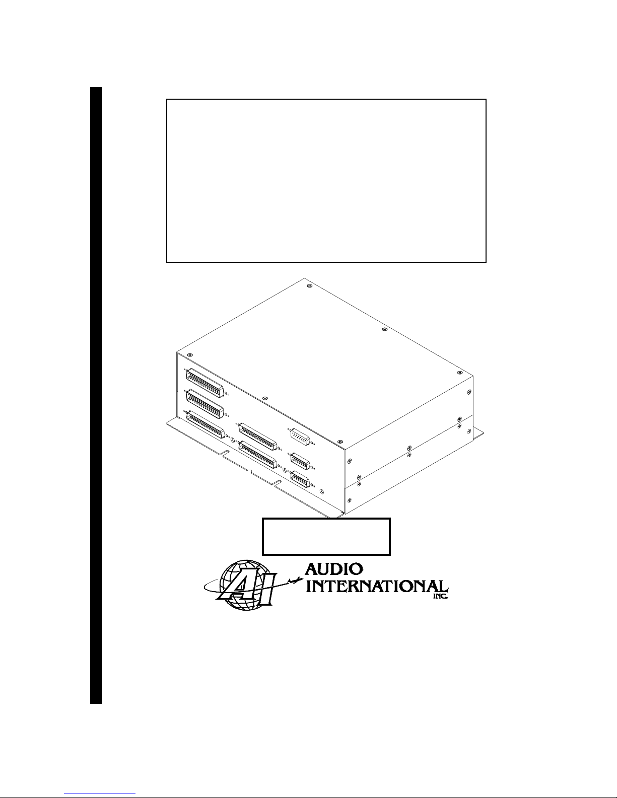
Audio International, Inc. AV-4595-0x-x Installation & Operation
Document #540158, Rev IR, 10/1999 Page 3 of 18
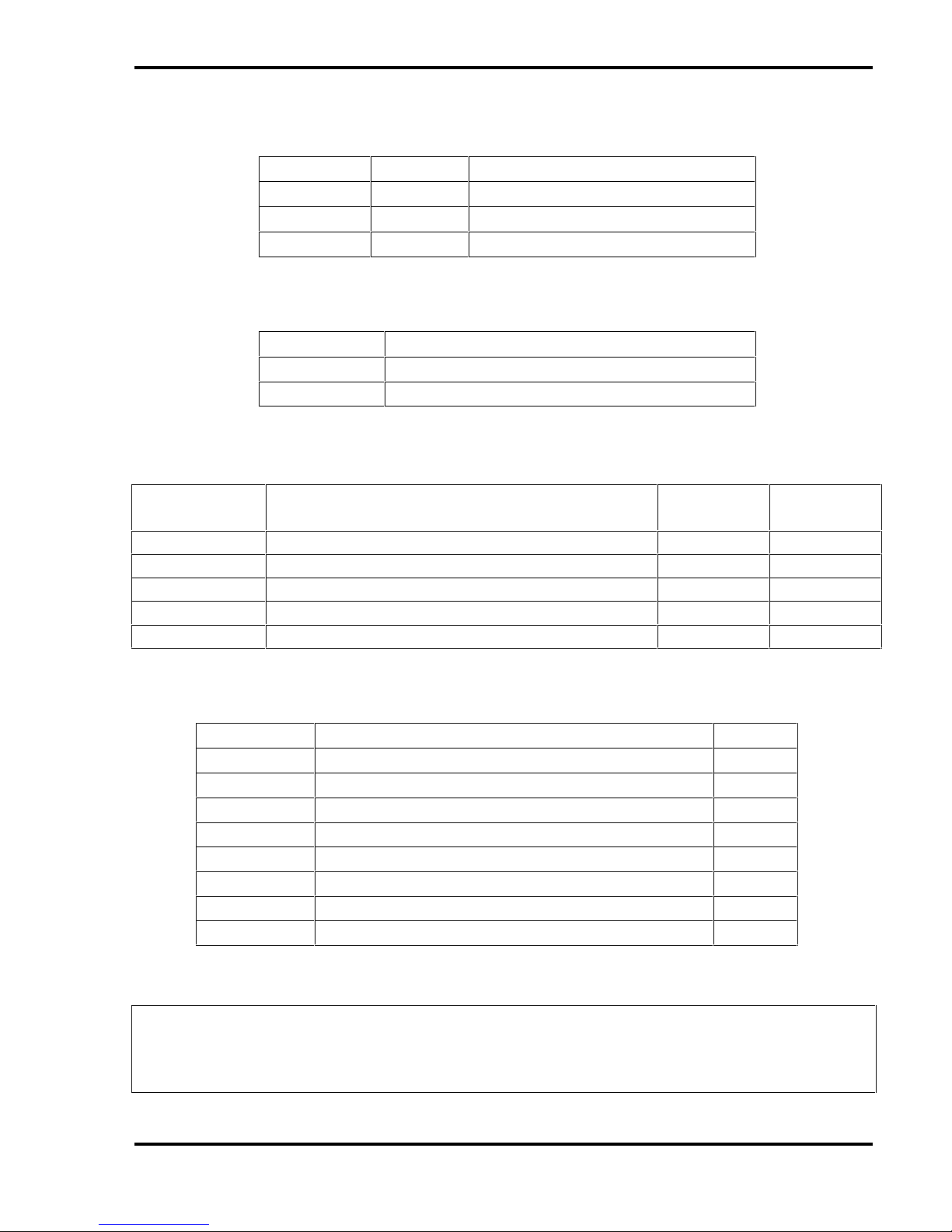
Table of Contents
Section Description Page
1.0 General Information . . . . . . . . . . . . . . . . . . . . . . . . . . . . . . . . . . . . 4
1.1 Introduction . . . . . . . . . . . . . . . . . . . . . . . . . . . . . . . . . . . . . . . . . . . 4
1.2 Purpose of the Equipment . . . . . . . . . . . . . . . . . . . . . . . . . . . . . . . . 4
1.3 Functional Testing. . . . . . . . . . . . . . . . . . . . . . . . . . . . . . . . . . . . . . . 4
1.4 Features . . . . . . . . . . . . . . . . . . . . . . . . . . . . . . . . . . . . . . . . . . . . . . 4
2.0 Application . . . . . . . . . . . . . . . . . . . . . . . . . . . . . . . . . . . . . . . . . . . 5
2.1 Introduction . . . . . . . . . . . . . . . . . . . . . . . . . . . . . . . . . . . . . . . . . . . 5
2.2 Typical Application . . . . . . . . . . . . . . . . . . . . . . . . . . . . . . . . . . . . . . 5
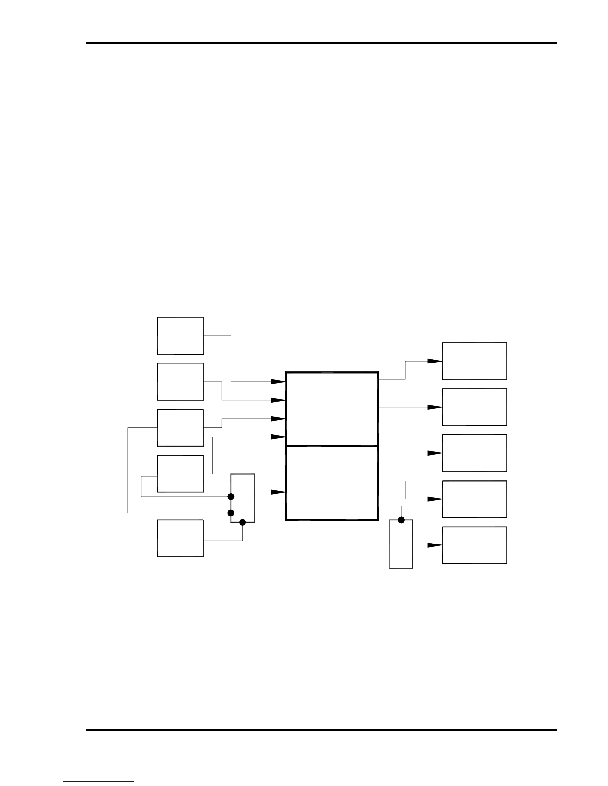
2.3 Block Diagram . . . . . . . . . . . . . . . . . . . . . . . . . . . . . . . . . . . . . . . . . 5
2.4 Multiple Unit Configurations . . . . . . . . . . . . . . . . . . . . . . . . . . . . . . . 6
2.5 Data Bus Control . . . . . . . . . . . . . . . . . . . . . . . . . . . . . . . . . . . . . . . 6
3.0 Installation . . . . . . . . . . . . . . . . . . . . . . . . . . . . . . . . . . . . . . . . . . . 6
3.1 Prior to Installation . . . . . . . . . . . . . . . . . . . . . . . . . . . . . . . . . . . . . . 7
3.2 Unpacking and Inspection . . . . . . . . . . . . . . . . . . . . . . . . . . . . . . . . 7
3.3 Cautions & Warnings . . . . . . . . . . . . . . . . . . . . . . . . . . . . . . . . . . . 7
3.4 Wiring Requirements . . . . . . . . . . . . . . . . . . . . . . . . . . . . . . . . . . . . 7
3.5 Physical Requirements . . . . . . . . . . . . . . . . . . . . . . . . . . . . . . . . . .
. 8
3.6 Electrical Requirements . . . . . . . . . . . . . . . . . . . . . . . . . . . . . . . . . . 8
3.7 Mating Connector Information . . . . . . . . . . . . . . . . . . . . . . . . . . . . . 9
3.8 Pin Out Assignments and Descriptions . . . . . . . . . . . . . . . . . . . . . . 10
3.9 Post Installation Test . . . . . . . . . . . . . . . . . . . . . . . . . . . . . . . . . . . . 14
4.0 Operation . . . . . . . . . . . . . . . . . . . . . . . . . . . . . . . . . . . . . . . . . . . . 14
4.1 Power Up . . . . . . . . . . . . . . . . . . . . . . . . . . . . . . . . . . . . . . . . . . . . 14
4.2 Source Switching . . . . . . . . . . . . . . . . . . . . . . . . . . . . . . . . . . . . . . . 14
5.0 Troubleshooting . . . . . . . . . . . . . . . . . . . . . . . . . . . . . . . . . . . . . . . 14
5.1 Introduction . . . . . . . . . . . . . . . . . . . . . . . . . . . . . . . . . . . . . . . . . . . 14
5.2 General Troubleshooting Procedures . . . . . . . . . . . .. . . . . . . . . . . . 15
5.3 Troubleshooting Chart . . . . . . . . . . . . . . . . . . . . . . . . . . . . . . . . . . . 15
6.0 Specifications . . . . . . . . . . . . . . . . . . . . . . . . . . . . . . . . . . . . . . . . 16
6.1 Unit Specifications . . . . . . . . . . . . . . . . . . . . . . . . . . . . . . . . . . . . . . 16
7.0 Reference Drawings . . . . . . . . . . . . . . . . . . . . . . . . . . . . . . . . . . . . 17
7.1 Dimensions. . . . . . . . . . . . . . . . . . . . . . . . . . . . . . . . . . . . . . . . . . . . 17
7.2 Connections . . . . . . . . .. . . . . . . . . . . . . . . . . . . . . . .. . . . . . . . . . . . 18


 User manual")