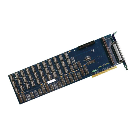
Audio Precision PSIA-2722 User manual


PSIA-2722
User’s Manual
Installation and Operation of the Audio Precision
Programmable Serial Interface Adapter

No part of this manual may be reproduced or transmitted in any
form or by any means, electronic or mechanical, including
photocopying, recording, or by any information storage and
retrieval system, without permission in writing from the
publisher.
Audio Precision®, System One®, System Two™, System Two
Cascade™, System One + DSP™, System Two + DSP™, Dual
Domain®, FASTTEST®, APWIN™, 2700 Series, AP2700,
ATS™ and ATS-2™are trademarks of Audio Precision, Inc.
Windows is a trademark of Microsoft Corporation.
Published by:
5750 SW Arctic Drive
Beaverton, Oregon 97005
Tel: 503-627-0832
Fax: 503-641-8906
US Toll Free: 1-800-231-7350
email: [email protected]
Web: audioprecision.com
Printed in the United States of America
Copyright Ó2002-2005 Audio Precision, Inc.
All rights reserved.
Audio Precision part number 8211.0159 Rev 1
V0126110928

Contents
Safety Information .............................. v
Safety Symbols ............................... vi
Chapter 1
Introduction ................................. 1
Capabilities ................................. 2
Transmitter and Receiver ......................... 2
Data and Clock ports ........................... 2
Data settings ............................... 3
Voltage levels ............................... 3
Documentation................................ 4
Chapter 2
Installation and Setup ........................... 5
PSIA-2722 Components ........................... 6
Power Supply ............................... 6
PN 4540.0020.............................. 6
PN 4540.0051.............................. 7
Connecting the PSIA to the instrument ...................7
Chapter 3
Converter Testing.............................. 9
Relationship between PSIA and the instrument ..............10
PSIA Transmitter and Receiver Connections ................11
Connect an oscilloscope ......................... 11
Connections for Loop-Back configuration ................11
Connections for ADC testing ....................... 13
Connections for DAC testing ....................... 14
Connections for SRC testing ....................... 15
The Transmitter and Receiver panels ...................17
Transmitter and Receiver Settings .................... 18
PSIA-2722 User’s Manual i

Duplicated Controls and Displays .................... 19
Channel Data Assignment ........................ 20
One-click I2S bus settings ........................ 20
Transmit Data Clock Edge ........................ 21
PreEmphasis (Transmitter only) ..................... 22
DeEmphasis (Receiver only)....................... 22
Scale Freq. by .............................. 22
Audio frequency scaling ........................ 22
Rate Ref ................................. 22
Channel Data .............................. 23
Bits per channel display ........................ 23
MSB first: Transmitter ......................... 24
MSB first: Receiver .......................... 24
Data and padding controls ....................... 25
Data.................................. 25
Pads .................................. 25
Left and Right Justify: Transmitter ................... 26
Left and Right Justify: Receiver .................... 26
Pad bits logic states (Transmitter only) ................26
Data Bit Indicators ........................... 26
The Clocks control matrix ........................ 27
The Clock signals ........................... 27
The Clock controls ............................ 27
Direction ................................ 28
Bit Clock Edge Sync (Frame Clock and Channel Clock)........28
Invert Waveform (Frame, Channel and N*Fs Clocks) .........28
Shift One Bit Left (Frame Clock Only) ................. 29
Bit Wide Pulse (Frame Clock and Channel Clock)...........30
PSIA Clock Rate and Factor Settings .................30
Frame Clock (Fs) Rate Setting .................... 31
Channels per Frame .......................... 31
Setting the Bits per Channel ....................... 32
N, the N*Fs multiplier .......................... 32
M, the Master Clock multiplier ...................... 33
Jittering the Master Clock ........................ 33
Computed Clock Rate Displays ..................... 33
Logic Voltage controls .......................... 34
PSIA Quick Setup Guide .......................... 34
Common converter testing configurations ................. 36
PSIA Transmitter: Frame, Bit & Master Clock OUT ...........36
PSIA Transmitter: Frame & Bit Clock OUT, Master Clk IN ........36
PSIA Receiver: Frame, Bit & Master Clock OUT .............37
PSIA Receiver: Frame & Bit Clock OUT, Master Clock IN ........37
ii PSIA-2722 User’s Manual

Appendix A
Miscellany ................................. 39
PSIA Abbreviations and Terms ....................... 39
Oscilloscope Examples........................... 40
N*Fs Table ................................. 42
Using INTERVU with PSIA-2722 ...................... 42
Appendix B
Configuration Examples and Files ...................43
Eval boards and sample files ........................ 43
Appendix C
Connection Guidelines .......................... 45
General Guidelines ............................. 45
Oscilloscope Monitoring .......................... 45
Triggering ................................ 46
Oscilloscope Connections ........................ 46
Appendix D
Specifications ............................... 47
DC Characterisics ............................. 47
DC characteristics, no load........................ 47
PSIA input / output impedance ...................... 47
AC characteristics ............................. 48
Maximum clock frequency ........................ 48
Output latency, Clock to Out ....................... 48
Setup and Hold, inputs .......................... 49
User test jacks .............................. 49
APIB .................................... 49
APIB configuration maximums ...................... 49
Appendix E
AP Basic Extensions for PSIA ..................... 51
PSIA-2722 User’s Manual iii

:
iv PSIA-2722 User’s Manual

Safety Information
Do NOT service or repair this product unless properly qualified. Servicing
should be performed only by a qualified technician or an authorized Audio
Precision distributor.
One of two external power supplies is provided with this product:
The power supply PN 4540.0020 is designed to operate only from an AC
power source (100 V–240 V rms, 47 Hz–63 Hz) with an approved three-con-
ductor power cord and safety grounding. Do NOT defeat the safety ground
connection.
The power supply PN 4540.0051 is designed to operate only from an AC
power source (100 V–240 V rms, 50 Hz–60 Hz). This power supply has an in-
tegral 2-conductor mains plug.
Either power supply automatically adjusts to the line voltage and frequency
within the specified range. No user adjustments are necessary. Neither of the
power supplies nor the PSIA-2722 contain user-replaceable fuses.
Use only the AP power supply PN 4540.0020 or PN 4540.0051 with the
PSIA-2722. The use of other power supplies may result in damage to the
PSIA-2722, electrical shock hazard from the power supply or the PSIA-2722,
and loss of fire hazard protection.
This product and power supply are for indoor use ONLY.
PSIA-2722 User’s Manual v

Safety Symbols
The following symbols may be marked on the panels or covers of equip-
ment or modules, and may be used in this manual:
WARNING!—This symbol alerts you to a potentially hazardous condition,
such as the presence of dangerous voltage that could pose a risk of electrical
shock. Refer to the accompanying Warning Label or Tag, and exercise extreme
caution.
ATTENTION!—This symbol alerts you to important operating consider-
ations or a potential operating condition that could damage equipment. If you
see this marked on equipment, consult the User’s Manual or Operator’s Man-
ual for precautionary instructions.
FUNCTIONAL EARTH TERMINAL—This symbol marks a terminal that
is electrically connected to a reference point of a measuring circuit or output
and is intended to be earthed for any functional purpose other than safety.
PROTECTIVE EARTH TERMINAL—This symbol marks a terminal that
is bonded to conductive parts of the instrument. Confirm that this terminal is
connected to an external protective earthing system.
vi PSIA-2722 User’s Manual

Chapter 1
Introduction
The PSIA-2722 Programmable Serial Interface Adapter is an accessory unit
for Audio Precision’s System Two Cascade, Cascade Plus and 2700 Series
digitally-capable instruments. Since the PSIA operations for all these systems
are identical, in this manual the designation “instrument” indicates any of the
above models.
When used without a serial interface adapter, the instrument can provide
AES3 and IEC60958 serial digital inputs and outputs at a wide range of sam-
ple rates and resolutions, as well as parallel digital inputs and outputs. A serial
interface adapter such as PSIA-2722, however, is required to transmit or re-
ceive digital signals and associated clock inputs and outputs for non-AES3/
IEC60958 serial formats often encountered in telecommunications and con-
verter design and testing.
The PSIA-2722 is similar in capability to the earlier Audio Precision SIA-
2322, with a key difference: the PSIA-2722 is software controlled. Where con-
figuring the SIA-2322 involved the manual setting of a number of DIP
switches for each test setup, PSIA-2722 is configured from the PSIA panel in
the instrument control software. The setting of master clock rate, N*Fs clock
rate, bit rate, number of channels, word length and sample rate is more intu-
itive and is aided by automatic calculations. Each test configuration is now
PSIA-2722 User’s Manual 1
Figure 1. The Audio Precision PSIA-2722 Programmable Serial Interface Adapter.

saved as part of the instrument test file. Setups for specific converters can be
loaded from previous tests or imported from sample files.
The PSIA-2722 must be connected to an Audio Precision instrument run-
ning the appropriate control software:
§For System Two Cascade and System Two Cascade Plus instruments, the
control software must be APWIN version 2.22 or 2.24, or AP2700. We
strongly recommend AP2700 version 3.10.
§For a 2700 Series instrument, the control software must be AP2700.We
strongly recommend AP2700 version 3.10.
AP2700 control software is available by download from the Audio Preci-
sion Web site at audioprecision.com.
The instrument parallel digital output and input provide data connections
for the PSIA; additional cables connect the instrument master clock and the
APIB control bus to the PSIA-2722. The PSIA is powered by a separate
5 VDC power supply.
The PSIA provides all necessary serial input, output and clock ports for de-
vice connection, as well as provision for oscilloscope monitoring of the vari-
ous signals. The voltage levels of all the PSIA ports can be set to
accommodate devices from different logic families.
Capabilities
Transmitter and Receiver
PSIA-2722 has a serial transmitter section for testing devices with digital
input, such as DACs; and a serial receiver section for testing devices with digi-
tal output, such as ADCs. Each section is configurable to a wide range of
clock and data settings, using either internal or external clock references.
The transmitter and receiver sections can also be operated simultaneously
for SRC or other testing. When the instrument’s internal master clock is used
as the only clock in this configuration, the clock rates of the two sections are
tightly coupled. When this configuration is used with a second, external master
clock (typical of SRC testing), the controls and functions of the transmitter and
receiver are almost entirely independent.
Data and Clock ports
The transmitter and receiver sections each have ports and software panel
controls for
§Data
§Frame Clock
Chapter 1: Introduction Capabilities
2 PSIA-2722 User’s Manual

§Channel Clock
§Bit Clock
§N*Fs Clock
§Master Clock
Within certain constraints, the clocks can be set to a wide selection of rates.
For SRC testing, transmitter and receiver clocks can be set to different rates
when a second master clock frequency is provided. Configuration of clock sig-
nal polarity, edge sync, pulse width and sync relation to data is available where
appropriate.
The Master Clock, Bit Clock and Frame Clock ports can be configured as
inputs or outputs, enabling independent selection of master or slave mode for
receiver and transmitter.
Data settings
For transmission, the data are provided from the instrument as determined
by the Digital Generator and Digital I/O settings, and the PSIA configures this
data in a serial stream for the device under test (DUT).
For reception, the serial stream comes from the DUT, and the PSIA must be
set to match the incoming data configuration.
The arrangement of the data within the serial word can be set or matched by
adjusting four parameters:
§The data length in bits,
§The padding bits before and after the data (if any),
§The state of the padding bits,
§The order of the data bits (MSB or LSB first).
Also, the timing relationship between the data and the bit clock (synchro-
nized on the rising or falling edge) can be set.
Voltage levels
PSIA clock and data ports can be set to interface with common logic fami-
lies:
§5.0 V TTL
§3.3 V TTL
§3.3 V CMOS
§2.4 V CMOS
§1.8 V CMOS
Capabilities Chapter 1: Introduction
PSIA-2722 User’s Manual 3

Documentation
This PSIA-2722 User’s Manual is the primary document for the PSIA. Con-
verter testing also requires a good understanding of many of the functions of
the Audio Precision instrument; these are covered in detail in the instrument’s
User’s Manual.
Context-sensitive Help information for the PSIA is included within the con-
trol software.
Visit the Audio Precision Web site at audioprecision.com for more informa-
tion on using the PSIA.
Chapter 1: Introduction Documentation
4 PSIA-2722 User’s Manual

Chapter 2
Installation and Setup
The PSIA-2722 is an accessory to Audio Precision’s System Two Cascade,
Cascade Plus and 2700 Series digitally-capable instruments. Since the PSIA
operations for all these systems are identical, in this manual the designation
“instrument” indicates any of the above models.
The PSIA-2722 must be connected to an Audio Precision instrument run-
ning the appropriate control software:
§For System Two Cascade and System Two Cascade Plus instruments, the
control software must be APWIN version 2.22 or 2.24, or AP2700. We
strongly recommend AP2700 version 3.10.
§For a 2700 Series instrument, the control software must be AP2700.We
strongly recommend AP2700 version 3.10.
PSIA-2722 User’s Manual 5
Figure 2. PSIA-2722 and a System Two Cascade Plus.

AP2700 control software is available by download from the Audio Preci-
sion Web site at audioprecision.com.
See your instrument Getting Started manual for information on setting up
your Audio Precision instrument.
PSIA-2722 Components
When you open the shipping box you will find:
§The PSIA-2722 chassis.
§A 5 VDC external universal mains power supply, selected for your
location; either PN 4540.0020 or PN 4540.0051. The power supply
output cord is attached to the PSIA-2722 chassis.
§If your power supply is PN 4540.0020, there will be a mains cable for
the power supply. Power supply PN 4540.0051 has an integral mains
plug.
§An APIB cable. This cable is for exchange of control data between the
PSIA, the instrument and the controlling PC.
§Two 25-wire parallel digital cables. These are used for digital data
communications between the PSIA and the instrument.
§Four 50 Wcoax cables each fitted with BNC connectors on both ends.
These are used for instrument Master Clock connection and for “Loop-
Back” testing.
§Two cable harnesses, each of six 50 Wcoax cables fitted with BNC
connectors on one end and dual square pin connectors on the other.
These are used for connection to the DUT.
§This manual.
Power Supply
Use only the power supply provided by Audio Precision (AP part number
4540.0020 or 4540.0051) for powering the PSIA. There is no user-replaceable
fuse for either power supply.
PN 4540.0020
The PN 4540.0020 DC power supply accommodates mains voltages from
100 VAC to 240 VAC and mains frequencies from 47 Hz to 63 Hz. Maximum
current consumption is 0.4 A.
If the power supply ON indicator (a green LED near the AP label) does not
light when AC mains power is applied to the DC power supply, verify that the
Chapter 2: Installation and Setup PSIA-2722 Components
6 PSIA-2722 User’s Manual

mains power cord is functioning properly. If the ON indicator still does not
light, contact Audio Precision for a replacement supply.
PN 4540.0051
The PN 4540.0051 DC power supply accommodates mains voltages from
100 VAC to 240 VAC and mains frequencies from 50 Hz to 60 Hz. Maximum
current consumption is 1.0 A.
Connecting the PSIA to the instrument
Place the PSIA near both the instrument and the device that you want to
test. Using an APIB cable, connect the instrument to a PC that has AP2700 (or
APWIN version 2.22 or 2.24) installed.
Be sure the mains power is OFF for both the instrument and the PSIA. Then
connect the four cables between the instrument and the PSIA following these
instructions. See Figure 3.
Connecting the PSIA to the instrument Chapter 2: Installation and Setup
PSIA-2722 User’s Manual 7
Figure 3. PSIA-2722-to-instrument rear-panel system interconnections.

§Attach the APIB cable from one of the PSIA APIB connectors to the
unused APIB connector on the instrument rear panel.
§Connect a 50 WBNC cable from the instrument MASTER CLOCK
OUT BNC connector to the PSIA rear-panel jack labeled FROM
MASTER CLK OUT.
§Connect one 25-wire parallel digital cable from the instrument
PARALLEL OUTPUT to the PSIA connector labeled FROM
PARALLEL OUTPUT.
§Connect the second 25-wire parallel digital cable from the instrument
PARALLEL INPUT to the PSIA connector labeled TO PARALLEL
INPUT.
Finally, insert the 5.5 mm coaxial plug from the 5 VDC power supply into
the POWER jack on the rear of the PSIA, and plug the mains power cord into
the electrical mains supply. This will power up the PSIA and light the OUT/IN
and LOGIC VOLTAGE SUPPLY LEDs.
Switch the instrument ON and launch the control software.
If an APIB cable is connected between the instrument and
the PSIA but the PSIA is not powered ON, the control
software will start in Demo Mode. Be sure that the PSIA is
ON when starting the control software with the APIB cable
connected.
If you connect the PSIA to the instrument after the control software has
been launched, choose Utilities > Restore Hardware to enable the software
to recognize the presence of the PSIA.
All four instrument-to-PSIA cables must be connected for the
PSIA to operate properly.
Chapter 2: Installation and Setup Connecting the PSIA to the instrument
8 PSIA-2722 User’s Manual

Chapter 3
Converter Testing
PSIA-2722 is designed to enable testing of audio analog-to-digital convert-
ers (ADCs), digital-to-analog converters (DACs) and other digital devices that
have data or clock characteristics that are not compatible with the AES3 /
IEC60958 (also called AES/EBU and SPDIF) digital serial interface standards.
The AES3 and IEC60958 standards limit the audio data word length and
format, number of channels, sample rates, and sychronization relationships to
PSIA-2722 User’s Manual 9
Figure 4. PSIA-2722 with Audio Precision instrument and coverter test fixture.

a narrow range of choices. These standards also specify the addition of
metadata and the superimposition of clock rate and data into one stream by use
of bi-phase mark encoding.
The PSIA transmitter and receiver are unconstrained by these standards.
Each section has five clock ports and one data port, enabling common three-
or four-wire serial interfacing. Each section can be operated in a master or
slave relationship with the DUT. Clock relationships and clock-to-data rela-
tionships are variable, and with an additional master clock generator the trans-
mitter and receiver sections can be set to different sample rates for SRC
testing.
This chapter provides an overview of digital converter testing with an Au-
dio Precision instrument and the PSIA-2722, including connection diagrams
and PSIA software panel operation. Examples of actual converter setups are
detailed on the Audio Precision Web site. See Appendix B for more informa-
tion about test configuration examples and sample files.
Relationship between PSIA and the
instrument
The PSIA-2722 has no function without an Audio Precision instrument. All
signal generation and analysis, DSP processing, and computer control opera-
tions such as file handling, data display, etc., are performed by the instrument.
The instrument digital or analog audio generators and analyzers selected for
a particular test will be used with the PSIA in the same way that they would be
in testing using the AES3 interface, but PSIA functions replace the instru-
ment’s internal AES3 transmitter/receiver.
See Chapter 2 for information on interconnecting the instrument hardware
with the PSIA.
The control software provides two PSIA software panels for serial interface
operation. Click on the PSIA Transmitter (green) or PSIA Receiver (red) but-
tons on the Toolbar, or choose Panels > PSIA Transmitter or Panels > PSIA
Receiver on the Main menu or press Ctrl-T or Ctrl-R to open the panels.
Next open the DIO panel by clicking the DIO button or by choosing Panels
> Digital Input/Output. Enable PSIA operation for input or output by select-
ing PSIA as the DIO Input: Connector or Output: Connector (APWIN: In-
put: Format or Output: Format) setting.
A number of DIO panel controls and displays also affect the PSIA; for con-
venience, some of these controls and displays are duplicated on the PSIA pan-
els. See Duplicated Displays and Controls on page 19.
Chapter 3: Converter Testing Relationship between PSIA and the instrument
10 PSIA-2722 User’s Manual
Table of contents
Other Audio Precision Adapter manuals

