Audio Technica ATW-A410P User manual

User Manual
UHF Powered Wideband Antenna
ATW-A410P

1
Introduction
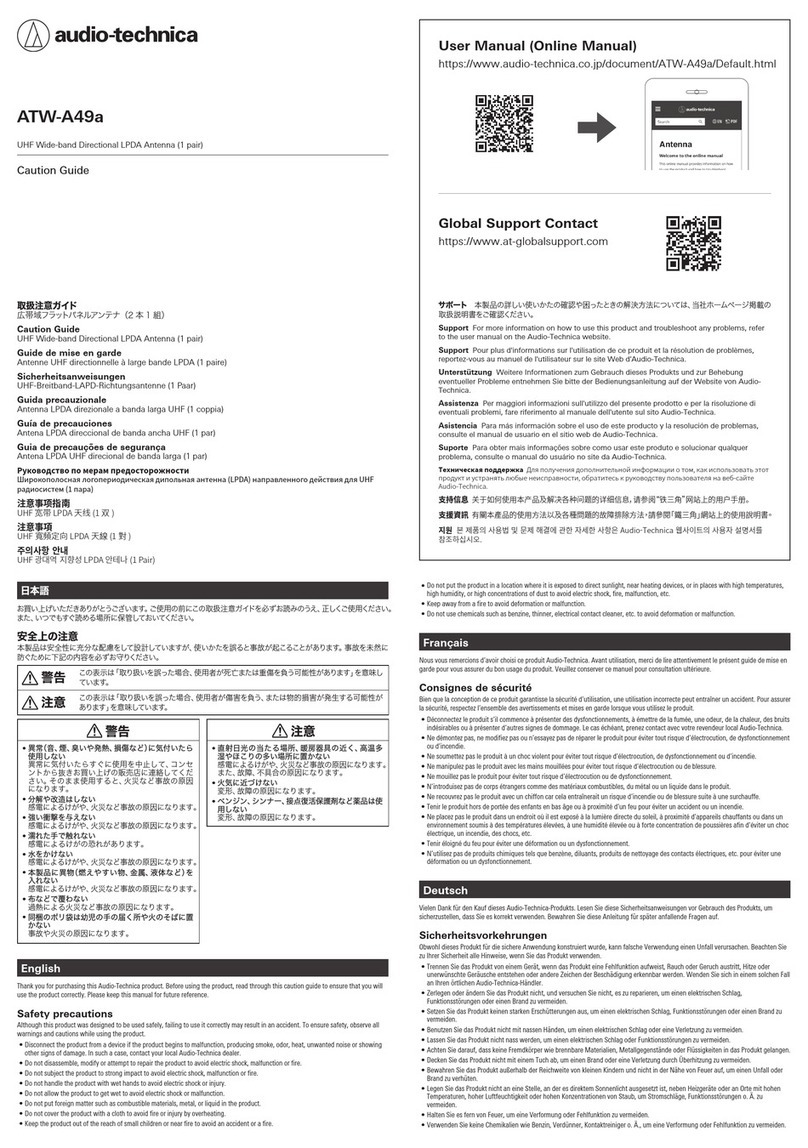
Thank you for purchasing this Audio-Technica product. Before using the product, please read through the Quick Start Guide, as well as this user
manual when necessary, to ensure that you use the product correctly.
Safety precautions
Although this product was designed to be used safely, failing to use it correctly may result in an accident. To ensure safety, observe all warnings and
cautions while using the product.
• Disconnect the product from a device if the product begins to malfunction, producing smoke, odor, heat, unwanted noise or showing other signs
of damage. In such a case, contact your local Audio-Technica dealer.
• Do not disassemble, modify or attempt to repair the product to avoid electric shock, malfunction or fire.
• Do not subject the product to strong impact to avoid electric shock, malfunction or fire.
• Do not handle the product with wet hands to avoid electric shock or injury.
• Do not allow the product to get wet to avoid electric shock or malfunction.
• Do not put foreign matter such as combustible materials, metal, or liquid in the product.
• Do not cover the product with a cloth to avoid fire or injury by overheating.
• Keep the product out of the reach of small children or near fire to avoid an accident or a fire.
• Do not put the product in a location where it is exposed to direct sunlight, near heating devices, or in places with high temperatures, high
humidity, or high concentrations of dust to avoid electric shock, fire, malfunction, etc.
• Keep away from a fire to avoid deformation or malfunction.
• Do not use chemicals such as benzine, thinner, electrical contact cleaner, etc. to avoid deformation or malfunction.

2
Notes on use
• Be sure to read the connected device’s user manual before use.
• Turn off the power of the connected device before connecting or disconnecting cables.
• If you use the product near a TV or radio antenna, you may hear unwanted noise in the television or radio. If this occurs, move the product away
from the device.
Notes on installation
• Install the product where there is a clear line of sight from the
transmitter. Do not install the product behind interior decoration
elements.
• Audio-Technica accepts no responsibility for accidents such as
falling that come as a result of improper installation.
• Install the product in a place where the antenna will not be
damaged by moving people or equipment.
• Do not install the product where unwanted noise is received from
devices such as light dimmers, fluorescent lighting, LED lighting,
large motors, office automation equipment such as computers, or
electronic musical instruments.
• Do not install the product close to devices such as wireless LAN
routers. This may result in unwanted noise.
• For best RF performance of the connected diversity receiver, install
the antennas at least 1 m (3.3') apart.
Maintenance
• If the product becomes dirty or covered with dust, be sure to turn off the connected device before wiping the product off with a dry and soft cloth.
• Do not use benzine, thinner or electrical contact cleaner, etc. They may deform or otherwise damage the product, or cause operational failure.
Install the product where
there is a clear line of
sight from the transmitter
Space antennas at least
1 m (3.3') apart
Keep the product away from
windows (install the product
where it does not pick up
unwanted radio noise)
Install the product in a place
where the product is not disturbed
by people or equipment

3
Part names and functions
+12
+6
-
10 0 dB
❶ Mounting bracket removal button
❷ Gain indicator
❸ Gain selector switch
❹ BNC output terminal
❺ Cable tie mounting hole
You can secure the main unit and bracket with a cable tie (sold separately).
❻ Mounting bracket
❷❶ ❶❹ ❺ ❻❸

4
Installation
Positioning Antennas for Diversity Reception (when mounting to the wall)
In order to optimize diversity reception for different types of transmitters, it is necessary to position the product with appropriate orientation. Refer
to the information below when positioning the product.
When mounting the product to the ceiling, refer to "Polar pattern" (p.10).
Handheld and body-pack transmitters Boundary microphone and microphone stand
transmitters
Mixed transmitter types
Vertical Horizontal Vertical and horizontal

5
Installation
BNC cable wiring pattern
There are 3 patterns of BNC cable wiring. Wire according to the installation environment.
• Use “HEX14” for BNC nut size.
• Tighten the BNC nut until it is snug. Failure to do so may damage the main unit.
Wiring from the side
Wiring from the top
Wiring from the back

6
Installation
Mounting/removing the product
Mounting
• When using an electric screwdriver, make sure to use one with a clutch.
• Set the torque to the minimum setting and tighten the screws carefully to avoid deformation. If you tighten the screws too much, the mounting
bracket may be damaged.
• When using 3.5 mm diameter or #6 screws, use a washer.
1. Use the included wood screws to mount the bracket to the wall.
2. Install the main unit into the bracket.
3. Push the main unit until the mounting bracket removal button on each side clicks.
4. Make sure that the main unit is securely fixed in place.
• The main unit is not fixed firmly if either of the mounting bracket removal buttons is pushed in.
5. After installation is complete, attach the BNC cable to a wireless receiver.
Wall or ceilingWall or ceiling
Electrical box, outlet box,
etc.
When using an electrical box to mount the product to the wall
Mounting bracket removal buttons

7
Installation
Removing
1. Push the mounting bracket removal button on each side of the bracket.
2. Remove the main unit from the bracket.
Mounting bracket removal buttons

8
Gain switch settings
Consider environmental factors such as cable loss and the receiver’s reception level when selecting the gain settings.
-10 dB When the reception level is sufficiently high, it is possible to reduce potential interference and noise from adjacent
channels. Please note that this reduces the reception level, therefore reducing the range in which the wireless
microphone can function.
0 dB (default) The signal will receive no additional gain. Use this setting when the receiver’s reception level is sufficiently high.
+6 dB, +12 dB Use this to compensate for cable loss. Cable loss varies depending on the cable type, frequency and length; refer
to the table below when choosing the appropriate settings.
470 to 530
MHz
530 to 590
MHz
590 to 650
MHz
650 to 700
MHz
727 to 787
MHz
795 to 806
MHz
806 to 810
MHz
821 to 865
MHz
925 to 938
MHz
946 to 950
MHz
+6 dB
RG58
(3D-2 V) 18.1 m 17.1 m 16.2 m 15.5 m 14.7 m 14.3 m 14.2 m 13.9 m 13.2 m 13.1 m
RG5
(5D-2 V) 31.4 m 29.7 m 28.2 m 26.9 m 25.5 m 24.8 m 24.7 m 24.2 m 23.0 m 22.8 m
RG8
(8D-2 V) 42.4 m 40.1 m 38.1 m 36.4 m 34.5 m 33.5 m 33.4 m 32.7 m 31.1 m 30.8 m
+12 dB
RG58
(3D-2 V) 36.2 m 34.2 m 32.4 m 31.0 m 29.4 m 28.6 m 28.4 m 27.8 m 26.4 m 26.2 m
RG5
(5D-2 V) 62.8 m 59.4 m 56.4 m 53.8 m 51.0 m 49.6 m 49.4 m 48.4 m 46.0 m 45.6 m
RG8
(8D-2 V) 84.9 m 80.2 m 76.2 m 72.8 m 69.0 m 67.1 m 66.8 m 65.4 m 62.2 m 61.6 m

9
Dimensions
Main unit
Mounting bracket
+12
+6
-
10 0 dB
45.8
83
83.5
46
44.5
106
105
60
89
70
68.5
66.7
4.4
9.6
21
28
155.3
4.4
9.6
4.4
4.4
9.6
152.4
φ4.4
φ9.6
φ4.4
φ9.6
φ4.4
175
17550
(Unit: mm)
(Unit: mm)

10
Polar pattern
Side view Top view
Rear view
+12+6
-
10 0 dB
90°
60°
30°
0°
120°
150°
180°
150°
120°
90°
60°
30°
-5dB-10dB-15dB-20dB
90°
60°
30°
90°
60°
30°
0°
120°
150°
120°
150°
180°
-20dB
-15dB
-10dB
-5dB
-6dB
60°
90°
60°
30°
0°
30°
60°
90°
-6dB
30°
-6dB
0°
30°
60°
-6dB

Specifications
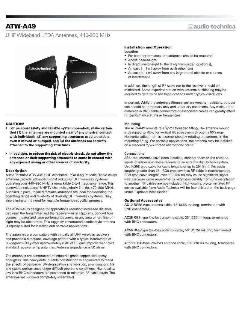
Frequency range 470 to 990 MHz
Connector BNC-J
Impedance 50 ohms
Power requirement +12V DC, 60 mA or less
OIP3 30 dBm or higher
Signal gain -10 dB/0 dB/+6 dB/+12 dB
Operating temperature range -10º C to 50 ºC
Dimensions 175 (6.9”) mm × 175 (6.9”) mm × 50 (2.0”) mm (without mounting bracket)
Weight 390 g (13.8 oz) (without mounting bracket)
Accessories Bracket, Wood screw×4
For product improvement, the product is subject to modification without notice.
Audio-Technica Corporation
2-46-1 Nishi-naruse, Machida, Tokyo 194-8666, Japan
www.audio-technica.com
©2019 Audio-Technica Corporation
Global Support Contact: www.at-globalsupport.com
ver.1 2019.05.01
ver.2 2019.08.15232417140-02-02
Table of contents
Other Audio Technica Antenna manuals