manuals.online logo
Brands
  1. Home
  2. •
  3. Brands
  4. •
  5. AUDIO TELEX
  6. •
  7. Mixer
  8. •
  9. AUDIO TELEX TX6000 User manual

AUDIO TELEX TX6000 User manual

AUlilDilril@ IHil
COMMUNICATIONSPTYLYD
p
L
: ' ..:.:::::::::::::::::::: "
H
ffi
s
b
-
u
J
ru
^::::::.:,,,,:, :,,,41
u
ffiffiG'Hff.,0
A
AIIIB^IIAililADE, 3
O-t
Erkrd
"?!FH
Audio Telex Communications Pty Ltd
ACN 001345482 lncorporated ln NSW
149 Beaconsfteld Street
Prlvate Bag 149
Sllverwater NSW 2128
Australla
Ph 02 96471411
Fax 02 9648 3698
42 Commercial Road
PO Box 871
Fortltude Valley QLD 4006
Ph 07 38521312
Fax 07 32521237
2U277 tlddleborough Road
Box Hlll VIC 3128
PO Box 151
Blackburn South VIC 3130
Ph 03 9890 7477
Fax 03 9890 7977
7164-66 Kent Street
PO Box 489
Cannlngton WA 6107
Ph 08 9356 2761
Fax 08 9356 2762
Electronlc Concepts Pty Ltd
76 George Street
Thebarton SA 5031
PO Box 7034 Hutt Street
Adelaide SA 5000
Ph 08 82349444
Fax 08 82349441
K W McOulloch Pty Ltd
54a Albert Road
iloonahTAS 7009
Ph 03 6228 6373
Fax 03 6278 1063
Unlt B, 11 Plermark Drlve
PO Box 512
Albany NZ 1331
Ph 09 415 9426
Fax 09 415 9864
TX6000
6 Channel Mixer
Product Description
The TX6000 is a 6 channel audio mixer that operates from 240 VAC @ 50 FIz (or I l0 VAC @ 60 llzwith factory modification) a
24 WC via an extemal battery supply. The TX6000 is I standard rack unit high (a4mn) and has a standard rack width of 482mm.
For table mounting rubber feet are supplied but these can be removed if rack mounting is intended. Featuring six dual purpose inputs
consisting of XLR balanced mic inputs and dual RCA aux/line level inputs. Channel 6 has a high€r aux/line level input sensitivity to
enable it to accept a CD player or similar high level input sigrral.
Front Panel Controls
l. Dual ilicrophone/Line Gain Gontrols: The 6 dual mic/line input contols are marked Ch I thoireh Ctr 6 and
strould be adjusted to provide the required mix level for each individual channel. Start with the contols set to level g-and turn thl
controls slowly clockwise until the desired mix for eactr ctrannel is obtained.
Bass Tonal Control: Setting this contol in the cente "zero" position will give an overall flat bass respoirse to the output
of the amplifier. Adjusting the bass contol in a clockwise direction will provide up to +12 dB of bass boost @ 100 Hz. Adjusting
he bass c.uttol in a counter-clockwise directisr will provide up to -12 dB of bass cut @ 100 Hz.
Treble Tonal Control: Seting this contol in the centre "zero" position will give an overall flat teble response to the
output of the amplifio. Adjusting the treble contol in a clockwise direction will provide up to +9 dB of teble boost 6 l0 kHz.
Adjusting the teble control in a counter-clockwise directiqr will provide up -9 dB of teble cut at l0 kFIz.
U?:tq Output Control: This contol adjusts fte overall output level of the mixer depanding on the levels set for the
individual input mix channels as daailed above. Start wittr the contol level set to level 0 and slowly turn ttre contol clockwise
until the desired output level of the mixer is readred.
Headphone_ Output Socket A l/4- TRS stereo socket is provided for the connection of monitm headphones. The
otrtput level to the headphmes is a nominal 3.5 volts @ 600 ohms and is connected before the mast€r ouput levei controls so
adjusting the output level contols will not effect the headphone outprd level.
POWef SWitCh: This switch contols the switching of the AC power to the mixer. Rocking this switch upwards tr:rns grr AC
power to the mixer while rocking the switch downwards turns pow€r offto ttre mixer. When in the upward'dr" position, the red
neon in the body of the switch will glow.
jjj
jj
3.
4.
5.
6.
O
oiQiA N0l0 Tttil o
OE
-X- rxsooo O
ooooooo
,Pi Qi ',cc o
7' LED Display VU Meter! Marked in decibel graduations from -21 dB to +3 dB, the light emitting diodes will indicate the
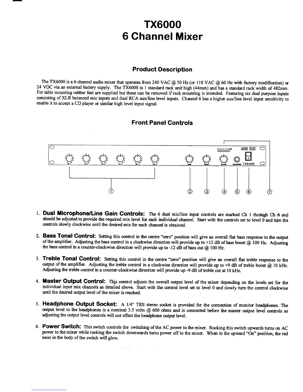
volume level at the output of the mixer. For normal operation the LED's glow green as they modulate with the output level of the
mixer. If the lights are consistently indicating red the mixer is being ovodriven, resulting in distortion in the quality of the audio
sigrral.
Rear Panel Connections
l. 3 Pin IEC AC Mains Power lnlet The operating voltage is 240 VAC @ 50 Hzor I l0 VAC @ 60tuz. The AC power
voltage is not externally user adjustable but is factory preset. The inlet is equippedwith an inbuilt AC fus; holder fitted with a 0.5
amp slow blow fuse plus one spare. Power consumptior is 15 VA. E Pleasc ensure thst the mains power cord is
disconnected before attempting to check or rcplace this fuse.
24 Volts DC Power Source Connection: 2.lmm DC power socket allows for the connection of an exrernal 24
VD.C battery for applications where PA systern operation is imperative. The centre terminal post or pin is for connection to the
positive (+) tenninal. The sleeve is for connection to the negative (-) terminal.
Spare SCrew Tgfminalsl These spare screw terrninals allow the connection of various optiural tone module accessories.
They are not connected to any point in the mixer from the factory and are spare.
!-ilp_Ogtput ude XLR style active balanced isolated output for connection to a power amplifier. provides a maximum of
l.sv RMS output. Suitable for driving power amplifiers or similar devices. Pin connectims are Pin I : Earth. pin 2 = Active
Positive (+). Pin 3 = Active Negative O.
IfpC OUtput 2 x RCA style phono output connector for line level output. Provides a maximurn of 700mV into loK Ohms,
ideal for a connection to most ttrydutd tape recorders. This outptd is sourced before the master gain contol and as sudr the tape
output level is not influenced by the operation of the master gain contol.
MiCfOphOne lnputsl Note: All inputs are universal line / microphone inputs Both connectors can not be utilised for
any one input channel. Six fernale XLR inputs accept 200 Ohm balanced or rmbalanced microphone inputs. Pin connections are
Pin I : Earth. Pin 2 : Active Positive (+). pin 3 : Active Negative O.
Line lnpUts: Note: All inputs are universal line / microphone inputs. Both connectors can not be utilised for any one
input channel. Six pairs of RCA style phono input connectors acc€,pt unbalanced line or auxiliry inputs for channels I through
6. Channel 6 accepts higha level inpus such as a CD player.
IA
AA A
4.
5.
7.
@88@
*$'. rarurururer '6 2\ 6
ornon-*.ur.^**rrr"rW @ QZ @@
@
@
8@@8
Continued ouo p"g. I
Special Facilities
PhantOm POWef: ISVDC is normally supplied to each of the six XLR microphone inputs. An internal link can be fotrnd o
the internal circuit board PCB6220 to disconnect phantom power from all six inputs. g It is necessary to disconnect the powe
cord and remove the lid from the mixer before operating this switch.
Optional Accessories
g The instaltation of some of the following optional accessories involves access to the inside of the mixer. Installatio
should only be attempted by a qualified technician. Always turn off the AC power and remove the AC power cord befor
attempting to access the inside of the mixer. Please contact your nearest Audio Telex ofiice for details of your neares
qualified technician
TOne GenefatOfS: Four separate tones are available as an option via the ATC5488 tone ge,nerator board. This intemalt
mounted PCB is easily fitted and plugs directly into a socket provided on the internal circuit board PCB622| inside the TX6000
Please follow the instructions supplied with the tone generator. When any tone from the ATC5488 PCB is activated all inputs wi1
automatically mute except for input one.
Tones available on the ATC5488 tone generator board are:
Evacuatisr Tone (to Austalian Standard A52220.1.2)
Alert Tone (to Australian Standard 452220.1.2)
Bell Tone
Pre Announce Chime
Voice Operated Muting lUlodules: Vox mute modules are easily fitted intemally into the TX6000 and plug directly int
a socket provided on the internal circuit board PCB622I.
The model numbers of the two different modules available are:
TX30l0 Muting Module. Provides single muting frorn channel I only. When activated all other channels are muted.
TX30l4MutingModule-Providesdualprionitymuting. Channellmutes2,3,4,5,and6. Channel2mtses3,4,5,and6.
Fuse Sizes TX6000 lllixer
tains 240 VAG: 0.5 Ampoes SlowBlow
Looking for something worthy to connect to the inputs and outputs of your new TX600l
mixer? Well, please callyour nearest Audio Telex Communications ofiice for referral to you
closest authorised Dealer or for more information on the full selection of our compatibft
sound system products.

Other AUDIO TELEX Mixer manuals

AUDIO TELEX TX8000-1 Owner's manual

AUDIO TELEX

AUDIO TELEX TX8000-1 Owner's manual

AUDIO TELEX TX6000 User manual

AUDIO TELEX

AUDIO TELEX TX6000 User manual

AUDIO TELEX TX8000 User manual

AUDIO TELEX

AUDIO TELEX TX8000 User manual

AUDIO TELEX TX 4000-2 User manual

AUDIO TELEX

AUDIO TELEX TX 4000-2 User manual

AUDIO TELEX TX8000 User manual

AUDIO TELEX

AUDIO TELEX TX8000 User manual

AUDIO TELEX TX8201 User manual

AUDIO TELEX

AUDIO TELEX TX8201 User manual

AUDIO TELEX TX4010 User manual

AUDIO TELEX

AUDIO TELEX TX4010 User manual

AUDIO TELEX TX 8000-1 User manual

AUDIO TELEX

AUDIO TELEX TX 8000-1 User manual

AUDIO TELEX TX4000 User manual

AUDIO TELEX

AUDIO TELEX TX4000 User manual

AUDIO TELEX TX4000-1 User manual

AUDIO TELEX

AUDIO TELEX TX4000-1 User manual

AUDIO TELEX TX8000-2 User manual

AUDIO TELEX

AUDIO TELEX TX8000-2 User manual

Popular Mixer manuals by other brands

Wilo Vardo WEEDLESS-F Installation and operating instructions

Wilo

Wilo Vardo WEEDLESS-F Installation and operating instructions

Art MX225 Operation manual

Art

Art MX225 Operation manual

INDCO DL Series owner's manual

INDCO

INDCO DL Series owner's manual

Bestron DHA3470 User instructions

Bestron

Bestron DHA3470 User instructions

Duronic SM104 manual

Duronic

Duronic SM104 manual

Storch Quick Mixx 25 operating instructions

Storch

Storch Quick Mixx 25 operating instructions

Baron M300 user manual

Baron

Baron M300 user manual

Globe SP05 instruction manual

Globe

Globe SP05 instruction manual

better chef IM-815WC Use and care book

better chef

better chef IM-815WC Use and care book

Sima SFX-9A user manual

Sima

Sima SFX-9A user manual

IMER SYNTESI 140 EL Operating & Maintenance

IMER

IMER SYNTESI 140 EL Operating & Maintenance

Yamaha RM800 user guide

Yamaha

Yamaha RM800 user guide

Teesa TSA3548 owner's manual

Teesa

Teesa TSA3548 owner's manual

BluMill SL-9827H manual

BluMill

BluMill SL-9827H manual

Estia 06-11840 instruction manual

Estia

Estia 06-11840 instruction manual

Elba ESMB-C4035 owner's manual

Elba

Elba ESMB-C4035 owner's manual

Rolls MX153 MixMate datasheet

Rolls

Rolls MX153 MixMate datasheet

Electrolux Dito 603529 Brochure & specs

Electrolux

Electrolux Dito 603529 Brochure & specs

manuals.online logo
manuals.online logoBrands
  • About & Mission
  • Contact us
  • Privacy Policy
  • Terms and Conditions

Copyright 2025 Manuals.Online. All Rights Reserved.