audiopraise VanityPRO User manual


Vanity
PRO
–User Manual v1.2
Page 2of 19
Table of Contents
Introduction................................................................................................................................................... 3
HDMI Audio ............................................................................................................................................... 3
VanityPRO .................................................................................................................................................... 3
Description .................................................................................................................................................... 4
Front .......................................................................................................................................................... 4
Back ........................................................................................................................................................... 4
Output Boards ........................................................................................................................................... 5
User Interface................................................................................................................................................ 5
Installation..................................................................................................................................................... 6
AV Signals .................................................................................................................................................. 6
Power......................................................................................................................................................... 6
Synchronization Clocks.............................................................................................................................. 7
Theory of Operation ...................................................................................................................................... 7
Block diagram ............................................................................................................................................ 7
HDMI Extractor.......................................................................................................................................... 7
Clock Recovery and Jitter Reduction......................................................................................................... 8
DSD Processing Engine .............................................................................................................................. 9
DSD to PCM Conversion ........................................................................................................................ 9
DSD and PCM Level Matching ............................................................................................................... 9
DoP v1 output mode ............................................................................................................................. 9
DSD 4.0 Down-Mix................................................................................................................................. 9
Volume Control ................................................................................................................................... 10
Dielectric Barrier...................................................................................................................................... 10
Menu system ............................................................................................................................................... 10
Home Screen ........................................................................................................................................... 11
Audio Setup ............................................................................................................................................. 11
Filters Characteristics .......................................................................................................................... 12
System Setup ........................................................................................................................................... 14
HDMI AV Info........................................................................................................................................... 14
Audio Meters........................................................................................................................................... 15
System Status .......................................................................................................................................... 15
Software Update ......................................................................................................................................... 16
Troubleshooting .......................................................................................................................................... 17
Specifications............................................................................................................................................... 18
Disclaimer .................................................................................................................................................... 19

Vanity
PRO
–User Manual v1.2
Page 3of 19
Introduction
The Vanity
PRO
is a multi-channel HDMI digital audio extractor with advanced signal
processing built in. It enables the user to turn virtually any compatible HDMI source into a high-
quality, up to eight-channel digital audio transport which supports PCM and DSD audio formats.
HDMI Audio
HDMI is the primary method of transporting AV signals in the consumer environment. It
works great with high resolution audio and video, but it has never found its way into the hi-fi
world.
Apart from some non-technical reasons, one of the biggest issues associated with HDMI
audio is quality of the clock recovered from the HDMI stream and electrical noise associated with
it. Despite many improvements in the newest HDMI receiver devices, the recovered clock always
suffers from high levels of phase noise. While this is usually not an issue in consumer audio –
home theatres, sound bars, etc., in the discipline of critical listening the imperfections of HDMI
audio are instantly noticeable. Also, HDMI audio is notoriously known to be sensitive to various
forms of electro-magnetic interference, cabling quality, ground loops and in the hi-fi world
generally considered as inferior when compared to dedicated digital audio transport methods
such as SPDIF, AES/EBU or proprietary links based on the I2S bus.
There is usually nothing wrong with the audio data itself, provided the receiver can take
advantage of all the digital formats and sampling rates available on the source side. What can
cause issues is mainly the way the audio data is packed and interleaved with the video data in a
high frequency digital signal and eventually recovered on the HDMI receiver (sink) side. There are
many cheap HDMI audio extractors on the market, and some of them being able to output digital
audio via S/PDIF up to 192kHz sampling rate. But they still don’t come even close to a good digital
transport in terms of audio quality.
VanityPRO
How is the Vanity
PRO
different from all the other HDMI audio extractors? It basically
addresses all the imperfections associated with the HDMI audio, one by one, with a ton of extra
features the others don’t have.
•Galvanically isolated HDMI interface from the sensitive audio output circuitry with
separate power connections.
•Ability to receive PCM and DSD formats at all sampling rates (PCM up to 192kHz).
•Sophisticated clock recovery using our in-house developed DBLL (Digital Buffer Locked
Loop) system with two custom-made low noise oscillators.
•High quality DSD to PCM conversion with user configurable parameters.
•DSD to DoP conversion for raw DSD data output.
•Up to 8-channel support.
•Ultra-low noise regulators for the clocks and digital audio outputs.
•HDMI link monitoring and diagnostics.
•Configurable output connectivity for stereo and multi-channel setups.

Vanity
PRO
–User Manual v1.2
Page 4of 19
Description
Front
Back
1) RGB LCD 320*240 Screen
2) Stand-by and Status LED Indicator
3) Rotary Encoder with Push-button
1) HDMI DC Power Input, 5V/1A, USB-C
2) HDMI Output
3) HDMI Input
4) Digital Audio Output Board (Stereo board shown)
5) Word-Clock Output (44.1kHz to 192kHz)
6) Super-Clock Output (22.5792MHz or 24.576MHz)
7) Service Port, USB-B
8) Audio DC Power Input, 5V/1A, USB-C
Vanity
PRO
–User Manual v1.2
Page 5of 19
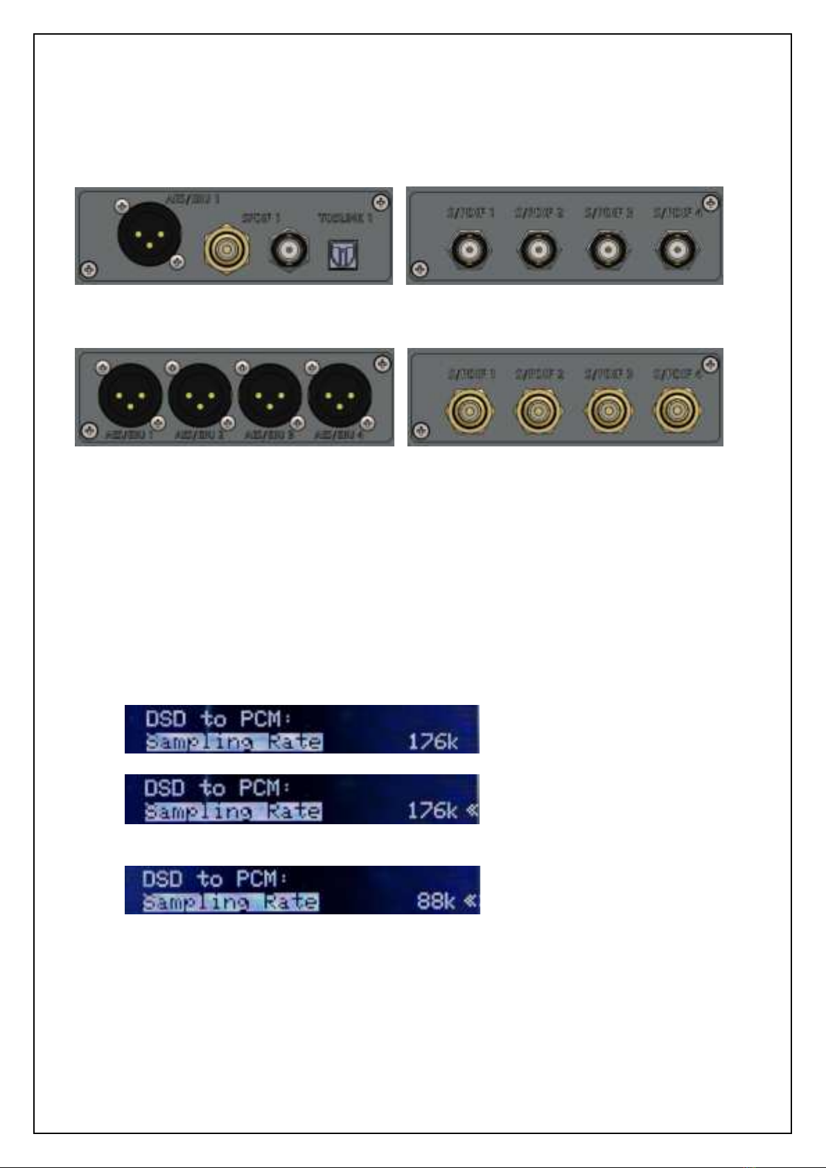
Output Boards
For maximum flexibility, the Vanity
PRO
features an interchangeable output module with
various configurations of the output connectors. There are 4 options in total, covering 1 stereo
and 3 multichannel configurations with RCA, BNC and XLR connectors.
Stereo output Board BNC Multi-channel Output Board
XLR Multi-channel Output Board RCA Multi-channel Output Board
User Interface
The unit is operated using a rotary encoder with a push-button function and an LCD
screen. The navigation is easy through a series of screens with options and metering & diagnostic
data.
•Turing the rotary encoder left and right changes the screen, moves between options in a
configuration menu or selects from multiple options.
•Pushing the knob in one of the two configuration screens will enter the sub-menus.
•Pushing the knob with an item highlighted will enter the item configuration.
•Once the correct option is selected by turning the knob left and right, pushing the knob
again will confirm the selection and return into the menu.
•To exit the menu and go back to the screen selection, long (2 seconds) push of the knob
is required.
•The knob is also used to toggle between stand-by and normal operation of the unit. Long
push the knob to turn the unit on from the stand-by mode. Long push the knob in the
home screen to enter stand-by mode.

Vanity
PRO
–User Manual v1.2
Page 6of 19
Installation
AV Signals
The typical installation of the Vanity
PRO
consists of a HDMI signal source capable of
delivering all compatible digital audio formats and sampling rates, such as a universal player or a
PC and a stereo/multi-channel DAC or audio processor, that can take advantage of the high-
quality and high-resolution S/PDIF or AES/EBU signals. Optionally, the user can connect a HDMI
sink such as a TV or a projector to the HDMI output of the Vanity
PRO
for video pass-through.
The HDMI connectors are quite delicate and should be plugged and unplugged carefully
without excessive force or wiggling to prevent damage. The same applies to the power USB-C
connectors.
Typical signal connections of the Vanity
PRO
Power
The Vanity
PRO
has two independent power inputs. One for the HDMI part, one for the audio
part. The power supplies must meet the voltage and current requirements (see specifications).
5V linear power supply
Power connection of the Vanity
PRO
or
Vanity
PRO
BD/SACD Player
PC with HDMI Audio output
Projector
High Quality DAC
HDMI Out HDMI In
S/PDIF Out

Vanity
PRO
–User Manual v1.2
Page 7of 19
It is strongly recommended to use high quality 5V power supplies, ideally linearly
regulated. Alternatively, multi-port premium and low noise USB chargers can be used. The power
quality directly influences the quality of the output audio signal. Therefore, high quality power
supplies are essential.
Both parts of the unit can be powered independently. The HDMI part is capable of working
on its own without the audio and control part powered up.
Synchronization Clocks
There are two synchronization clock outputs provided on BNC connector with 50Ωoutput
impedance. The purpose of these two clock outputs is to synchronize any downstream audio
devices such as a DAC equipped with a synchronization clock input. The advantage of external
synchronization is usually in better and cleaner clock signal available for the digital to analogue
conversion process compared to a clock recovered from a S/PDIF or AES/EBU stream.
There are “Word Clock” and “Super Clock” signals provided. The Word Clock is a sampling
frequency clock Fs, while the Super Clock is either 22.5792MHz or 24.576MHz.
Theory of Operation
Block diagram
Block Diagram of the Vanity
PRO
showing the main digital audio and control signals
HDMI Extractor
The HDMI interface has combined functionality of a HDMI extractor as well as a repeater.
The main difference between both modes is in handling the EDID data. While in the extractor
mode (default), full audio capabilities in terms of formats (PCM/DSD) and sampling rates are
reported back to the HDMI source, the repeater mode passes through the EDID information from
the connected downstream HDMI sink (TV or projector). The other difference is that in the
extractor mode the audio data are removed from the output HDMI stream and only video part of
the original stream is passed through.
HDMI
Extractor/Repeater
FPGA
MCU
Digital Audio
Output Stage
2x Audio
Oscillator
DAC
Dielectric Barrier
Control
Control
Audio
Clock
Control
Digital
USB
Control

Vanity
PRO
–User Manual v1.2
Page 8of 19
Clock Recovery and Jitter Reduction
To deal with one of the major technical imperfections of the HDMI interface, the Vanity
PRO
uses a pair of low-jitter digitally controlled oscillators and an adaptive control algorithm to lock
onto the incoming audio frequency and output the audio data with perfect timing, completely free
of any jitter or noise of the HDMI interface.
Block diagram of the clock recovery system
Audio data from the HDMI interface is buffered in FIFO memory and clocked out with local
high precision oscillators. As a result, the output signal is completely isolated from the noisy HDMI
domain - interferences from the power supplies, video circuits, etc.
Eye diagram of the output S/PDIF signal. Generic HDMI audio extractor –left, Vanity
PRO
–right.
Effectiveness of the clock recovery system can be seen in the two oscilloscope waveforms
above. There are waveforms with persistence enabled of the output S/PDIF signal –from a generic
HDMI extractor on the left and the Vanity
PRO
on the right. The time base is delayed by 10ms to
show accumulated phase noise using the colour grade. The difference in signal edge timing and
definition can be clearly seen.

Vanity
PRO
–User Manual v1.2
Page 9of 19
DSD Processing Engine
DSD to PCM Conversion
One of the key features of the Vanity
PRO
is the DSD signal processing and conversion to the
PCM format. We have developed a high quality DSD to PCM conversion algorithm to enable owners
of stand-alone DACs to enjoy their favourite SACDs or DSD recordings in the highest quality
possible. The conversion engine has user adjustable characteristics to slightly vary the frequency
roll-off and subsequently the amount of residual ultrasonic noise inherent to the DSD format. The
user can also control the output sample rate and bit depth.
The DSD to PCM conversion algorithm implemented in the Vanity
PRO
sets 0dB SACD level
equivalent to -3dB(FS) PCM level. This approach preserves maximum quality, provides sufficient
headroom for clipping-free signal peaks and over-modulation, and still does not unnecessarily
reduce playback volume in comparison to PCM playback.
DSD and PCM Level Matching
The DSD to PCM conversion produces overall signal level 3dB lower compared to PCM
playback. This is usually not an issue, but thanks to the precision volume control function, the
output levels of DSD and PCM playback can be matched by attenuating PCM signal by 3dB. A
positive side effect is that this helps to create sufficient headroom for inter-sample peaking with
PCM material and DACs that don’t provide such headroom by design.
DoP v1 output mode
The Vanity
PRO
can be also set to output DSD signal in so called DoP format (DSD Over PCM).
This allows the user to send raw DSD material directly to a DoP compatible DAC. More details can
be found here:
http://dsd-guide.com/sites/default/files/white-papers/DoP_openStandard_1v1.pdf
DSD 4.0 Down-Mix
To achieve the best performance during digital DSD playback, it is essential to avoid the
DSD to PCM conversion done by the HDMI source. Universal players can sometimes perform such
task for downmix purposes. For this reason, the widely used 4.0 speaker configuration is covered
by the dedicated down-mix algorithm implemented in the Vanity
PRO
. The algorithm preserves the
overall signal level balance between channels, and it can be described as follows.
FLmix = 0.5FL+0.25C+0.25LFE
FRmix = 0.5FR+0.25C+0.25LFE
SLmix = 0.5SL
SRmix = 0.5SR
To fit the mixed Center and Low-Frequency Effect channels into the front channels, the
overall signal level is shifted by -6dB. No additional signal normalization or scaling is applied.
Since the down-mix processing is carried out with full precision, there is no adverse effect on
sound quality such as reduced dynamics or worse noise figures. The 4.0 downmix can be
performed correctly only with multi-channel 5.1 DSD tracks. If the Vanity
PRO
is connected to a
universal player, the SACD playback priority should be checked or correct setting.
Vanity
PRO
–User Manual v1.2
Page 10 of 19
Volume Control
A part of the processing engine is also full precision volume control. It is used not only for
DSD and PCM level matching, but it also gives the user full control of the overall output level. With
0dB setting (maximum volume) the digital signal path is bit accurate.
All the digital audio processing is performed by a medium sized FPGA. The firmware for
the FPGA is user-upgradeable, together with the main processor firmware, to add new features
and functionality in the future.
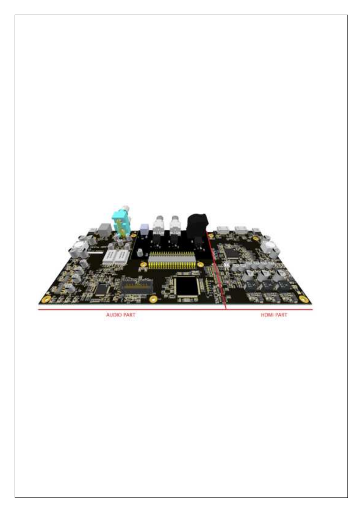
Dielectric Barrier
There is a galvanic barrier put between the HDMI and the audio parts to limit the
electromagnetic noise from the HDMI domain influencing the sensitive audio and clock circuits in
the audio domain. Another advantage of this feature is the option to power the two functional
parts independently from separate power supplies. The audio part can be powered from a high
quality and low noise, possibly linear, power supply without the risk of being plagued by the noise
from the switching regulators on the HDMI side.
Dielectric domains of the Vanity
PRO
shown in the 3D model of the main PCB
Menu system
The menu system is structured into several screens. Some screens are used for monitoring
of the HDMI stream and incoming audio signal properties, while other are used to set the system
and audio processing parameters.

Vanity
PRO
–User Manual v1.2
Page 11 of 19
Home Screen
The home screen provides basic overview of the HDMI link status and digital audio
properties.
MODE: Indicates whether the incoming audio format is PCM
or DSD.
SAMPLING RATE: Indicates incoming sampling rate. Valid
sampling rates are: 44.1, 48, 88.2, 96, 176.4 and 192kHz.
The sampling rate indicator also shows the status of the
clock recovery system. When the algorithm is actively locking
onto the incoming clock rate, the indicator turns orange.
BIT RESOLUTION: Indicates detected bit resolution in the
range between 10 and 24 bits and MUTE when no valid bits
are present. The bit depth detection algorithm monitors the real number of bits used
(continuously changing). It is possible that the detected bit resolution sporadically changes during
playback depending on the actual signal conditions and playback method. This applies primarily
to compressed audio sources.
SIGNAL STATUS: Indicates the status of the incoming audio signal, RUN or STOP.
CHANNELS: Indicates number of valid channels in the range from 2 up to 8.
HDMI IN and HDMI OUT: Indicate whether a HDMI link is established on the input or the output
connector. Red colour indicates no HDMI connection. Green colour indicates established HDMI
link.
Audio Setup
In this screen the user can configure several parameters of the DSD to PCM conversion
algorithm, DSD output mode, 4.0 downmix and output volume.
Sampling Rate: Sets the output sampling rate for DSD to PCM
conversion. The options available are 88.2 and 176.4kHz.
Bit Resolution: Sets the output bit depth for DSD to PCM
conversion. The options available are 16 and 24 bits. The
16-bit option can be useful for owners of so-called non
oversampling (NOS) DACs or older devices designed to
accept 16-bit word length only. In all other cases the 24-bit
options should be selected.
Filter: Sets the DSD to PCM conversion filter characteristics.
There are 4 options available. Sharp HB, Slow HB, Sharp LB and Slow LB. See the following
paragraph for filter details.
PCM Matching: Enables or disables the PCM and DSD output level matching function. With 0dB
setting, PCM is passed through bit accurate without attenuation. With -3dB setting, the PCM
material gets attenuated by 3dB to match the output level from the DSD to PCM converter.
DoP Output: Enables or disables raw DSD output in the DoP format. Use only if your DAC can
accept DoP signal.
DSD 4.0 Downmix: Enables or disables the internal DSD 4.0 downmix function.
Output Volume: Sets the fixed level of the output signal. The range is from 0dB down to -100dB.
Select 0dB for bit accurate signal path with no attenuation.

Vanity
PRO
–User Manual v1.2
Page 12 of 19
Filters Characteristics
There are four conversion filter characteristics available in the Vanity
PRO
. The filters differ
in their steepness and the amount of attenuation of the ultrasonic noise. All four characteristics
can be used when the output sampling rate is set to 176.4kHz and only two with
88.2kHz. The filters optimized for 88.2kHz output sampling rate have “LB”suffix for “Low
Bandwidth”and filters optimized for 176.4kHz output sampling rate have “HB”suffix for “High
Bandwidth”. The frequency plots below show output spectrum of DSD test signal with 1kHz tone
at 0dB converted to PCM 24bit and 176.4kHz. Typical bumps if the DSD noise floor can be
observed in the audio frequency band.
Sharp LB
This filter optimized for 88.2kHz output sample rate has sharp roll-off with cut-off
frequency approximately 20kHz. Chose this filter for high attenuation of the ultrasonic noise.
Slow LB
This filter optimized for 88.2kHz output sample rate has slow roll-off with cut-off
frequency approximately 25kHz. Chose this filter for better transient response with slightly higher
level of the ultrasonic noise.

Vanity
PRO
–User Manual v1.2
Page 13 of 19
Sharp HB
This filter optimized for 176.4kHz output sample rate has sharp roll-off with cut-off
frequency approximately 44kHz. Chose this filter for high bandwidth and high attenuation of the
ultrasonic noise.
Slow HB
This filter optimized for 176.4kHz output sample rate has slow roll-off with cut-off
frequency approximately 55kHz. Chose this filter for the best transient response at the expense
of the highest level of the ultrasonic noise.
There is no general rule for which filter characteristic is the best. The best sounding filter
characteristic should be selected by practical listening and evaluation of sonic qualities for each
specific audio chain configuration. With a very linear audio system with sufficient analogue path
bandwidth the Slow HB filter at 176.4kHz would be expected to be preferred as it maintains the
highest level of DSD bandwidth (including the ultrasonic noise) and the best transient response.
Vanity
PRO
–User Manual v1.2
Page 14 of 19
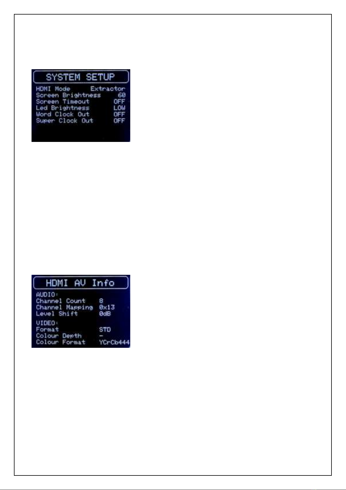
System Setup
The system setup allows the user to configure the screen, stand-by LED, and
synchronization clock outputs.
HDMI Mode: Sets the operation mode of the HDMI interface.
Two options are available: Extractor and Repeater.
The default mode is Extractor, and this setting should be
used for normal operation. In the Repeater mode, the HDMI
stream is passed through as is, including the audio data.
Also, the EDID data are passed through from the HDMI TX
port back to the HDMI source, bypassing the internal EDID.
The Repeater mode should be used only for debugging the
HDMI connectivity as it does not add any functionality over
the default Extractor mode. When the mode is changed the Vanity
PRO
automatically restarts with
the new settings.
Screen Brightness: Sets the screen brightness in the range 0-100. 0 is minimum brightness and
100 is maximum brightness.
LED Brightness: Sets the brightness of the stand-by LED. Three settings are available –Low, Mid
and High.
Word Clock Out: Enables or disables the Word Clock output.
Super Clock Out: Enables or disables the Super Clock output.
HDMI AV Info
In this screen the user can see various parameters of the received HDMI stream as detected
by the HDMI interface. The data is extracted from the HDMI Audio Info Frame as per CEA-861-D.
Channel Count: Indicated number of channels in the “Audio
Channel Count” (CC bits). Value can range from 2 to 8.
Channel Mapping: Indicated number of “Channel
Configuration” (CA bits) in hexadecimal format. Please refer
to CEA-861-D section 6.6 for details.
Level Shift: Indicated value of attenuation as “Level Shift
Value” (LSV bits) converted to dB. Value can range from 0dB
to 15dB.
Format: Indicated current video format. There are three
possible values –STD for Standard, EXT for Extended covering all 4Kx2K resolutions, and 3D
covering all 3D formats.
Colour Depth: Indicated Colour Depth (CD bits). There are five possible values –24, 30, 36 and
48 bits per pixel and “–“ for not indicated.
Colour Format: Indicated Colour Format (Y bits). There are three possible values –RGB,
YCbCr 4:2:2 and YCbCr 4:4:4.
Vanity
PRO
–User Manual v1.2
Page 15 of 19
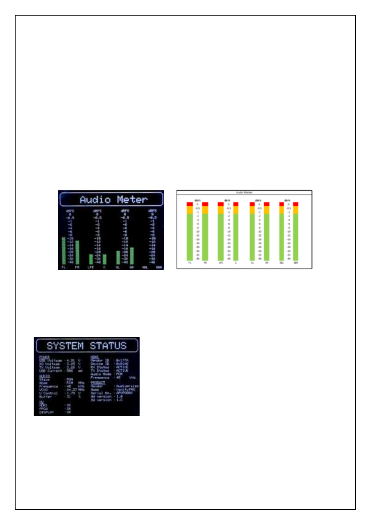
Audio Meters
For quick overview of the audio signals presence and incoming audio signal levels, the
Vanity
PRO
features an 8-channel audio level meter. Each channel has a dedicated meter with the
range from 0dBFS down to -48dBFs and tri-colour grade. The channel names are coded with
standard abbreviations. The additional names in the brackets follow the naming convention of the
CEA-861-D standard.
•FL –Front Left
•FR –Front Right
•C –(Front) Center
•LFE –Low Frequency Effect
•SL –Surround (Rear) Left
•SR –Surround (Rear) Right
•SBL –Surround Back (Rear Center) Left
•SBR –Surround Back (Rear Center) Right
Audio Meters screen and prototype showing the colour-grading of the meters
System Status
This screen shows the overall system status, health, and operational parameters.
POWER: Shows internal voltage measurements of various
voltage rails and Audio side power input current.
AUDIO: Shows various audio parameters which are available
in the home screen as well as oscillator selection, oscillator
control voltage and audio buffer utilization.
HW: Shows internal health checks for the key components –
HDMI interface, FPGA, and the screen.
HDMI: Shows the ID information and status of the HDMI
interface.
PRODUCT: This section shows the product related information, such as serial number, hardware
version and firmware (SW) version. Information from this section should be always provided when
support is required.

Vanity
PRO
–User Manual v1.2
Page 16 of 19
Software Update
The Vanity
PRO
is built on a completely programmable processing and control platform
utilizing a medium size FPGA and a 32-bit processor. New features and functionality can be added
at any time and the firmware can be upgraded by the user through an easy-to-use Windows PC
app.
To update the software, the user must put the unit into firmware update mode and follow
a few simple steps.
•Power off or unplug the power cable of the audio side.
•Pres and hold the encoder knob.
•Apply/connect power to the audio side.
•Wait 2-3 seconds before releasing the knob.
•Connect USB-B cable to the Service port.
•Verify that the unit reports itself in the device manager as “STM Device in DFU Mode”.
If not, please install STM DFU drivers provided.
•Run the Audiopraise Firmware Loader. It requires MS C++ 2013 Redistributable to run.
•Verify the file has been correctly loaded. Select the new firmware file and hit the Upgrade
button.
•Wait for the firmware to load. Once the new firmware has been verified, you can close the
Loader tool and power cycle the unit.
•The Vanity
PRO
now should start with the new firmware. You can verify the firmware
version in the System Status screen.

Vanity
PRO
–User Manual v1.2
Page 17 of 19
Troubleshooting
The Vanity
PRO
implements a robust system of its own health monitoring. The status and
functionality of all major components is continuously monitored and reported in the System Status
screen. Should the user experience any non-standard or unexpected behaviour, diagnosing the
potential issue is easy and straight forward.
Before a fault is suspected, the user should make sure that the unit is correctly installed,
the power, HDMI and digital audio cables are properly connected and secured (BNC connectors).
Also, the HDMI source should be checked for correct operation and configuration. The Vanity
PRO
might not be receiving the expected audio format, sampling frequency or any audio at all due to
incorrect configuration of the HDMI source –universal player, streamer, or computer. With
computers, the HDMI audio support is sometimes restricted or non-existent due to software
drivers. The Vanity
PRO
has been extensively tested with many different Blu-ray and universal
players with positive results. With Windows based PCs, getting the HDMI audio to work sometimes
required trial & error experiments with HDMI audio drivers and settings.
The table below contains a non-exhaustive list of some issues the user might experience,
mainly due to large variability in device configurations the Vanity
PRO
can be used with.
Issue
Possible cause
Solution
HDMI Error reported at start
up.
HDMI part has no power.
Check power connection for
the HDMI part and reboot
the unit.
Audio sampling frequency
indicator remains orange.
HDMI source signal is
unstable or outside of
frequency stability
specifications.
Use different HDMI signal
source.
No audio from downstream
DAC, or DAC unlocked.
SPDIF/AES cable not
connected or audio
sampling frequency too
high.
Check the connections. Set
DSD to PCM sampling
frequency to 88.2kHz
Occasional dropouts in
reproduced audio
DAC with ESS chip might be
too sensitive to frequency
adjustments. See Note 1.
Consult the user manual of
your DAC for DPLL
adjustment.
Note 1
: The user might experience occasional dropouts in the audio signal with a DAC based on a ESS (Sabre) DAC chip.
The jitter attenuation function of this chip called DPLL has several settings and with certain combinations of the DAC’s
local oscillator and the DPLL setting the DAC chip may momentarily unlock when the Vanity
PRO
is adjusting its own audio
clock. Many ESS chip-based DACs have the DPLL settings exposed to the user and using a lower DPLL setting usually fixes
the problem.

Vanity
PRO
–User Manual v1.2
Page 18 of 19
Specifications
HDMI
•Version 2.0a
•1x input and 1x output for pass-through
Digital Audio Outputs
•8 or 2 channel (stereo) output module options
•4xBNC/RCA/XLR for 8-channel output
•1xXLR + 1xBNC + 1xRCA + 1x TOSLINK for 2-channel output
•protocols: S/PDIF (IEC958 / EIAJ CP1201), AES/EBU and TOSLINK
•optional multichannel I2S output module with CMOS 3.3V levels
•transformer isolated outputs
•output impedance: 75Ω for BNC/RCA and 110Ω for XLR
•linear PCM 16/24 bits
•supported sampling rates: 44.1 / 48 / 88.2 / 96 / 176.4 / 192kHz
S/PDIF Re-clocking
•2x custom low jitter on-board VCXO
•digitally controlled frequency tuning, fc<<1Hz
•ultra low-noise power regulators for VCXO and TX circuits
High Quality DSD to PCM Conversion
•custom developed Zero Alias Linear Phase Filter
•37bit arithmetic / 47bit accumulator
•output sample rates: 88.2kHz / 176.4kHz
•4 selectable DSD to LPCM filter characteristics
•full precision 4.0 DSD down-mix option
•DoP v1 output encoding of raw DSD
Full Precision Volume Control
•less than 0.001dB gain error
•bit accurate volume bypass at 0dBFS
•TPDF dithering
•PCM and DSD level matching, outputs PCM and DSD at the same levels
Synchronization outputs
•Word-clock output: BNC, 50Ω impedance, 44.1 / 48 / 88.2 / 96 / 176.4 / 192kHz
•Super-clock output: BNC, 50Ω impedance, 22.5792MHz or 24.576MHz
User Configurable Functionality
•DSD to LPCM output sampling rate: 88.2kHz / 176.4kHz
•DSD to LPCM output bit depth settings: 16 / 24bit
•PCM and DSD output level matching enable / disable
•dedicated DSD 4.0 down-mix enable / disable
•DoP v1 output encoding enable / disable
•4 user-selectable DSD to LPCM filter characteristics
•Adjustable output gain (volume) with 1dB step
HDMI and Audio Monitoring & System Diagnostics
•Monitoring of HDMI stream parameters
•8-channel audio level metering
•Comprehensive system health diagnostics
Power
•separate power for HDMI and audio sides via USB-C connectors
•2x DC input 5V / 1A
Dimensions & Weight
•w/d/h: 266/183/65 mm, including the output connectors
•weight: 1kg

Vanity
PRO
–User Manual v1.2
Page 19 of 19
Revision History
Date
Version
Description
16.10.2021
1.0
Initial release
25.10.2021
1.1
Added Troubleshooting table
18.11.2021
1.2
Added Troubleshooting info related to ESS DACs
Disclaimer
The product has been designed and manufactured using high quality materials in
accordance with best practices in the industry and international harmonized safety standards.
Audiopraise accept no responsibility for any damage or injury caused by incorrect installation, use
or operation of the product.
Table of contents
Popular Scrubber manuals by other brands


PowerPoint
PowerPoint P21561XBSS Installation - use - maintenance

Phaewo
Phaewo PWFMS7 manual

Nobles
Nobles Speed Scrub 3301 Operator and parts manual

PowerPoint
PowerPoint P2152CH Instructions for installation, use and maintenance manual

Tennant
Tennant M17 Series Instruction bulletin

Black & Decker
Black & Decker S500 user manual


