Audiovox Electronics HR7012M User manual

HR7012M / HR7012S
Custom Vehicle Headrests
with 7” Slim Style LED LCD Satellite Monitors
or Built-in
DVD Player for Rear Entertainment
Installation Guide
128-9047
S
HR7012M
SP
HR7012S

Installation of headrest products require careful planning and preparation. Be
extremely careful of seats that have airbags built into them. Keep wiring away from
any air bag wiring (usually identified by yellow connectors and yellow wire jackets).
Damage to air bag wiring can result in personal injury to vehicle occupants. If you
have any questions regarding wire routing or installation in a vehicle, please contact
Audiovox Technical Support at 1-800-225-6074.
When connecting power and ground in a mobile video installation, insure that the
ACC wire is fused at the point where it is connected to the vehicle ACC wiring.
Failure to do so can result in damage to the vehicle if a short circuit develops
between the vehicle connection point and the mobile video product.
IMPORTANT NOTICE
An LCD panel and/or video monitor may be installed in a motor vehicle and visible to
the driver if the LCD panel or video monitor is used for vehicle information, system
control, rear or side observation or navigation. If the LCD panel or video monitor is
used for television reception, video or DVD play, the LCD panel or video monitor
must be installed so that these features will only function when the vehicle is in
“park” or when the vehicle’s parking brake is applied.
An LCD panel or video monitor used for television reception, video or DVD play that
operates when the vehicle is in gear or when the parking is not applied must be
installed to the rear of the driver’s seat where it will not be visible, directly or
indirectly, to be operator of the motor vehicle.
Licensed under one or more of the following patents:
Patent NOS. 7,245,274, 6,899,365, and 6,678,892
2

3
MATERIAL TO USE IN THIS PACKAGE:
1) HR7012 System Monitor (P/N HR7012M/HR7012S) (2 pcs)
Custom Vehicle Headrests with 7” Slim Style LED LCD Satellite Monitors or Built-in DVD
Player for Rear Entertainment
a) Remote Control with
Wireless Game Controller
(P/N 136-5236) - (2pcs)
d) Wireless FMM Interface Box
(P/N 136-5237) - (1pc)
b) 2 Pin DC Power Cable
(P/N 112-3667) - (1pc)
e) Document Kit
c) 12 Pin AV Adapter Cable
(P/N 112-4094) - (1pc)
Note: The HR7012M/HR7012S monitor has
been designed to be interchangeable
from one headrest to the other.
The wireless FMM Interface Box
automatically determines which
headrest is M1 and which headrest is
M2 and sets each headrest to its own
function (IR transmitter channel and IR
receiver remote control codes).
The headrests will still have the Red/Green(MH1 & MH2) and Blue/Yellow (SH1 & Sh2) DIN cables
on them and should be connected to their respective connectors.
2) HR7012PKG Accessories Package (P/N HR7012K) (1 pc)
The Accessories Package contains the following items:
Note: The Document kit is packaged with the
Owner’s Manual (P/N 128-9046) - (1pc),
Installation Guide (P/N 128-9047) - (1pc), and
Product Registration Card (132-6751) - (1pc).
S
HR7012M
SP
HR7012S

2) HR7012GP Game Module Package (P/N HR7012GP) (1 pc) OPTIONAL
The Game Module Package contains the following items:
c)
(P/N 136-5238) - (1pc)
Game Module
RESET SELECT
START
P2
YB
A
X
RESET SELECT
START
P1
YB
A
X
a)
(P/N 136-5239) - (1pc)
Game Controller P1
b)
(P/N 136-5240) - (1pc)
Game Controller P2 d)
(P/N 128-9048) - (1pc)
Game Module Manual
Note: The HR7012GP Game Package is the optional accessories package. For user to upgrade with the
wireless game source feature.
4

5
HR7012 SYSTEM OVERVIEW
1) The HR7012 is a versatile audio / video system with built-in DVD (HR7012M
only) which includes two monitors, that can accept an Audio / Video input and
independent AUX input. A separate audio output is provided for connecting the
FM Modulator to the vehicle's radio.
2) The HR7012M/HR7012S Monitor is comprised of a 7" slime style LED LCD
satellite monitor or with built-in DVD player that allows the user to select from
HR7012M: DVD/USB > M1or M2 > AV > AUX > MEDIA > GAME(optional) /
HR7012S: M1or M2 > AV > AUX > GAME(optional). The HR7012M/HR7012S
monitor has a built-in infrared audio transmitter (CH A)
for use with the optional two-channel wireless headphones (CH A). The
HR7012M/HR7012S monitor also has the ability to select either audio source for
output to the FM Modulator to allow audio playback through the vehicle radio.
3) The HR7012M/HR7012S monitor is comprised of a 7" slime style LED LCD
satellite monitor or with built-in DVD player that allows the user to select from
HR7012M: DVD/USB > M1or M2 > AV > AUX > MEDIA > GAME(optional) /
HR7012S: M1or M2 > AV > AUX > GAME(optional). The HR7012M/HR7012S
monitor has a built-in infrared audio transmitter (CH B) for use with the optional
two channel wireless headphones (CH B).
4) The monitors will show all of the functions with the comprehensive OSD.
5) The optional two-channel wireless Headphone sets have an A-B switch that allow
the users to select the audio from either the HR7012M/HR7012S (CH A) or the
HR7012M/HR7012S (CH B).
6) The optional wired headphone that allow the user to listen audio from the
system.
7) The HR7012M and HR7012S Monitor will accept an audio / video input through
the 1/8” jack located on the front of the unit. The audio / video device could be a
video game system, video camera, or other input device.
8) The optional HR7012GP game package is allow the user to playing the wireless
game from the system.

6
9) Insert/Eject
HR7012M HR7012S
Inner Ring
Insert/Eject Disc
SP
S
AUDIO
R
VIDEO AUDIO
L
AUDIO
R
VIDEO AUDIO
L
PULL UP PULL UP
HR7012M HR7012S
USB
VIDEO
AUDIO L
AUDIO R
WIRED
HEADPHONE
20 degrees

7
VEHICLE PREPARATION
1) Read the manuals and get familiar with the electrical requirements and
connections.
2) Prepare the vehicle by removing any interior trim necessary to gain access to the
vehicle's wiring as well as all areas where interconnecting wire harnesses will be
located. The mounting method and the location will vary from vehicle to vehicle, so
this manual will only focus on the installation of the Master and Satellite Monitors in
the supplied configuration. The best location for the HR7012M/HR7012S System
components are:
a. Monitors: Vehicle-specific Headrest
Note: The Master Monitor should be installed in the passenger position most
used.
b. Wireless FM Interface Box: Under either seat where monitors are located.
3) Locate an accessory power source (+12 VDC should be present when the
ignition key is in the accessory and run positions. 0 VDC should be present
when the ignition key is in the OFF position) and a good ground. Generally,
these wires can be located at the ignition switch or fusebox.
Note: Ensure that the switched power is fused at the source. Failure to do so
may result in vehicle wiring damage.
4) Run the wiring harnesses throughout the vehicle as necessary. (Refer to the
Wiring Diagrams , as well as the wiring instructions for the individual
components and accessory options being installed). Be sure that all the wiring
is protected from sharp edges and is routed in such a manner that it will not be
pinched when it is fully installed. Be sure to leave enough slack in the wiring at
each component to allow sufficient working room. Be sure to leave enough
slack in the monitor cables to allow the headrest to move up or down, and the
seat to move backward and forward.
5) Remove all the components from their packaging and then place them in the
vehicle at their respective locations.
6) Install the Headrests:
a. Remove the vehicle's original Headrests.
b. Hold the Headrest above the seat and insert the two cables into the headrest
support tube holes. Make sure that the headrest is in the correct position
(Display facing the rear).
c. Route the cables through the seat back and out the bottom of the seat.
d. Place the Headrest support tubes into the support tube holes while pulling
the cables to remove the slack. Be sure to leave enough slack in the monitor
cables to allow the headrest to move up or down.

8
7) Connect all the components together (electrically) and verify proper operation of
all the system functions.
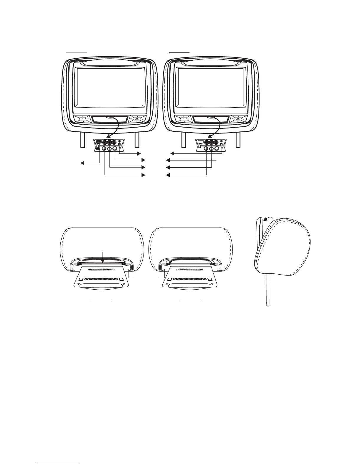
a. The headrest DIN cables and the FMM Interface Box DIN cables are color
coded. Connect each headrest cable to the correct color cable on the FMM
Interface Box.
b. Extend the wireless FM antenna to its full length and orientate for best
reception. Do not place it on the FMM Interface Box or near metal.
c. Connect the DC power jack.
.
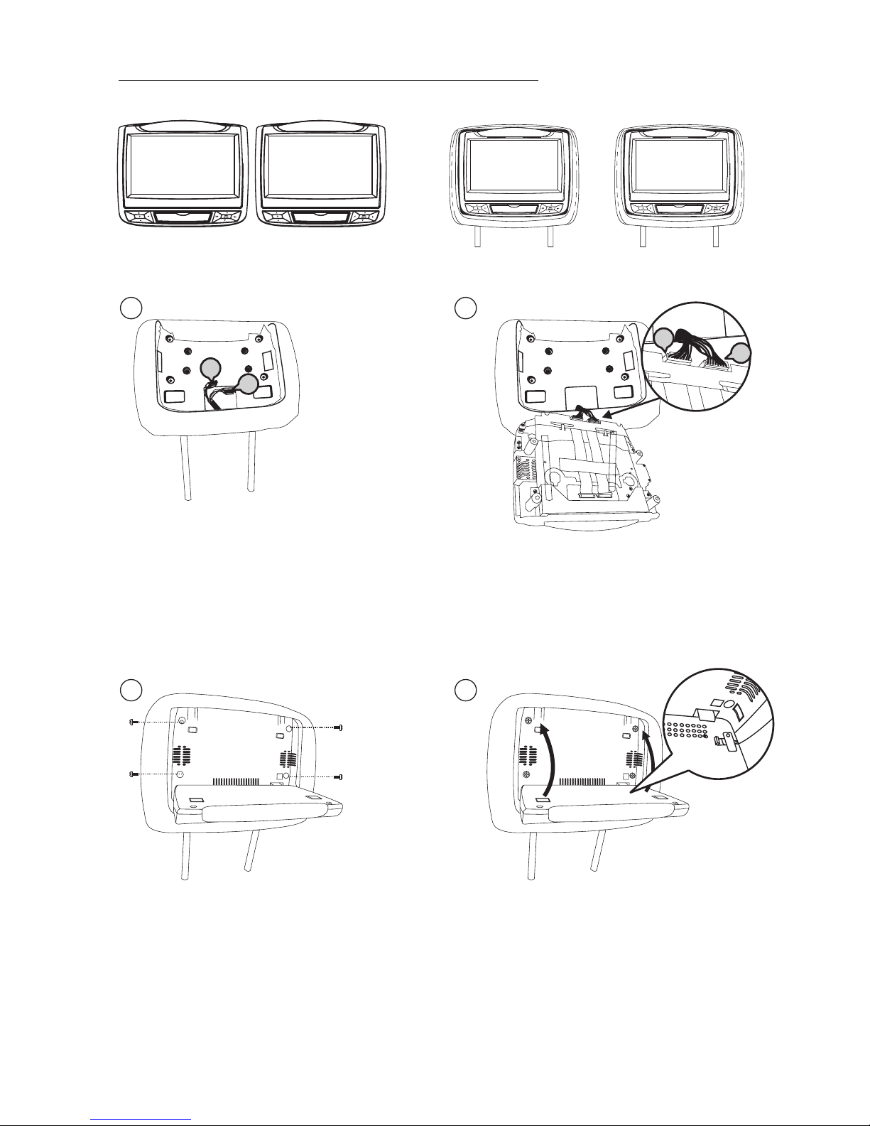
8) After verifying the proper operation of the system, mount each component.
9) When all the components are mounted, recheck the entire system to be sure it is
functioning correctly. Make sure that no wiring was pinched or connected
improperly during the final installation.
Wireless FM Modulator
The HR7011PKG is equipped with a built-in wireless FM Modulator*, that allows
you to listen to the DVD audio signal by tuning your vehicle’s radio to the selected
frequency, (88.1MHz, 88.3MHz, 88.5MHz, 88.7MHz, 88.9MHz, 89.1MHz,
89.3MHz, 89.5MHz, 89.7MHz, 89.9MHZ, 90.1MHz, 90.3MHz, 90.5MHz,
90.7MHz, 90.9MHz, 91.1MHz, 91.3MHz, 91.5MHz, 91.7MHz, 91.9MHz, 92.1MHz,
92.3MHz, 92.5MHz, 92.7MHz, 92.9MHZ, 93.1MHz, 93.3MHz, 93.5MHz,
93.7MHz, 93.9MHz, 94.1MHz, 94.3MHz, 94.5MHz, 94.7MHz, 94.9MHz, 95.1MHz,
95.3MHz, 95.5MHz, 95.7MHz, 95.9MHZ, 96.1MHz, 96.3MHz, 96.5MHz,
96.7MHz, 96.9MHz, 97.1MHz, 97.3MHz, 97.5MHz, 97.7MHz, 97.9MHz, 98.1MHz,
98.3MHz, 98.5MHz, 98.7MHz, 98.9MHZ, 99.1MHz, 99.3MHz, 99.5MHz,
99.7MHz, 99.9MHz, 100.1MHz, 100.3MHz, 100.5MHz, 100.7MHz, 100.9MHz,
101.1MHz, 101.3MHz, 101.5MHz, 101.7MHz, 101.9MHZ, 102.1MHz, 102.3MHz,
102.5MHz, 102.7MHz, 102.9MHz, 103.1MHz, 103.3MHz, 103.5MHz, 103.7MHz,
103.9MHz, 104.1MHz, 104.3MHz, 104.5MHz, 104.7MHz, 104.9MHZ, 105.1MHz,
105.3MHz, 105.5MHz, 105.7MHz, 105.9MHz, 106.1MHz, 106.3MHz, 106.5MHz,
106.7MHz, 106.9MHz, 107.1MHz, 107.3MHz, 107.5MHz, 107.7MHz,107.9MHZ).
This feature is accessed by using the FM transmitter buttons on the remote (FMM
ON/OFF).Whenever the FM Modulator is on, broadcast reception on the vehicle’s
radio will be poor. Switching off the FM Modulator will allow normal radio reception.
*Note: In certain areas where there are a large number of FM radio stations (e.g. large
cities, urban areas), the reception of the FM signal may not be satisfactory, resulting in
static, distorted sound or signal bleed thru from strong local radio stations. This is not a
defect in the product, but the result of a stronger local radio station overpowering the
wireless FM transmitter in your overhead pod.
If wireless reception is unsatisfactory, an optional wired relay box (Audiovox P/N
SIRSWB) can be installed which will improve audio quality. Please contact the installer
if this is the case with your product.

S
SP
S
9
ELECTRONICS INSTALLATION GUIDE
Monitor Unit Install Monitor Unit to Headrest
(HR7012M) (HR7012S)
(HR7012M/
HR7012S - M1)
(
HR7012S - M2)
HR7012M/
12
S
a.) Master/ monitor headrest
cable (MH1/SH1) 8Pin Din Cable.
b.) Master/ monitor headrest
cable (MH2/SH2) 9Pin Din Cable.
Satellite
Satellite
a
b
a.) MH1/SH1
M1 headrest cable
b.) Match MH2/SH2 monitor cable to
M2 headrest cable
Match monitor cable to
a
b
34
With Screw (x4) Move the locking tab to right position
to fully insert the monitor into the
headrest

10
56
Note: Switch off the ACC power during cable and unit installation.
fail to do so may damage to the unit.

11
HR7012M / HR7012S
Master Monitor Satellite Monitor
OPTIONAL
FM ANTENNA
INTERFACE BOX
Relay Box for wireless FM MOD
See antenna note below
SIRSWB
DC
IN
2 PIN DC POWER CABLE
AV Input AV Output
BLUE YELLOW
GREEN RED
HR7012 SYSTEM WIRING DIAGRAM
Relay Box
See the instructions supplied with the SIRSWB for installation.
12 Pin AV Adapter Cable
HR7012GP
OPTIONAL OF HR7012GP (GAME PACKAGE)
S S P
HR7012M / HR7012S
112-4208 112-4209 112-4210 112-4211

128-9047
© 2012 Audiovox Electronics Corp., Hauppauge, NY 11788
This manual suits for next models
1
Table of contents
Other Audiovox Electronics Automobile Accessories manuals