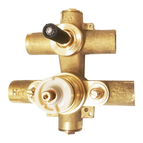
Aura ASR1203-OO User manual

Please read notices on following page
Dimensions of xtures are approximate and may vary ± 6mm (1/4”). Structure measurements must be veried against the unit to ensure proper t.
PRODUCT SPECIFICATIONS ARE SUBJECT TO CHANGE WITHOUT NOTICE.
¾" - 3 Way - No Share - Thermostatic Shower Valve
Installation Manual
Models: ASR1203-OO
Valve Rough-In
Installation Manual

Installation Manual
ASR1203-OO *** Valve Rough-In
Dimensions of xtures are approximate and may vary ± 6mm (1/4”). Structure measurements must be veried against the unit to ensure proper t.
Product images and specications are for illustrative purposes only, product design may vary.
2
GENERAL INSTRUCTIONS
• Read this guide carefully and completely before proceeding.
• It is recommended that you wear safety glasses during the installation.
NOTICE
• For best results, we recommend that a licensed, professional plumber installs this unit.
• Please read over these instructions thoroughly before beginning installation.
• Make sure that you have all tools and supplies needed to complete the installation.
• Please check local building code.
• IF SOLDERING, REMOVE CARTRIDGES TO PREVENT DAMAGE
• Keep receipts (proof of purchase and place of purchase) for this product. The receipt is required should it be necessary to request warranty parts.
MAINTENANCE & CARE FOR YOUR AURA PRODUCTS
• To clean your faucet or accessory, when necessary, wash with a nonabrasive wet soapy cloth. Then wipe dry with a soft towel or cloth.
• Do not use any abrasive chemical or corrosive powders, detergents, window cleaners, disinfectants or any other strong cleaners on your Product
as they will destroy the nish and therefore void the warranty
REMOVAL OF FAUCET
• Always turn the water supply o before removing the existing faucet or disassembling a valve.
• Ensure the water has been turned o.
• Open both faucet handles to release water pressure in lines.
U
p
Ho
t
Cold
6
4
6
4
1
3
Materials and Tools Required
PHILLIPS
SCREWDRIVERS
PENCIL LEVEL WRENCH
THREAD SEALANT ALLEN KEY TUBING CUTTERSOLDER WIREPROPANE TORCH
Materials and Tools Required
Important Measurements

Installation Manual
ASR1203-OO *** Valve Rough-In
Dimensions of xtures are approximate and may vary ± 6mm (1/4”). Structure measurements must be veried against the unit to ensure proper t.
Product images and specications are for illustrative purposes only, product design may vary.
3
Parts List
ITEM DESCRIPTION SKU QTY
1Protective Cover ------ 1
2Screw AP120-200 4
3Valve Box ------ 1
4Hot Water Limiter AP120-204 1
5Handle Extension AP120-201 1
6Diverter Retaining Nut AP120-202 1
7Diverter Cartridge AP120-111 1
8Set Screw AP120-203 1
9Valve Body ------ 1
10 Wall Screw ------ 4
11 Protective Cover ------ 1
12 Retaining Nut AP120-205 1
13 Check Valve AP120-106 2
ITEM DESCRIPTION SKU QTY
14 Thermostatic Cartridge AP120-108 1
15 Plug AP120-102 2
16 ¾" - ½" Connector AP120-112 6
17
18
19
20
21
22
23
24
25
26
9
12
7
6
4
13
3
5
8
2
10
14
11
1
16
15

Installation Manual
ASR1203-OO *** Valve Rough-In
Dimensions of xtures are approximate and may vary ± 6mm (1/4”). Structure measurements must be veried against the unit to ensure proper t.
Product images and specications are for illustrative purposes only, product design may vary.
4
Removing Plastic Covers:
Remove the protective Protective Cover (1) and (2) by
rotating the to the left and pulling outwards.
Open the Stops:
Using a screwdriver, completely open the stops to
maximum opening.
Be sure to not over tighten or loosen the stops as it may
cause the stops to break. (See Figure D1. on the left)
Install Wallboards and Tiles:
After nishing installation of wallboards and tiles, silicone
around valve box. Silicone to create a seal.
Ensure it is silicone where wall and valve box meet.
2A.
2B.
1
2
2A.
2B.
Thermostatic Valve Cover Plate and Handle Installation
HOT
Open
Open
UP
COLD
UP
D1.
CAUTION!
Do not over open when the stops reach
the maximum opening, as it may cause
the stop to malfunction.
Thermostatic Valve Installation
HOT
CH
Open
Open
UP
COLD
UP
1B. 1C.
1D.
1
7
89
10
11
12
2
3
46
51E. (1)
(2)
(3)
(4)
(5)
(6)
(7)
(8)
(9)
(10)
(11)
(12)
Thermostatic Mixer Handle
Cap
Handle set Screw
Volume Control Handle
Plastic Washer
Volume Control Escutcheon
Plastic Washer
Cap
Handle Set Screw
Allen Key
Thermo Escutcheon
Trim
X
X
Diagram 1
ATTENTION!
Please check the thickness, making
sure the plastic surface does not go
beyond the tile surface.
ATTENTION!
REMOVE THE CARTRIDGE BEFORE INSTALLATION.
FLUSH THE HOT AND COLD SUPPLY LINES WITHOUT THE
CARTRIDGE AFTER INSTALLATION. (SEE PAGE 9)
Insert the Valve to the Wall: (EXAMPLE DIAGRAM 1)
Install the valve so that the outside surface of the nished
wall falls between 57.15mm to 69.85mm (2 ¼" to 2 ¾")
from the back of the valve.
Please check the installation to ensure the plastic surface
on the valve does not go beyond the nished tile surface.
Using a level, adjust the two main points to level, then
install the valve.
Connect the Water Pipe:
Attach HOT (Left) and COLD (Right) water supply lines to
the thermostatic valve.
Attach water supply line from the outlet to desired shower
components.
Water Sealing Test:
Close the stops with a screwdriver by rotating the stop.
Open the main water pipe line to test the waterway
sealing. If the sealing on water line leaks, x it then move
on to next step.
Trim/Handle Installation Preparation:
Be sure to check you have these parts before you move
on to the next step.
1A.
1B.
1C.
1D.
1E.

Installation Manual
ASR1203-OO *** Valve Rough-In
Dimensions of xtures are approximate and may vary ± 6mm (1/4”). Structure measurements must be veried against the unit to ensure proper t.
Product images and specications are for illustrative purposes only, product design may vary.
5
1
23
1
2
3
Test the Handle/Valve:
Water temperature will decrease when you rotate
clockwise, and water temperature will increase when you
rotate counter clockwise.
CLEANING STOP FILTERS
Removing the stop lters:
Using a wrench, take out both of the Stops (1) by rotating
them counter-clockwise.
Remove Filter (2) and Valve (3) and check for any debris
or build up.
Use clean water to rinse and clean Filter (2).
Installing the stop lters:
Slide Filter (2) on to Valve (3). Then thread it to the valve
body.
Use a wrench to tighten the Stops (1) to the valve.
3A.
4A.
4B.
Thermostatic Valve Cover Plate and Handle Installation
)
Tempature Lock;
must be pushed.
3A.
4A. 4B.
CAUTION!
If you need to adjust temperature more
than 38°C (100°F), then you need to press
the override button and rotate it counter
clockwise. It should not be possible to turn
the stem further counter-clockwise.
REQUIRED
REQUIRED
Testing Handles and Replacing and Cleaning Stop Filters
CAUTION!
Please check that the marked line on
the thermostatic cartridge points to the
rectangle notch on the plastic parts, if not,
please rotate the brass part. Then install
the handle.
1
2
3
6
9
4
10
511
8
7
1
2C. 2D.
Thermo Cartridge Calibration Area
D2. D3.
Marked Line & Groove
MUST ALIGN
1
2
TOP VIEW
(1)
(2)
Plastic Body
Boarch
Installing Cover Plate:
Carefully install the Trim Plate (1), make sure to keep the
Trim Plate (1) tight against the wall.
Conguring the Cartridge:
Before installing the handle and the rest of the trim,
ensure the thermo cartridge is positioned correctly. Verify
that the line etched on the top of the Plastic Body (1) of
the cartridge lines up exactly with the black line on the
brass Boarch (2) as you are looking down on it.
(See Figures D2. and D3. on the left)
Installing Volume Control Handle:
Install Plastic Washer (4) on diverter. Install the Volume
Control Handle (1). Use the Allen Key (9) to tighten the
Handle Set Screw (3), then insert Set Screw Cap (3).
Installing Thermostatic Handle:
Install Plastic Washer (5) on the thermostatic mixer.
Install the Thermostatic Mixer Handle (6), so that the
safety stop override button is at the 9:00 position. Use
the Allen Key (9) tighten the Handle Set Screw (8), then
insert Set Screw Cap (7).
2C.
2D.
2E.

Installation Manual
ASR1203-OO *** Valve Rough-In
Dimensions of xtures are approximate and may vary ± 6mm (1/4”). Structure measurements must be veried against the unit to ensure proper t.
Product images and specications are for illustrative purposes only, product design may vary.
6
1
2 3 4
5
1
2 3 4
5
REMOVING DIVERTER CARTRIDGE:
Rotate the Volume Control Escutcheon (1) counter
clockwise.
Using a wrench, unscrew the Locking Nut (6) counter
clockwise.
Pull the Thermostatic Cartridge (3) out of the valve.
INSTALLING DIVERTER CARTRIDGE:
Install the Thermostatic Cartridge (3) in to the valve.
Using a wrench, screw on the Diverter Retaining Nut (2)
clockwise.
Rotate Volume Control Escutcheon (4) to the valve
clockwise.
REMOVING THERMOSTATIC CARTRIDGE:
Rotate the Thermo Escutcheon (1) counter clockwise.
Take out the Hot Water Limiter (2).
Using a wrench, unscrew the Retaining Nut (3) counter
clockwise.
Use a Allen key to loosen set Screw (5).
Pull the Thermostatic Cartridge (4) out of the valve.
INSTALLING THERMOSTATIC CARTRIDGE:
Install the Thermostatic Cartridge (4) in to the valve.
Use a Allen key to tighten set Screw (5).
Using a wrench, screw on the Retaining Nut (3)
clockwise.
Put on the Hot Water Limiter (2).
Rotate Thermo Escutcheon (1) to the valve clockwise.
5A.
5B.
6A.
6B.
CAUTION!
Do not over open when the stop
reaches the maximum opening, as it
may cause the stop to malfunction.
REQUIRED
REQUIRED
REQUIRED
REQUIRED
5A.
6A.
5B.
6B.
Removing and Installing Thermostatic Cartridges
Problem Probable Cause Solution
Insucient Water Pressure
Supply Pressure Inadequate
Cartridge May Be Dirty
Showerhead or Handshower Filter Dirty
Check Water Pressure
Clean the Filters (See Page 5)
Clean the Filter
Output Temperature does not Correspond
with Temperature Marked on Handle
Handle not Justied Correctly
Water Heater Set too Low
Adjust the Thermo Handle
Increase the Hot Water Temperature
Safety Stop Button Not Operating Button and/or Spring are Dirty or Worn Clean Spring and Button, Replace if Nec-
essary
Handle is Hard to Turn, Shower or Spout
Dripping Cartridge is Dirty or Worn Out Clean Cartridge, Replace if Necessary
Temperature Regulation Not Possible
Hot and Cold Supplies are Reversed
Thermostatic Cartridge Dirty or Worn
Re-Install the Supply Lines
Replace the Thermostatic Cartridge
Trouble Shooting FAQ

Installation Manual
ASR1203-OO *** Valve Rough-In
Dimensions of xtures are approximate and may vary ± 6mm (1/4”). Structure measurements must be veried against the unit to ensure proper t.
Product images and specications are for illustrative purposes only, product design may vary.
Installation Examples
HOT COLD
HOTC OLD
Open
UP
Open
7
Table of contents
Other Aura Control Unit manuals