Aura LM-270 User manual
Manual
Metal Cutting Band Saw
Model LM-270
F o r y o u r s a f e t y , p l e a s e r e a d t h i s m a n u a l b e f o r e operationcarefully

Motor Power 400V,3~,50Hz,1500/1100W, 4/8pole
Gear rate 25:1
Fly wheel diameter 380 mm
Blade size 3160x27x0.9mm
Blade speed 68 or 34 m/min
O
Saw arm swivel 45 L, , 1 , 0
Coolant pump 400V~, 45W
Packing Size 1770x765x1120 mm
Weight
O O O O O O O
30 L 5 L ,15 R,30 R,45 R,60 R
CONTENT
Specifications 1 Clamping the work piece 8
Safety 2 Adjust cutting angle 9
Safety Instructions For Power Tools 2 Operation cycle 9
Additional Safety Instructions For The Adjusting 11
Metal-cutting Bandsaw 2 Blade tension adjusting 11
Site Considerations 3 Adjusting the blade guide 11
Getting to Know your Metal Cutting Blade guide block 11
BandSaw 4 Changing the blade 11
Unpacking 6 Adjusting the blade to the flywheel 12
Assembly 7 Maintenance 13
Assembling the machine stand 7 Blade choice 14
Assembling the loosen parts and Electrical system 16
accessories 7 Troubleshooting 17
Operation 8 Parts list & diagram 22
Vice adjustment 8
SPECIFICATIONS
1
Max cutting capacity
mm O
45 L
O
45 R O
60 R
270
260
370x220
240
220
240x160
160
150
210
180
180x180
420/490 kg

13. DON’T OVERREACH. Keep proper footing and balance at
SAFETY all times.
14. MAINTAIN TOOLS WITH CARE. Keep tools sharp and
For Your Own Safety Read Instruction clean for best and safest performance. Follow instructions
Manual Before Operating This Equipment for lubricating and changing accessories.
15. DISCONNECT TOOLS before servicing and changing
The purpose of safety symbols is to attract your attention to accessories, such as blades, bits, cutters, and the like.
possible hazardous conditions. This manual uses a series of
symbols and signal words which are intended to convey the 16. REDUCE THE RISK OF UNINTENTIONAL STARTING. Make
level of importance of the safety messages. The progression sure switch is in off position before plugging in.
of symbols is described below. Remember
that safety messages by themselves do not eliminate danger 17. USE RECOMMENDED ACCESSORIES. Consult the owner’s
and are not a substitute for proper accident prevention manual for recommended accessories. The use of improper
measures.accessories may cause risk of injury.
18. CHECK DAMAGED PARTS. Before further use of the tool,
Indicates an imminently hazardous a guard or other part that is damaged should be carefully
situation which, if not avoided, WILL result in checked to determine that it will operate properly and
death or serious injury.perform its intended function.Check for alignment of
moving parts, binding of moving parts, breakage of parts,
Indicates a potentially hazardous situation mounting, and any other conditions that may affect its
which, if not avoided, COULD result in death or operation. A guard or other part that is damaged should
serious injury.be properly repaired or replaced.
Indicates a potentially hazardous situation 19. NEVER LEAVE TOOL RUNNING UNATTENDED. TURN
which, if not avoided, MAY result in minor or POWER OFF. Don’t leave tool until it comes to a
moderate injury. It may also be used to alert complete stop.
against unsafe practices.
This symbol is used to alert the user to
useful information about proper operation of the Additional Safety Instructions For The
equipment.Metal-Cutting Bandsaw
1. Do not operate your bandsaw with dull or badly worn
Safety Instructions For Power Tools
blades. Dull blades require more effort to use and are
difficult to control. Inspect blades before each use.
1. KEEP GUARDS IN PLACE and in working order.
2. Make sure the blade has been properly tensioned and is
2. REMOVE ADJUSTING KEYS AND WRENCHES. Form habit of tracking on the center of the wheels
checking to see that keys and adjusting wrenches are
removed from tool before turning on.3. Always support stock in the vise and make certain it is
firmly secured. Never attempt to hold material by hand
3. KEEP WORK AREA CLEAN. Cluttered areas and benches while sawing.
invite accidents.
4. Keep belt guard and bandsaw wheel covers in place when
4. DON’T USE IN DANGEROUS ENVIRONMENT. Don’t use operating the machine.
power tools in damp or wet locations, or where any
flammable or noxious fumes may exist. Keep work area 5. Never force the saw through the cut. Allow the feed
well lighted.cylinder to control the rate of cutting. If the saw blade
binds or stalls turn the power off immediately.
5. KEEP CHILDREN AND VISITORS AWAY. All children and
visitors should be kept a safe distance from work area.6. Never position fingers or thumbs in line with the cut.
Serious injury could occur.
6. MAKE WORK SHOP CHILD PROOF with padlocks, master
switches, or by removing starter keys.7. Periodically check the horizontal stop screw and the
automatic shutoff limit switch to make sure they are
7. DON’T FORCE TOOL. It will do the job better and safer properly adjusted.
at the rate for which it was designed.
8. Exercise great caution when replacing blades. Wear
8. USE RIGHT TOOL. Don’t force tool or attachment to do a protective gloves and safety glasses when handling the
job for which it was not designed.blade.
9. USE PROPER EXTENSION CORD. Make sure your extension 9. Support long or heavy workpieces which extend from the
cord is in good condition.machine bed with a roller stand or other support device.
10. WEAR PROPER APPAREL. Do not wear loose clothing, 10. Habits-good and bad-are hard to break. Develop good
gloves, neckties, rings,bracelets, or other jewelry which habits in your shop and safety will become second-nature
may get caught in moving parts. Non-slip footwear is to you.
recommended. Wear protective hair covering to contain
long hair.
11. ALWAYS USE SAFETY GLASSES. Also use face or dust
mask if cutting operation is dusty. Everyday eyeglasses Operating this equipment has the potential to propel debris
only have impact resistant lenses, they are NOT safety into the air which can cause eye injury. Always wear
glasses.safety glasses or goggles when operating equipment.
Everyday glasses or reading glasses only have impact
12. SECURE WORK. Use clamps or a vise to hold work when resistant lenses, they are not safety glasses.
practical. It’s safer than using your hand and frees both
hands to operate tool.
2

Like all power tools, there is danger associated with this
Metal Bandsaw. Accidents are frequently caused by lack of
familiarity or failure to pay attention. Use this tool with
respect and caution to lessen the possibility of operator
injury. If normal safety precautions are overlooked or
ignored, serious personal injury may occur.
No list of safety guidelines can be complete. Every shop
environment is different. Always consider safety first, as it
applies to your individual working conditions. Use this and
other machinery with caution and respect. Failure to do so
could result in serious personal injury, damage to
equipment or poor work results.
Site Considerations
Lighting and Outlets
Lighting should be bright enough to eliminate shadow
and prevent eye strain. Electrical circuits should be
dedicated or large enough to handle combined motor
amp loads. Outlets should be located near each machine
so power or extension cords are not obstructing high-
traffic areas. Be sure to observe local electrical codes for
proper installation of new lighting, outlets, or circuits.
Read the manual before assembly and operation.
Become familiar with the machine and its operation
before beginning any work. Serious personal injury may
result if safety or operational information is not
understood or followed.
General Condition
1. Electrical connection: Steady state voltage: 0.9-1.1 of
nominal voltage.
Frequency: 0.99-1.01 of nominal frequency continuously;
0.98-1.02 short time
The mains connection must have maximum16A fuse.
Electrical supply which has protection devices of under-
voltage, over-voltage, over-current as well as a residual
current device (RCD) which maximum residual current rated
at 0.03A.
2. Altitude are not exceeding 1000m.
O
Maximum ambient air temperature is +40 C, minimum
O
ambient air temperature is not less than +5 C.
O
Storage and transportation temperature range is -25 C~
O
+55 C.
The relative humidity does not exceed 50% at a maximum
O
temperature of +40 C, higher relative humidity may be
O
permitted at lower temperature (e.g. 90%@ 20 C).
Floor Load
This machine represents a moderately large weight load in a
small footprint. Most commercial shop floors will be adequate
for the weight of the machine. Some floors may require
additional support. Contact an architect or structural engineer if
you have any question about the ability of your floor to handle
the weight.
To ensure sufficient upright stability of the machine it should be
bolted to floor. For this purpose 4 slots are provided in the
machine's bracket of work stand.
Working Clearances
Working clearances can be thought of as the distances between
machines and obstacles that allow safe operation of every
machine without limitation. Consider existing and anticipated
machine needs, size of material to be processed through each
machine, and space for auxiliary stands and/or work tables. Also
consider the relative position of each machine to one another
for efficient material handling. Be sure to allow yourself
sufficient room to safely run your machines in any foreseeable
operation.
3

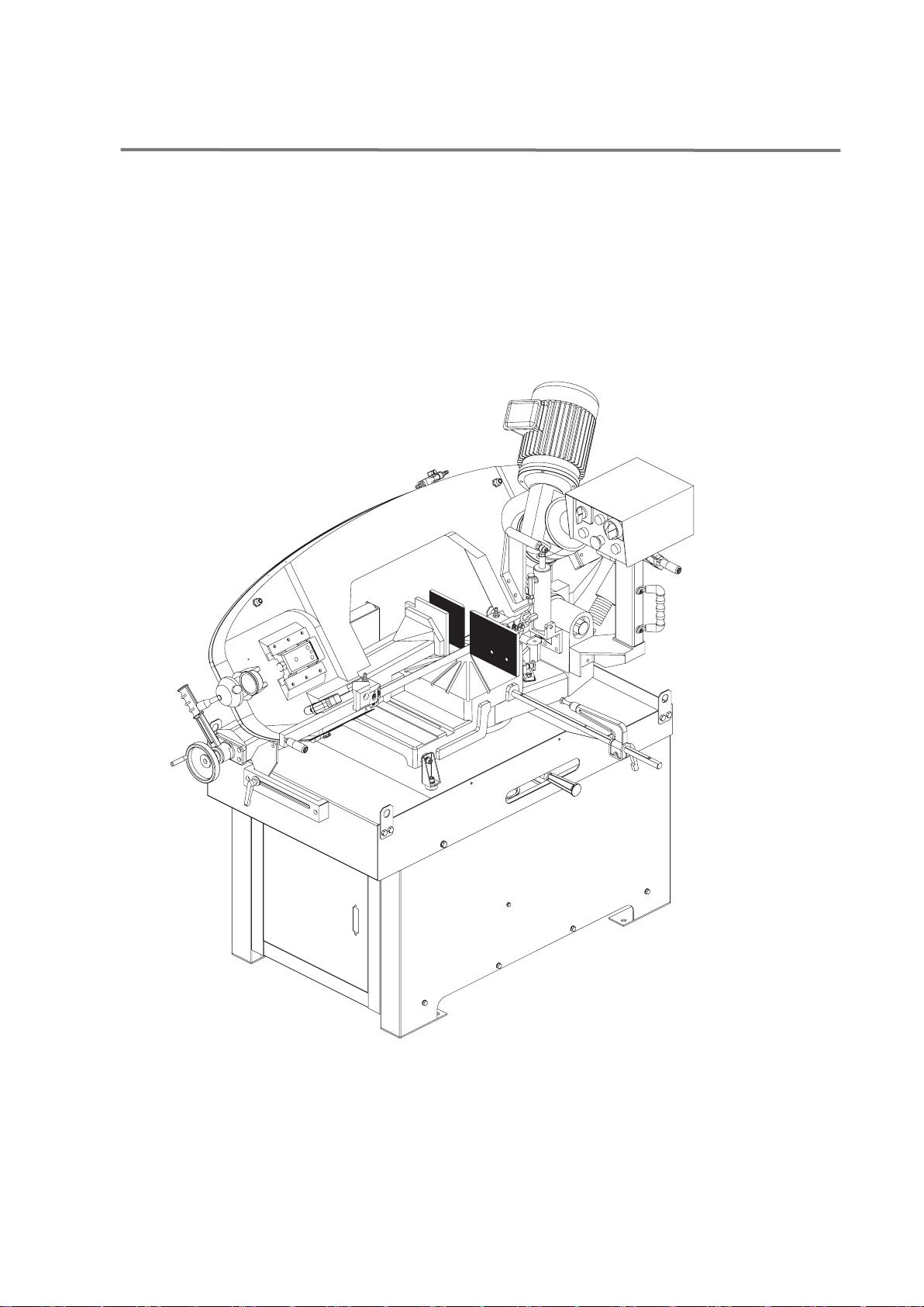
A Saw arm lock lever J Contorl panel----Contains On/Off buttons, Power-
B Vise hand -wheel On indicator light, and the Feed Rate valve.
C Vise quick lock lever K Main motor
D Jaw, vise L Sling plate
E Hydraulic cylinder M Coolant and chip tray
F Saw arm N Bar stop/ work stop
G Blade tension adjusting hand-wheel P Machine stand/ Cabinet stand
H Trigger/ handgrip
GETTING TO KNOW YOUR METAL CUTTING BAND SAW
4

Q Gear box
R Fork, Auto/manual changing
S Saw arm return spring
T Hydraulic flow control valve
W
X
Hydraulic flow regulation valve
Stroke lower position limit switch
Q
R
T
W
X
5

The metal bandsaw is shipped from the factory in a
carefully packed crate. If you find the machine to be All die-cut metal parts have a sharp edge (called “flashing”
damaged, save the containers and all packing materials, ) on them after they are formed. This is generally removed
call your agent.at the factory. Sometimes a bit of flashing might escape
inspection, and the sharp edge may cause cuts or
lacerations when handled, please examine the edges of all
This metal bandsaw is a very heavy machine die-cut metal parts and file or sand the edge to remove the
(400 kgs. shipping weight). DO NOT over-
flashing before handling.
exert yourself while unpacking or moving
your machine--get assistance. In the event
that your machine must be moved up or
down a flight of stairs, be sure that the
stairs are capable of supporting the
combined weight of people and the machine.
Serious personal injury may occur.
When you are completely satisfied with the condition
of your shipment, you should inventory its parts.
Piece inventory
Main saw unit
6- Hex head screw M10x20
6- Washer 10mm
Bar stop/work stop
2.5,3,4,6,10 mm allen wrench(5)
10-13 duo-open wrench
17-19 duo-open wrench
Machine stand parts
Right part
Left part
Bottom plate
Door frame w/door
Shelf( V & H)
16-Hex head screw M8x16
20-Washer 8mm
4-Hex nut M8
5-Hex head screw M6x12
5-Hex nut M6
10-Washer 6mm
Clean Up
The unpainted surfaces are coated with a waxy oil to
protect them from corrosion during shipment. Remove this
protective coating with a solvent cleaner or citrus-based
degreaser. Avoid chlorine--based solvents as they may
damage painted surfaces should they come in contact.
Always follow the usage instructions on the product you
choose for clean up.
Many of the solvents commonly used to clean machinery
can be highly flammable, and toxic when inhaled or
ingested. Always work in well--ventilated areas far from
potential ignition sources when dealing with solvents. Use
care when disposing of waste rags and towels to be sure
they do not create fire or environmental hazards. Keep
children and animals safely away when cleaning and
assembling this machine.
Do not use gasoline or other petroleum-based solvents to
remove this protective coating. These products generally
have low flash points which makes them extremely
flammable. A risk of explosion and burning exists if these
products are used. Serious personal injury may occur.
UNPACKING
6

ASSEMBLY
This metal cutting bandsaw is completely assembled, just
needs to assemble the machine stand.
Assembling the machine stand
Join the left part, right part to bottom plate with 6-hex
head screws M8x16 w/6- 8mm washers.
Attach the H-shelf to assembled parts with 4--hex head
screws M8x16 w/4- 8mm washers.
Attach the V-shelf to assembled parts with 5--hex head
screws M6x12 w/10- 6mm washers, 5-hex nuts M6.
Attach the door frame w/door and fasten it with 4-hex
head screws M8x16 w/8-8mm washer, 4-hex nuts M8.
Mount the Coolant system assembly to bottom plate
with 2-Hex head screws M8x16 w/2-8mm washer.
Assemble the loose parts and accessories
Fit the components supplied:
Mount bar stop rod.
Mount and align the roll-supporting arm as per the
counter-vice table.
Dis activation of machine
Carefully lift the saw head onto base, and fasten the If the machine is to be out of use for a long period, it is
machine head by 6-Hex head screw M10x20, and washer advisable to proceed as follows:
10mm.
Detach the plug from the electric supply panel,
Loosen blade,
Release the saw arm return spring,
Lowing the saw arm as possible,
Empty the coolant tank,
Carefully clean and grease the machine,
If necessary, cover the machine.
lCheck the condition and suitability of the equipment
available.
lDo not touch the suspended loads and remain at a
safe distance from them.
Before starting to lift the machine make sure that all
movable parts have been securely fastened.
Ensure that the crane's lifting capacity is suitable for the
machine. Lift the machine carefully and move it slowly,
avoiding bumps or sudden movements.
lThe lifting and transporting operations can be
extremely dangerous if not carried out with maximum
caution.
lMove all unqualified personnel away from the area.
Clean, clear and close off the installation area.
Fig 1
7
Fig 2

OPERATION
The machine has been designed to cut metal building
materials, with different shapes and profiles, used in
workshops, turner’s shops and general mechanical
structural work.
Only one operator is needed to use the machine, that
must stand on the front of machine as shown in the
picture.
Before starting each cutting operation, ensure that
the part is firmly clamped in the vice and that end is
suitably supported.
Do not use blades of a different size from those stated
in machine specifications.
If the blade gets stuck in the cut, release the running
button immediately, switch off the machine, open the
vice slowly, remove the part and check that the blade
or its teeth are not broken. If they are broken, change
the tool.
Clamping the work piece
Place work piece between the jaws.
Use the hand wheel to approach the vice jaw to the
work piece, leaving 3-4mm of space. Lock down work
piece by lowering the quick lock lever(4).
When the cutting cycle is finished, release vice by
raising the quick lock lever (4). Upon releasing the
quick lock lever (4), the vice jaw will open to the same
distance that was set initially. This allows for rapid
loading of same size material.
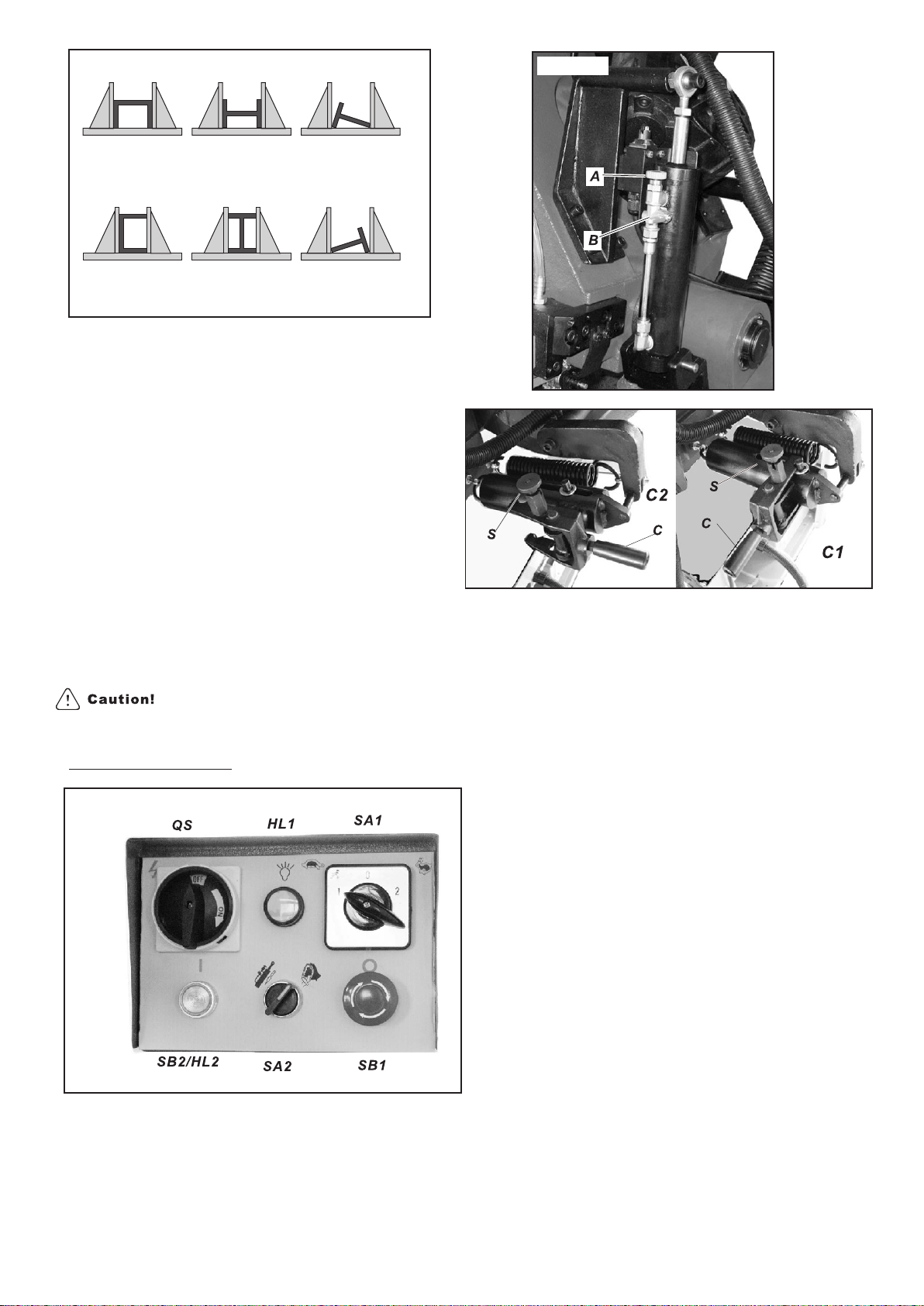
These figures below examples of suitable clamping of
different section bars, bearing in mind the cutting
capacities of the machine in order to achieve a good
efficiency and blade durability.
Once in position, move the lever(2) to the right to
lock it into position. If the lever (2) is not between the
vise/bed mounts and facing the user, then the vise will
not be able to lock. If the vise lever(2) has gone
beyond or is obstructed by a vise/bed mount, then use
the following procedures.
Adjust the lever(2) by grasping at the pivot point(P)
and lowering it, which may assist in the adjustment.
The lever can now be freely rotated into a more
convenient position. Some movement of the vise
Vice adjustment jaw may be required. Raise the lever (2) then move to
the right to lock.
The device does not require any particular adjustment;
in case of excess play of the sliding guide, tighten Lock the track support(1) by turning handle clockwise.
slide screw more.
To move the vise in either direction, the vise jaw must
be unlocked at two points.
Release the track support by turning the handle(1)
counter-clockwise.
Release the vise by moving the lever(2) to the left.
The vise (5) may now be moved to right position (7) or
left position (6)by pushing it with one hand on the vise
and the other hand on the track handle(1).
Fig 3
8
Fig 4
Fig 5
Fig 6
Adjust cutting angle
Operation cycle
Before operation, all the main organs of machine must
be set in optimum conditions.
Auto cutting operation
Using the right side, angles can be cut up to 60
degrees. This requires that vise jaw to be set on
the left side(6, fig6). Use the procedures for Vise
Adjustment, to place it in left side position.
Using the left side, angles can be cut up to 45
degrees. This requires the vise jaw to be set on the
right side(7,fig6). Use the procedures for Vise
Adjustment, to place it in right side position.
Unlock lever (3,fig4) and use the handle under the
control box to rotate the saw frame arm until you
reach mechanical stop and check if the index
corresponds to desired degrees; if not , operate on
Move the handle to the auto position (C2,fig10).Lift
the set screws to make measures meet.
the spring knob (S) and secure its pin into its slot.
Use manual/auto selector(SA2 fig8) to select auto.
Select c u tting speed by turning speed
selector(SA1 fig8).Turtle is low speed, rabbit is high
speed, and ‘O’ is neutral.
Turn main connect switch (QS fig8) to the ON
position.
Check that the indicator light (HL1) is on.
Load work piece and clamp it properly.
Press start/reset button(SB2) to start machine.
Check that the blade is running in the correct
direction.
Slightly pull the saw arm down to get rid of air
bubbles from the hydraulic cylinder.
Adjust hydraulic flow control valve(A) by slightly
turning the valve counter-clockwise to let saw arm
descend and start cutting.
Press the emergency push button ( K fig 11 or SB1
fig8) down to shut off all functions. To release the
emergency shut off rotate emergency push button (K
or SB1) clock-wise. The button will pop up and then
the cutting cycle can be restarted.
Close the hydraulic flow control valve(A) by turning
the valve clockwise all the way to the end.In general, start cuts by slightly turning hydraulic
flow control valve(A) counter-clockwise from 2 to 3
Raise the saw arm. to control the saw arm descent rate. If the arm
descends too quickly, turn hydraulic flow regulation
Lift the spring knob (S) to release the pin from its slot. valve (B) counter-clockwise all the way back to stop
This will free the fork handle( C). its descent.
9
Fig 7
Fig 8
Fig 9
Fig 10

Fully open the hydraulic flow control valve(A) by
turning the valve counter-clockwise all the way to the
end.
Press trigger switch(J) to start operation.
If cutting pipe with thin walls, reduce the saw arm
descent rate by adjusting the flow control valve(A).
Press the emergency push button(K fig11,or SB1 fig8)
down to shut off all functions.
To release the emergency push button(K fig11, SB1
fig8) rotate the mushroom shaped button clock-wise.
The button will pop up and then the cutting cycle can
be restarted.
A saw arm dropping too quickly can cause the blade
to stall on the work pieces and the machine will shut
off. Push down the emergency push button (K or SB1)
to immediately stop all machine functions.
Lift the spring knob (S) to release the pin from its slot.
This will free the fork handle(C).Move the handle to
the manual position (C1,fig10). Lift the spring
knob(S) and secure its pin into its slot.
Use manual/auto selector(SA2) to select handle
icon.
Select cutting speed by turning speed selector(SA1).
Turtle is low speed, rabbit is high speed, and ‘O’ is
neutral.
Turn main connect switch(QS) to the ON position.
Check that the indicator light(HL1) is on.
Load work piece and clamp it properly.
Fully open the hydraulic flow regulation valve(B) by
turning the valve clockwise all the way to the end.
Trigger switch (manual cutting) operation
Full close the hydraulic flow control valve(A) by
turning the valve clockwise all the way to the end.
Raise the saw arm as possible.
Fig 11
Fig 12
J
10

ADJUSTING
In case the blade needs to be replaced, make sure to
always install 0.9mm thick blades for which the the
blades guide pads have been adjusted.
In the case of toothed blade with different thickness
adjustment should be carried out as follows:
Loosen allen screw (L), adjusting the set screw (M),
the movable teeth (Q) will far away or close to the
blade.
Make sure that between blade and two side teeth
there is 0.05mm of play.
Then re-tighten allen screw (L).
Make sure that between blade and upper teeth of the
pad this is at least 0.2~0.3 mm of play; if necessary,
loosen the allen screws(P) that fasten the block and
adjust accordingly.
Changing the blade
Before performing the following operations , the
electric power supply and the power cable must be
completely dis-connected.
Lift the saw arm.
Loosen the blade with the hand-wheel, slide the
mobile blade guide to far away as possible, remove
the blade guard lock knob, remove the blade guard
and remove the old blade, from the flywheel and the
blade guide block.
Assemble a new blade by placing it first between the
pads and then on the race of flywheels, paying
particular attention to the cutting direction of the
teeth.
Tension the blade and make sure it perfectly fits
inside the seat of the flywheels.
Assemble the blade guard, and fasten it with relative
knobs.
Check the safety microswitch is activated othewise
when electric connection will be restored the machine
will not start.
Blade guide block
The blade is guided by means of adjustable pads set
place during inspection as per the thickness of the
blade with minimum play as shown in the figure.
Blade tension adjusting
The ideal tension of the blade is achieved rotating the
hand wheel until it touches the micro switch, that
actuates the operation of the machine is actuated.
The position of this switch is factory set during
inspection, after having tightened the blade on
the lengthening values indicated by its
manufacturer as per specific dimensions set with
the help of a special instrument. When replacing
the blade, if the thickness and the width differ, it
will be necessary to correct the projection of the
switch. For this purpose we suggest to strictly select
blades having the same features as mounted
originally.
Proper blade tension is 12 to14 MPa as measured on
a blade tension gauge.
Adjusting the blade guide
Disconnect the machine from the power source.
Use a Allen wrench to loosen allen screw (A) on the
square lock plate.
Hold the handle(B) and slide blade guide block as
close as possible to the material without interfering
with the cut.
Tighten the allen screw(A).
Reconnect the machine to power source.
Fig 13
Fig 14
Fig 15
11

12
Always assemble blades having dimensions
specified in this manual and for which the blade
guide heads have been set.
This metal cutting bandsaw can not accept thick
than 0.9mm blade.
Adjusting the blade to the flywheel
Loosen the hex screws (Q1,Q2,Q3).
Use an allen wrench on set screw ( R) to adjust the tilt
of the flywheel.
Turning the set screw clockwise will tilt flywheel so
that the blade will ride closer to the flange.
Turning the set screw counter-clockwise will tilt
flywheel so that the blade will ride away from the
flange.
After the adjustment is finished fasten the hex
screw in this order: Q3, Q2, Q1.
Checking the adjustment of the blade
Use a strip of scrap paper and slide it between the
blade and the flywheel while it is running.
if the paper is cut then the blade is riding too close to
the flange. Re-adjust.
if you notice that the blade is riding away from the
flange.Then re-adjust.
Always assemble blades having dimensions
specified in this manual and for which the blade
guide heads have been set.
Fig 18
Fig 16
Fig 17
Fig 19

The gear box
MAINTENANCE
The maintenance jobs are listed below, divided into
Daily, Weekly, Monthly and 6-monthly intervals. If the
following operations are englected, the result will be
premature wear of the machine and poor performance.
Daily maintenance
General cleaning of the machine to remove
accumulated shavings.
Clean the lubricating coolant drain hole to avoid excess
fluid.
Top off the level of lubricating coolant.
Check blade for wear.
Rise of saw frame to top position and partial slacking of
the blade to avoid useless yield stress.
Check functionality of the shields and emergency
stops.
Weekly maintenance
Thorough cleaning of the machine to remove shavings,
especially from the lubricant fluid tank.
Removal of pump from its housing, cleaning of the
suction filter and suction zone.
Use compressed air to clean the blade guides (guide
bearing and drain hole of lubricating cooling).
Cleaning flywheel housing and blade sliding surface on
flywheels.
Monthly maintenance
Check the tightening of the motor flywheels screws.
Check that the blade guide bearings on the heads are
perfect running condition.
Special maintenance
Check the tightening of screws of the gear motor, pump,
Special maintenance must be conducted by skilled
and accident protection guarding.
personal. We Advise contacting your nearest dealer
and/or importer. Also the reset of protective and safety
6-monthly maintenance
equipment and devices ( of the reducer), the motor, the
motor pump, and other electrical components requires
Continuity test of the equipotential protection circuit.
special maintenance.
Maintenance of other machine parts
The worm drive gearbox mounted on the machine is
maintenance-free guaranteed by its manufacture.
Oils for lubricating coolant
Considering the vast range of products on the market,
the user can choose the one most suited to their own
requirements, using as reference the type SHELL
LUTEM OIL ECO. THE MINIMUM PERCENTAGE OF
OIL DILUTED IN WATER IS 8-10%.
The gear box requires periodic changing of oil. The oil
must be changed by the first 6 months of a new
machine and every year thereafter.
To change the gear box oil
Disconnect the machine from the power source.
Raise the saw arm to vertical position.
B
Replace the screw after oil completely flows off.
Place the saw arm back to horizontal position.
Fill Gear box with approximately 0.6 liter of gear oil
through the hole of the vent screw ( ).
For reference, use SHELL type gear oil or Mobile
gear oil #90.
13
Fig 20
B
Draw off gear oil by loosening the allen head screw ( A )
A

14
BLADE CHOICE
Structure” is for reference only.)
4. In the applicable row, read across to the right and find
the box where the row and column intersect. Listed in
Selecting the right blade for the job depends on a variety the box is the minimum TPI recommended for the
of factors, such as the type of material being cut, variable tooth pitch blades.
hardness of the material, material shape machine
capability, and operator technique. 5. The "Cutting Speed Rate Recommendation" section of
the charts offers guidelines for various metals, given in
The chart below is a basic starting point for choosing feet per minute (speed FPM) and meters per minute in
blade type based on teeth per inch (TPI) for variable parenthesis. Choose the speed closest to the number
tooth pitch blades and for standard raker type bi-metal shown in the chart.
blades/HSS blades. However, for exact specifications of
bandsaw blades, contact the blade manufacturer. (The next page”Blade
To select the correct blade TPI:
1. Measure the material thickness. This measurement is
the length of cut taken from where the tooth enters the
workpiece, sweeps through, and exits the workpiece.
2. Refer to the "Material Width/Diameter" row of the
blade selection chart and read across to find your
workpiece thickness you need to cut.
3. Refer to the "Material Shapes" row and find the shape
and material to be cut.
196~354
(60) (108)
196~354
(60) (108)
180~220
(54) (67)
180~220
(54) (67)
220~534
(67) (163)
229~482
(70) (147)
150~203
(46) (62)
108~225
(33) (75)
65~85
(20) (26)
321
(98)
220
(67)
203-413
(62) (65)
95-213
(29) (65)
75-118
(25) (36)
203
(62)
229~482
(70) (147)
220~534
(67) (163)
180~220
(54) (67)
180~220
(54) (67)
203
(62)
15
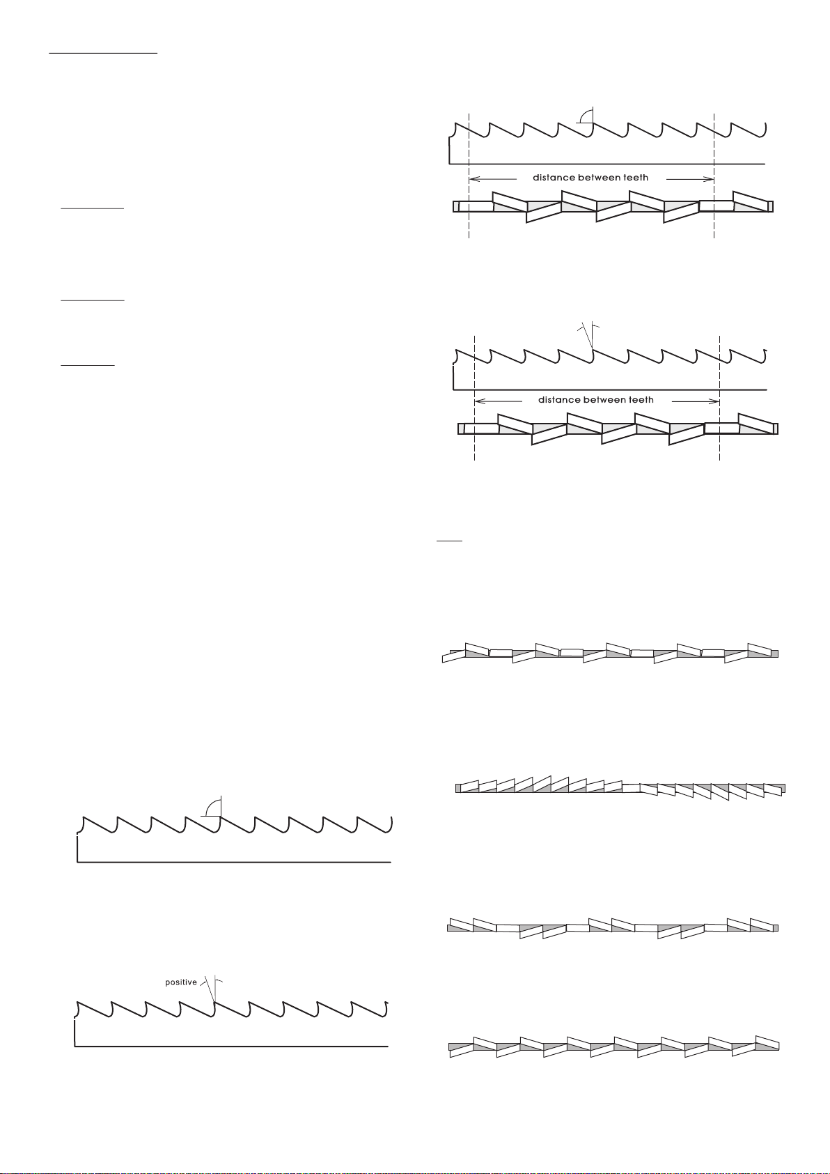
Blade Structure COMBO TOOTH
Pitch varies between teeth and consequently varying teeth
size and varying gullet depths. Pitch varies between teeth,
Bi-metal blade are the most commonly used. They consist of which ensures a smoother, quieter cut and longer blade life
silicon-steel blade backing by a laser welded high speed steel owing to the lack of vibration.
(HSS) cutting edge. The type of stock are classified in M2, M42,
M51 and differ from each other because their major hardness
due to increasing percentage of Cobalt (Cc) and molybdenum
(Mo) contained in metal alloy.
There are several key factors to consider in choosing a blade:
Tooth Pitch---The number of teeth per inch (TPI) on the
blade, also known as tooth pitch. Select a pitch
which will assure that at least three teeth are
contacting the workpiece while cutting. This helps to Another advantage offered in the use of this type of blade in
distribute the cutting forces and avoids tooth the fact that with an only blade it is possible to cut a wide
breakage.range of different material in size and type.
Tooth Form---There are four common forms of teeth on the COMBO TOOTH
blade: buttress, claw-tooth, precision and tungsten O O
9 -10 positive rake
carbide. Precision is the most common and is the
type supplied with this saw.
Tooth Set---Set is the degree to which the teeth are bent
away from the blade. Typical tooth set styles are
raker, wave and straight set.
Always select and use good-quality saw blades and choose
the right blade for the job. Discuss your cutting
requirements with your saw blade dealer to make sure you
are getting the type of blade which best suits your need.
Poor quality blades and improper use are often the cause This type of blade is the most suitable for the cutting of
of premature blade failure.section bars and large and thick pipes as well as for the
cutting of solid bars at maximum machine capacity. Available
Many conditions can lead to breakage. Blade breakage is, in pitches: 3-4/4-6.
some cases, unavoidable, since it is the natural result of the
peculiar stresses that bandsaw blades are subjected to. Sets
Blade breakage is also due to avoidable causes.
Saw teeth bent out the plane of saw body, resulting in a wide
Avoidable breakage is most often the result of poor care cut in the work-piece.
or judgement on the part of the operator when mounting or
adjusting the blade or support guides. The most common Regular or Raker Set
causes of blade breakage are:Cutting teeth right and left, alternated by a straight
tooth.
(1) faulty alignment and adjustment of the guides;
(2) insufficient number of teeth contacting the cut;
(3) feeding too fast;
(4) tooth dullness or absence of sufficient set;
Of great use for materials with dimensions superior to 5mm.
(5) excessive tension;
Used for cutting of steel, castings and hard nonferrous
(6) using a blade with a lumpy or improperly finished
materials.
weld;and
(7) continuously running the bandsaw when not in use.
Wavy Set
REGULAR TOOTH Set in smooth waves.
O
0 rake and constant pitch
This set is associated with very fine teeth and it is mainly
used for cutting of pipes and thin section bars (from 1-3mm).
Most common form for transversal or inclined of solid small and Alternate Set (in groups)
average cross-sections or pipes, in laminated mild steel and Groups of cutting teeth right and left, alternated by a
gray iron or general metal. straight tooth.
POSITIVE RAKE TOOTH
O O
9 -10 positive rake and constant pitch This set is associated with very fine teeth and it is used for
extremely thin materials (less than 1mm).
Alternate Set( individual teeth)
Cutting teeth right and left.
Particular use for crosswise or inclined cuts in solid sections or
large pipes, but above all harder materials (highly alloyed and This set is used for the cutting of nonferrous soft materials,
stainless steels, special bronze and forge pig iron). plastics and wood.
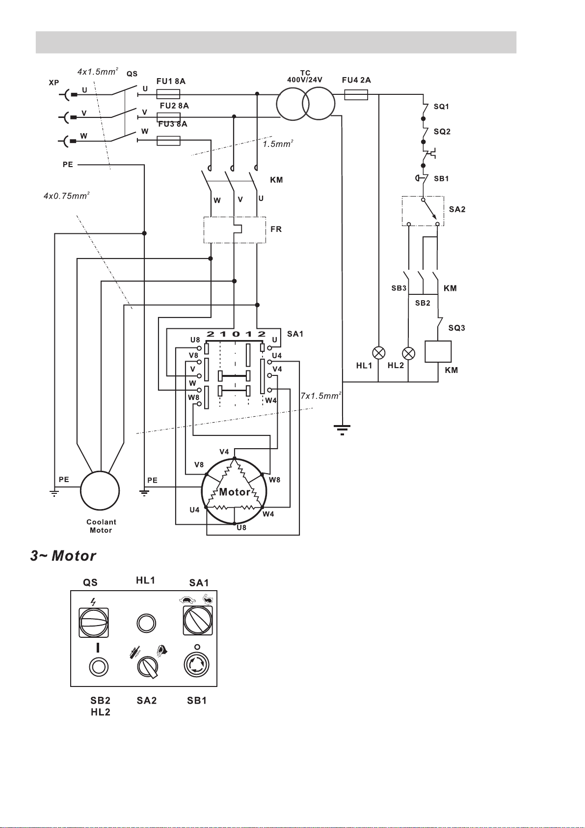
ELECTRICAL SYSTEM
QS:Main Switch
SA1: Hi/Low Speed Control
SA2: Mode Switch
KM:Contactor
FR: Thermal protector
TC: Transformer
FU1-3: Fuse 8A
FU4:Transformer Fuse 2A
HL1:Power Light
HL2:Run Light
SB1: Emergency Stop Button
SB2: ON Button
SB3:Button on Grip-hand
SQ1-3: Limit Switch
16

TROUBLESHOOTING
This chapter lists the probable faults and malfunctions that could occur while the machine is being used and suggests possible
remedies for solving them.
The first paragraph provides diagnosis for TOOL and CUTS, the second for ELECTRICAL COMPONENTS.
FAULT
Tooth Breakage
PROBABLE CAUSE
Too fast advance
Wrong cutting speed
Wrong tooth pitch
Chips sticking onto teeth and in the
gullets or material that gums
Defects on the material or material too
hard
Ineffective gripping of the part in the vise
The blade gets stuck in the material
Starting cut on sharp or irregular section
bars
Poor quality blades
Previously broken tooth left in cut
Cutting resumed on a groove made
previously
Vibrations
Wrong tooth pitch or shapes
insufficient lubricating, refrigerant, or
wrong emulsion
REMEDY
Decrease advance exerting less cutting pressure.
Adjust the braking device.
Change speed and /or type of blade .See chapter
on “Material classification and blade selection”, in
the section Blade selection table according to
cutting and feed speed.
Choose a suitable blade. See Chapter “Material
classification and blade selection”.
Check for clogging of coolant drain holes on the
blade-guide blocks and that flow is plentiful in
order to facilitate the removal of chips from the
blade.
Material surface can be oxidized or covered with
impurities making them, at the beginning of the
cut , harder that the bade itself , or have harder
areas or inclusions inside the section due
productive agents used as casting sand, welding
wastes, etc. Avoid cutting these materials or in
a situation a cut has to be made use extreme care,
cleaning and remove any such impurities as
quickly as possible.
Check the gripping of the part.
Reduce feed and exert less cutting pressure.
Pay more attention when you start cutting.
Use a superior quality blade.
Accurately remove all the parts left in.
Make the cut elsewhere, turning the part.
Check gripping of the part.
Replace blade with a more suitable one. See
“Material classification and blade selection” in
the Blade Types selection. Adjust bade guide
pads.
Check level of liquid in the tank. Increase the flow
of lubricating refrigerant, checking that the hole
and the liquid outlet pipe are not blocked .Check
the emulsion percentage.
17

FAULT
Premature Blade Wear
Blade Breakage
PROBABLE CAUSE
Faulty running-in of blade
Teeth positioned in the direction opposite
the cutting direction
Poor quality blade
Too fast advance
Wrong cutting speed
Defects on the material or material too
hard
insufficient lubricating refrigerant or
wrong emulsion
Faulty welding of blade
Too fast advance
wrong cutting speed
Wrong tooth pitch
Ineffective gripping of the part in the vice
Blade touching material at beginning of
cut
Remedy
REMEDY
See “Material classification and blade selection”
in the Blade running –in section.
Turn teeth in correct direction.
Use a superior quality blade.
Decrease advance, exerting less cutting pressure.
Adjust the braking device.
Change speed and /or type of blade. See chapter
on “Material classification and blade selection”,
in the section Blade selection table according to
cutting and feed speed.
Material surface can be oxidized or covered with
impurities making them, at the beginning of the
cut, harder the blade itself , or have hardened
area or inclusion inside the section due to
productive agents used such as casting sand,
welding wastes, etc. Avoid cutting these
materials or perform cutting with extreme care,
cleaning and remove such impurities as quickly
as possible.
Check level of liquid in the tank. Increase the flow
of lubricating coolant, checking that the coolant
nozzle and pipe are not blocked. Check the
emulsion percentage.
The welding of blade is of utmost importance. The
meeting surfaces must perfectly match and once
they are welded they must have no inclusion or
bubbles; the welded part must be perfectly
smooth and even. They must evenly thick and
have no bulges that can cause dents or instant
breakage when sliding between the blade guide
pads.
Decrease advance, exerting less cutting pressure.
Adjust the breaking device.
Change speed and /or type of blade.
See chapter on “Material classification and blade
selection”, in the section Blade selection table
according to cutting and feed speed.
Choose a suitable blade .See Chapter “Material
classification and blade selection”.
Check the gripping of the part.
At the beginning of the cutting process, never
lower the saw arm before starting the blade
motor.
18

FAULT
Steaked or etched bands
Cuts off the straight
PROBABLE CAUSE
Blade guide pads not regulated or dirty
because of lack of maintenance.
Blade guide block too far from material to
be cut.
Improper position of blade on flywheels.
Insufficient lubricating coolant or wrong
emulsion.
Damaged or chipped blade guide pads.
Tight or slackened blade guide bearings.
Blade not parallel as to the counter
service.
Blade not perpendicular due to the
excessive play between the guide pads
and maladjustment of the blocks.
Too fast advance.
Worm out blade
Wrong tooth pitch
REMEDY
Check distance between pads ( see “Machine
adjustments” in the Blade Guide Blocks
section): extremely accurate guiding may cause
cracks and breakage of the tooth. Use extreme
care when cleaning.
Approach head as near as possible to material to be
cut so that only the blade section employed in the
cut is free, this will prevent deflections that would
excessively stress the blade.
The back of blade rubs against the support due to
deformed or poorly welded bands (tapered),
causing cracks and swelling of the back contour.
Check level of liquid in the tank. Increase the flow
of lubricating refrigerant, checking that the hoe
and the liquid outlet pipe are not blocked. Check
the emulsion percentage.
Replace them.
Adjust them ( see Chapter “Machine
Adjustments” in Blade guide section).
Check fastenings of the blade guide blocks as to
the counter-vice so that they are not too loose
and adjust blocks vertically; bring into line the
position of the degrees and if necessary adjust
the stop screws of the degree cuts.
Check and vertically re-adjust the blade guide
blocks; reset proper side guide play (see
Chapter “Machine adjustments” in Blade guide
section) .
Degree advance, exerting less cutting pressure .
Adjust the braking device.
Approach it as near as possible to material to be
cut so that only the blade section employed in the
cut is free, this will prevent deflection that would
excessively stress the blade.
Replace it. Blade with major density of teeth is
being used, try using one with less teeth (see
Chapter “Material classification and blade
selection” in the Blade Types section) .
19
Table of contents


