4
12 3 4
13
5 6 78 9 11 1210
5
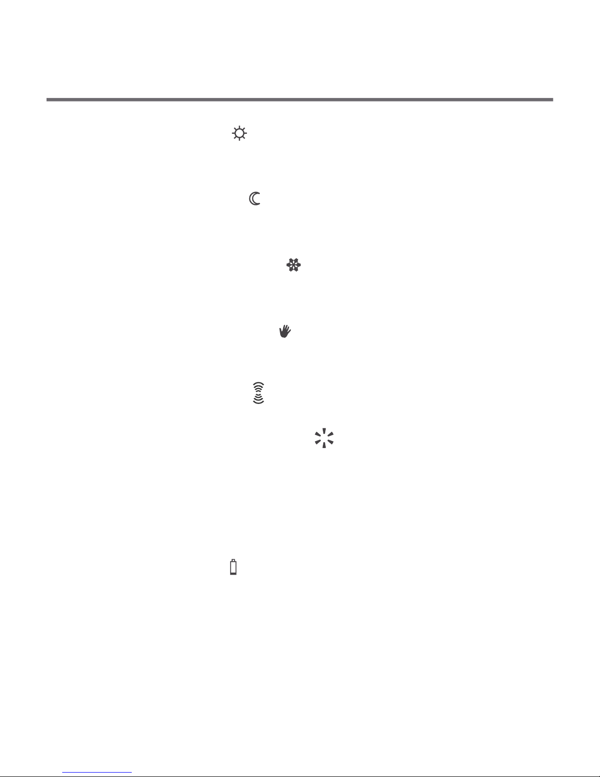
6. Day mode indicator ( )
Indicates that the controller is in the day mode.
(see: "Temperature programming")
7. Night mode indicator ( )
Indicates that the controller is in the night mode.
(see: "Temperature programming")
8. Anti-freeze mode indicator ( )
Indicates that the controller is in the anti-freeze mode.
(see: "Anti-freeze mode”)
9 . Manual control indicator ( )
Appears if the programmed mode is switched off.
(see: "Manual control mode”)
11. Controller power on indicator ( )
Indicates the operating status. Visible when the controlled device
is started.
12. Program number
Indicates the number of program currently executed.
(see: "Factory programs" and "Weekly programming")
13. Battery exhausted ( )
Displayed when the battery voltage drops below the allowed
limit. Replace the battery as soon as possible.
NOTE: To save the parameters programmed, the battery
exchange operation should not last longer than 30 seconds.
10. ( ) – AURATON 3021R onlyTransmission symbol
Indicates ongoing communication with the RTH receiver.
Display
1. Day of week ( ) Indicates the current day of the week.
Each day has a number assigned.
2. – In normal operating mode, the controller displays
the temperature of the room it is installed in.
3.Temperature unit – Indicates temperature displayed in
centigrade ( ).
4. Clock – Time displayed in 24-hour mode.
5. Timeline – Program progress indicator. Line divided to 24
sections, each corresponding to one hour. Indicates program
execution method. (see: "Timeline")
–
Temperature