In order to delete (log-out) a device from the selected zone, perform the following
procedures:
1. If the zone with a paired LMS device is known, press the button of this zone and keep it
pressed longer than 5sec. After 3 seconds a single acoustic signal is emitted – do not
release the button and after the next 2seconds a double acoustic signal is emitted – the
zone automatically enters deleting mode (the display will show the antenna symbol).
After one zone is entered into deleting mode, other zones may enter this mode by short
pressing the respective zone button. It enables the user to delete a device from more
than one zone.
2. Then, in order to delete a LMS wireless devices (e.g. temperature regulator) from the
zone, activate “deleting” mode in LMS wireless device (detailed instructions on
activating "deleting" mode in a selected device is in its manual).
3. If the LED for selected zone stops blinking, it means that all LMS devices in that zone have
been correctly deleted.
When a LED of any zone continues to blink after deleting process, it means that the
controller waits for deleting other LMS devices.
NOTE: Deleting process in selected zone turns off automatically after 60s.
Deleting wireless devices (LMS) from a zone
In order to delete all LMS from AURATON 8000, proceed as
follows:
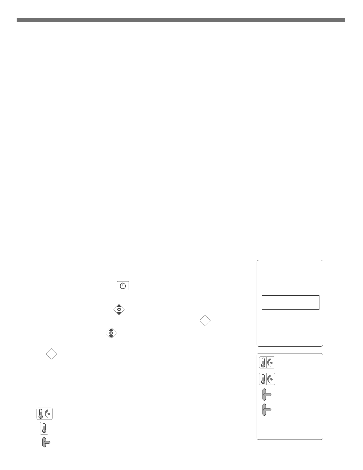
1. Press ON/OFF button (single acoustic signal is emitted).
The display will show a pick list.
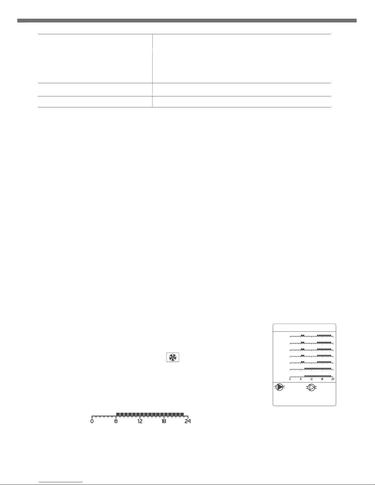
2. Use the controller (up & down) to select “Delete
wireless devices”, and the confirm it by pressing .
3. Use the controller (up & down) to select the device to be
deleted from the pick list. Confirm the selection by pressing
or 3 seconds.
[pow]
[kon]
[KO]
[KO]
[ko]
f
Deleting wireless devices (LMS) using a list
OK
OK
NOTE: After selecting a device from the list, LEDs are
activated next to the zone to which the device is
paired.
AURATON
8000
Cancel
Delete wireless
devices
< English >
Turn off
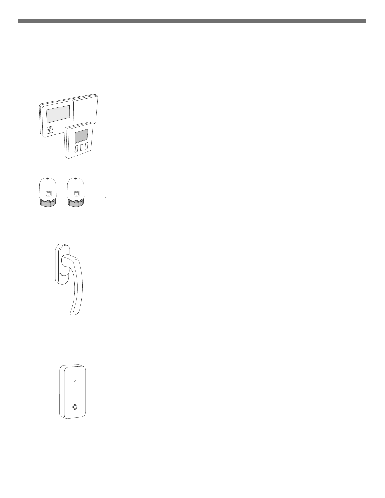
Pairing wireless devices to a zone
In order to pair wireless temperature sensors, thermostats or LMS window handles with the
selected zone perform the following procedures:
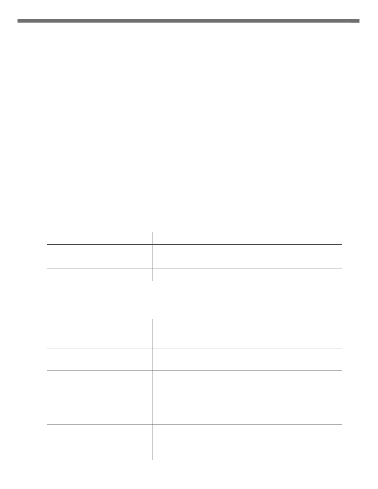
1. Press the button of a selected zone for 3s, wait for
a single acoustic signal and then release the button. Entering the
zone into pairing mode is signalled by pulsating LED of this zone
(every 0.5s) and by displayed antenna symbol on the display.
After a zone enters the pairing mode, other zones may be also
entered into this mode by briefly pressing the button of any
other zone. This enables the user to simultaneously pair the
same thermostat and/or thermometer to more than one zone.
2. Then, in order to pair a LMS wireless device (e.g. temperature
regulator) to the zone, run "pairing" mode in the selected LMS
wireless device (detailed instructions on activating "pairing"
mode in a selected device is in its manual).
3. Correct pairing of a LMS device is confirmed by a 1-second
acoustic signal.
4. When the button of the zone in "pairing" mode is shortly
pressed, then the "pairing" mode is turned off.
5. When the „pairing" mode is turned off in all zones, A8000 enters
the mode of normal operation.
NOTE: The "pairing" mode is automatically switched off 60 seconds after the last zone is
entered or after correctly completed pairing of a LMS device or after a short
press of the selected zone button.
NOTE: One zone may be paired only with one thermostat. Remember that, after pairing a
zone with a new thermostat, the thermostat paired previously with this zone will
be deleted.
NOTE: If the zone was paired with a thermostat and then with a thermometer, then the
zone will log-in both devices. The set temperature will be read from the
thermostat, and the actual temperature from the thermometer. One zone may be
paired only with one thermostat and/or thermometer.
( )[1 ]...[8 ]
67
- temperature controller symbol
- thermometer symbol
- window handle symbol
ID: 0243DB60
ID: 01313094
ID: 01C9D186
ID: AAFC9022