AURATON Cetus User manual

26/10/21, 3:26 μ.μ.
AURATON Cetus - AURATON manuals
https://manuals.auraton.pl/manuals/auraton-cetus-pl/
1/27
AURATON Cetus
A daily, wired temperature controller
Description of AURATON Cetus
The first launch of AURATON Cetus
"Manual" mode setting
FrostGuard function
Hysteresis change
PWM operating mode
Remarks
Connection diagram of AURATON Cetus
Cleaning and maintenance
Technical data
Disposal of the device
To download

26/10/21, 3:26 μ.μ.
AURATON Cetus - AURATON manuals
https://manuals.auraton.pl/manuals/auraton-cetus-pl/
2/27
User manual ver. 20200926
The document contains information on the safety, installation and use of the AURATON
Cetus device.
A daily, wired temperature controller
AURATON Cetus is a daily, wired, temperature controller, designed to work with a gas
or electric heating device.
AT FrostGuard function.
Protection against freezing of the room.
&Possibility of temporarily lowering the programmed
temperature
For a maximum period of 12 hours.
WITH Vacation mode
Up to eight days independent of the programmed
temperature.
LCD
Backlit LCD display The
backlit display enables the device operation supervision
even in poorly lit rooms.
A daily, wired temperature controller
Description of AURATON Cetus
The first launch of AURATON Cetus
"Manual" mode setting
FrostGuard function
Hysteresis change
PWM operating mode
Remarks
Connection diagram of AURATON Cetus
Cleaning and maintenance
Technical data
Disposal of the device
To download

26/10/21, 3:26 μ.μ.
AURATON Cetus - AURATON manuals
https://manuals.auraton.pl/manuals/auraton-cetus-pl/
3/27
Description of AURATON Cetus
daily, wired temperature controller
On the front part of the controller housing there is a backlit LCD display, four function
buttons and a temperature setting knob with a button ( .
A daily, wired temperature controller
Description of AURATON Cetus
The first launch of AURATON Cetus
"Manual" mode setting
FrostGuard function
Hysteresis change
PWM operating mode
Remarks
Connection diagram of AURATON Cetus
Cleaning and maintenance
Technical data
Disposal of the device
To download

26/10/21, 3:26 μ.μ.
AURATON Cetus - AURATON manuals
https://manuals.auraton.pl/manuals/auraton-cetus-pl/
4/27
1. LCD display
2. Setting knob with integrated push button (
3. On / off button regulator
4. Manual mode button
5. "Temporary temperature reduction" button
6. Temperature setting button
Display
A daily, wired temperature controller
Description of AURATON Cetus
The first launch of AURATON Cetus
"Manual" mode setting
FrostGuard function
Hysteresis change
PWM operating mode
Remarks
Connection diagram of AURATON Cetus
Cleaning and maintenance
Technical data
Disposal of the device
To download

26/10/21, 3:26 μ.μ.
AURATON Cetus - AURATON manuals
https://manuals.auraton.pl/manuals/auraton-cetus-pl/
5/27
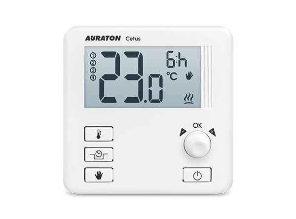
1. Temperature - In the normal operation mode, AURATON Cetus displays the
temperature of the room in which it is installed.
2. Battery exhausted ( X )
The indicator is visible when the minimum permissible battery voltage is exceeded.
Replace the batteries as soon as possible.
NOTE: To maintain the programmed parameters, the time of the battery
replacement operation should not exceed 30 seconds.
3. Temporary temperature reduction duration indicator
Shows how long the temporary temperature reduction mode will remain active.
4. Temperature unit
Indicates that the temperature is displayed in degrees Celsius ( R ).
5. Manual mode indicator ( V )
Indicates that you are in manual (vacation) temperature setting.
6. Temporary temperature reduction mode programming indicator ( S )
Indicates the user scheduled "temporary temperature reduction" mode. It appears
when the mode is not currently implemented, but the "temporary temperature
reduction" function is active. (more information in the chapter "Setting the temporary
temperature reduction mode")
7. AURATON Cetus activation indicator ( a )
Pictogram informing about the operating status of the device. Visible when the
controlled device is turned on.
8. Temporary temperature decrease mode indicator ( T )
Appears while the temporary temperature decrease program is running.
A daily, wired temperature controller
Description of AURATON Cetus
The first launch of AURATON Cetus
"Manual" mode setting
FrostGuard function
Hysteresis change
PWM operating mode
Remarks
Connection diagram of AURATON Cetus
Cleaning and maintenance
Technical data
Disposal of the device
To download

26/10/21, 3:26 μ.μ.
AURATON Cetus - AURATON manuals
https://manuals.auraton.pl/manuals/auraton-cetus-pl/
6/27
9. Number of days in "vacation" mode ( 8 )
Indicates the number of days for which vacation mode is scheduled.
Choosing the right location for AURATON Cetus
A daily, wired temperature controller
Description of AURATON Cetus
The first launch of AURATON Cetus
"Manual" mode setting
FrostGuard function
Hysteresis change
PWM operating mode
Remarks
Connection diagram of AURATON Cetus
Cleaning and maintenance
Technical data
Disposal of the device
To download

26/10/21, 3:26 μ.μ.
AURATON Cetus - AURATON manuals
https://manuals.auraton.pl/manuals/auraton-cetus-pl/
7/27
The correct operation of AURATON Cetus is largely influenced by its location. Location
in a place with no air circulation or direct sunlight may result in incorrect temperature
control. AURATON Cetus should be installed on the internal wall of the building
(partition wall), in an environment of free air circulation. Avoid proximity to heat emitting
devices (TV, heater, refrigerator) or locations exposed to direct sunlight. Problems in
proper operation may be caused by the vicinity of the door, exposing AURATON Cetus
to possible vibrations.
Connecting cables to AURATON Cetus
To connect the wires, remove the cover as shown below:
The cable clamps are located on the back of the AURATON Cetus, under the plastic
cover.
A daily, wired temperature controller
Description of AURATON Cetus
The first launch of AURATON Cetus
"Manual" mode setting
FrostGuard function
Hysteresis change
PWM operating mode
Remarks
Connection diagram of AURATON Cetus
Cleaning and maintenance
Technical data
Disposal of the device
To download

26/10/21, 3:26 μ.μ.
AURATON Cetus - AURATON manuals
https://manuals.auraton.pl/manuals/auraton-cetus-pl/
8/27
1. cover
2. screw
3. wire clamps
A daily, wired temperature controller
Description of AURATON Cetus
The first launch of AURATON Cetus
"Manual" mode setting
FrostGuard function
Hysteresis change
PWM operating mode
Remarks
Connection diagram of AURATON Cetus
Cleaning and maintenance
Technical data
Disposal of the device
To download

26/10/21, 3:26 μ.μ.
AURATON Cetus - AURATON manuals
https://manuals.auraton.pl/manuals/auraton-cetus-pl/
9/27
It is a typical single-pole two-state relay. In most cases, the NC terminal is not used.
NOTE:
After connecting the wires, put the plastic cover back on.
Battery change
The battery socket is located inside the AURATON Cetus on the front of the housing. To
install the batteries, remove the controller housing as shown in the chapter "Connecting
the cables to the AURATON Cetus".
NOTE:
We recommend alkaline batteries to power AURATON regulators. Do not use
"rechargeable batteries" because the rated voltage is too low.
A daily, wired temperature controller
Description of AURATON Cetus
The first launch of AURATON Cetus
"Manual" mode setting
FrostGuard function
Hysteresis change
PWM operating mode
Remarks
Connection diagram of AURATON Cetus
Cleaning and maintenance
Technical data
Disposal of the device
To download

26/10/21, 3:26 μ.μ.
AURATON Cetus - AURATON manuals
https://manuals.auraton.pl/manuals/auraton-cetus-pl/
10/27
1. - 1.5V AAA battery socket
Insert two AAA 1.5V batteries into the battery socket, paying attention to the correct
polarity of the batteries.
A daily, wired temperature controller
Description of AURATON Cetus
The first launch of AURATON Cetus
"Manual" mode setting
FrostGuard function
Hysteresis change
PWM operating mode
Remarks
Connection diagram of AURATON Cetus
Cleaning and maintenance
Technical data
Disposal of the device
To download

26/10/21, 3:26 μ.μ.
AURATON Cetus - AURATON manuals
https://manuals.auraton.pl/manuals/auraton-cetus-pl/
11/27
NOTE:
After replacing the battery and folding the housing, we recommend pressing the
button twice ( to stabilize the relay operation.
Mounting AURATON Cetus - a daily, wired
temperature controller
To fix the AURATON Cetus controller to the wall:
1. Remove the regulator casing (as shown in the section "Connecting the cables to the
AURATON Cetus")
2. Drill two holes 6 mm in diameter in the wall (mark the spacing between the holes
using the rear part of the AURATON Cetus housing).
3. Put the wall plugs in the drilled holes.
4. Screw the rear part of the AURATON Cetus housing to the wall using the screws
included in the kit.
5. Put the AURATON Cetus housing on.
NOTE:
In the case of a wooden wall, there is no need to use expansion bolts. It is enough
to drill holes with a diameter of 2.7 mm (instead of 6 mm) and screw the screws
directly into the wood.
A daily, wired temperature controller
Description of AURATON Cetus
The first launch of AURATON Cetus
"Manual" mode setting
FrostGuard function
Hysteresis change
PWM operating mode
Remarks
Connection diagram of AURATON Cetus
Cleaning and maintenance
Technical data
Disposal of the device
To download

26/10/21, 3:26 μ.μ.
AURATON Cetus - AURATON manuals
https://manuals.auraton.pl/manuals/auraton-cetus-pl/
12/27
1. fixing screw hole
Putting the cover on: NOTE
When putting the front part of the housing back on the rear part, pay attention to the
pins that control the relay.
A daily, wired temperature controller
Description of AURATON Cetus
The first launch of AURATON Cetus
"Manual" mode setting
FrostGuard function
Hysteresis change
PWM operating mode
Remarks
Connection diagram of AURATON Cetus
Cleaning and maintenance
Technical data
Disposal of the device
To download

26/10/21, 3:26 μ.μ.
AURATON Cetus - AURATON manuals
https://manuals.auraton.pl/manuals/auraton-cetus-pl/
13/27
1. Front housing
2. Rear housing
3. Pins
4. Pin connector socket or the place where pins contact the board
ATTENTION:
When assembling the housing, make sure that the connection "pins" are not bent
and fall into their place on the relay board. This is crucial for the proper operation of
the regulator.
The first launch of AURATON Cetus
A daily, wired temperature controller
Description of AURATON Cetus
The first launch of AURATON Cetus
"Manual" mode setting
FrostGuard function
Hysteresis change
PWM operating mode
Remarks
Connection diagram of AURATON Cetus
Cleaning and maintenance
Technical data
Disposal of the device
To download

26/10/21, 3:26 μ.μ.
AURATON Cetus - AURATON manuals
https://manuals.auraton.pl/manuals/auraton-cetus-pl/
14/27
After the batteries are properly inserted
into the sockets, all segments (display
test) will appear on the LCD display for
a second, followed by the software
version number (eg F12).
After a while, the current room
temperature will be displayed
automatically. AURATON Cetus is
ready to work.
Temperature setting
NOTE:
The first pressing of any function button always turns on the backlight, and only the
next call of the button function.
After a while, the current room temperature will be displayed automatically. AURATON
Cetus is ready to work. To set the desired temperature in the normal operation mode:
1. Press the n button . The segment
displaying the current room
A daily, wired temperature controller
Description of AURATON Cetus
The first launch of AURATON Cetus
"Manual" mode setting
FrostGuard function
Hysteresis change
PWM operating mode
Remarks
Connection diagram of AURATON Cetus
Cleaning and maintenance
Technical data
Disposal of the device
To download

26/10/21, 3:26 μ.μ.
AURATON Cetus - AURATON manuals
https://manuals.auraton.pl/manuals/auraton-cetus-pl/
15/27
&
temperature will start blinking.
2. By turning the knob to the left or
right, with an accuracy of 0.2 ° C,
you set the desired temperature in
the room.
3. Confirm the selection with the button
(
Setting the "temporary temperature reduction"
mode
If, for various reasons, we would like to lower the temperature in the room at
a certain time of the day, it is possible to temporarily reduce it by a maximum
of 5 ° C. To do this:
1. Press and hold the & button
for 3 seconds . The display will
show the moon ( T ), the hour field
(e.g. * ), and the segment
responsible for showing the
temperature will enter the edit mode
and start blinking.
A daily, wired temperature controller
Description of AURATON Cetus
The first launch of AURATON Cetus
"Manual" mode setting
FrostGuard function
Hysteresis change
PWM operating mode
Remarks
Connection diagram of AURATON Cetus
Cleaning and maintenance
Technical data
Disposal of the device
To download

26/10/21, 3:26 μ.μ.
AURATON Cetus - AURATON manuals
https://manuals.auraton.pl/manuals/auraton-cetus-pl/
16/27
2. By turning the knob to the left or
right, we set the temperature
reduction by a value from 1 ° C to 5
° C. Confirm the selection with the
button ( .
3. The hour field on the display changes to edit mode and starts blinking. Using the
knob again, we set the number of hours for which the reduced temperature
programmed by us is to apply. You can choose from 1 to 12 hours. Confirm your
selection by pressing ( .
4. For the selected number of hours, AURATON Cetus will be in the "temporary
temperature reduction" mode and will start it every day at the same time.
NOTE:
After the set hourly time, AURATON Cetus will return to the basic temperature
setting. Instead of the moon ( T ), the sun ( S )will appear on the screen
NOTE:
The temporary temperature reduction mode always starts at the moment of
confirming the edition of the function. This means that any temporary temperature
reduction should be programmed at a time when we want such a change to take
place.
A daily, wired temperature controller
Description of AURATON Cetus
The first launch of AURATON Cetus
"Manual" mode setting
FrostGuard function
Hysteresis change
PWM operating mode
Remarks
Connection diagram of AURATON Cetus
Cleaning and maintenance
Technical data
Disposal of the device
To download

26/10/21, 3:26 μ.μ.
AURATON Cetus - AURATON manuals
https://manuals.auraton.pl/manuals/auraton-cetus-pl/
17/27
V
Disabling the "temporary temperature reduction"
AURATON Cetus will implement the programmed temporary temperature reduction
mode every day at the same time until the temporary temperature reduction is not
turned off. Exclusion is the repeated pressing and holding the button for 3 seconds
& .
"Manual" mode setting
If we want to temporarily suspend the normal or temporarily reduced
temperature, it is possible to set the "manual" program, valid for a maximum of 8
days. To do this:
1. Press the o button .
The hand symbol ( V ) will appear
on the display , and the segment
responsible for showing the current
temperature will enter the edit mode
and start blinking.
2. By turning the knob to the left or
A daily, wired temperature controller
Description of AURATON Cetus
The first launch of AURATON Cetus
"Manual" mode setting
FrostGuard function
Hysteresis change
PWM operating mode
Remarks
Connection diagram of AURATON Cetus
Cleaning and maintenance
Technical data
Disposal of the device
To download

26/10/21, 3:26 μ.μ.
AURATON Cetus - AURATON manuals
https://manuals.auraton.pl/manuals/auraton-cetus-pl/
18/27
right, we set the desired
temperature value. Confirm the
selection with the button ( .
3. The hour field on the display
changes to edit mode and starts
blinking. You can use the knob to
select the number of hours during
which the manual temperature
setting is to apply. Days are added
or subtracted automatically when
the value of 24 hours is exceeded.
You can select a maximum of 7
days and 24 hours. Confirm your
selection by pressing ( .
NOTE:
Manual mode is not automatically repeated. After the programmed time has
elapsed, AURATON Cetus returns to the implementation of previous temperature
programs: normal mode and temporary temperature reduction, if the latter was
previously planned.
A daily, wired temperature controller
Description of AURATON Cetus
The first launch of AURATON Cetus
"Manual" mode setting
FrostGuard function
Hysteresis change
PWM operating mode
Remarks
Connection diagram of AURATON Cetus
Cleaning and maintenance
Technical data
Disposal of the device
To download

26/10/21, 3:26 μ.μ.
AURATON Cetus - AURATON manuals
https://manuals.auraton.pl/manuals/auraton-cetus-pl/
19/27
Early deactivation of the "manual" mode
AURATON Cetus will continue the programmed manual mode until the programmed
time has elapsed. To deactivate the "manual" mode, press the o button again .
Checking the set temperature
Holding down the button ( for at least 2 seconds allows you to check the currently
programmed temperature of the controller. Correct performance of the operation results
in the display of a flashing segment responsible for showing the set temperature of the
device. The function is active in each of the AURATON Cetus operating modes.
FrostGuard function
AURATON Cetus is equipped with a special FrostGuard function that protects the room
against possible freezing. This function is activated when AURATON Cetus is turned
off .
With AURATON Cetus turned off, when the temperature in the room drops to 2 ° C, the
symbols ( ! ) And ( a ) appear on the display and the relay will turn on. When the
temperature rises to 2.2 ° C, the display will turn off again and the relay will disconnect
the contacts.
A daily, wired temperature controller
Description of AURATON Cetus
The first launch of AURATON Cetus
"Manual" mode setting
FrostGuard function
Hysteresis change
PWM operating mode
Remarks
Connection diagram of AURATON Cetus
Cleaning and maintenance
Technical data
Disposal of the device
To download

26/10/21, 3:26 μ.μ.
AURATON Cetus - AURATON manuals
https://manuals.auraton.pl/manuals/auraton-cetus-pl/
20/27
Hysteresis change
The hysteresis is to prevent too frequent switching on of the actuator due to small
temperature fluctuations.
For example, for the HI 2 hysteresis, when the temperature is set to 20 ° C, switching
on will take place at 19.8 ° C, and switching off at 20.2 ° C. For the HI 4 hysteresis,
when the temperature is set to 20 ° C, switching on will take place at 19.6 ° C, and
switching off at 20.4 ° C.
To switch to the hysteresis change
mode, hold down the o , & and
a buttons simultaneously for 3
seconds.
The hysteresis change mode is signaled by the flashing text HI. Turn the knob to the left
or right to set the required hysteresis.
HI 2 - ± 0.2 ° C (factory set),
HI 4 - ± 0.4 ° C,
HI P - PWM operating mode (chapter "PWM operating mode").
Confirm the selection by pressing the button ( . The controller will return to normal
operation.
A daily, wired temperature controller
Description of AURATON Cetus
The first launch of AURATON Cetus
"Manual" mode setting
FrostGuard function
Hysteresis change
PWM operating mode
Remarks
Connection diagram of AURATON Cetus
Cleaning and maintenance
Technical data
Disposal of the device
To download
Table of contents
Other AURATON Temperature Controllers manuals
Popular Temperature Controllers manuals by other brands

Alpes Lasers
Alpes Lasers TC-3 user manual

Nibe
Nibe POOL 40 Installer manual

La Crosse Technology
La Crosse Technology TX4 instruction manual

Sterlco
Sterlco Sterlco M-8414 Service and instruction manual

Control Company
Control Company TRACEABLE 4130 instructions

Vestamatic
Vestamatic Markise Plus 500 V2.0 Installation and operating instructions