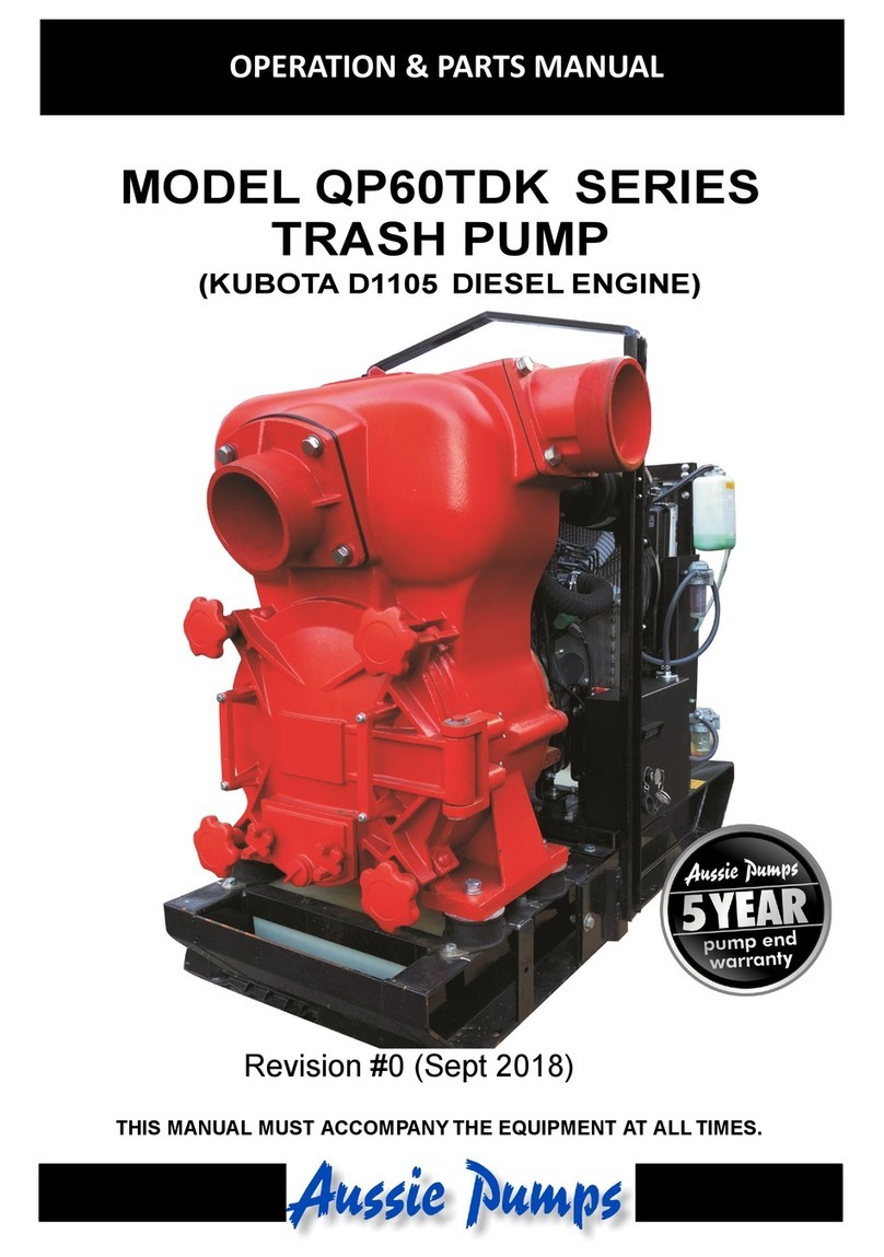
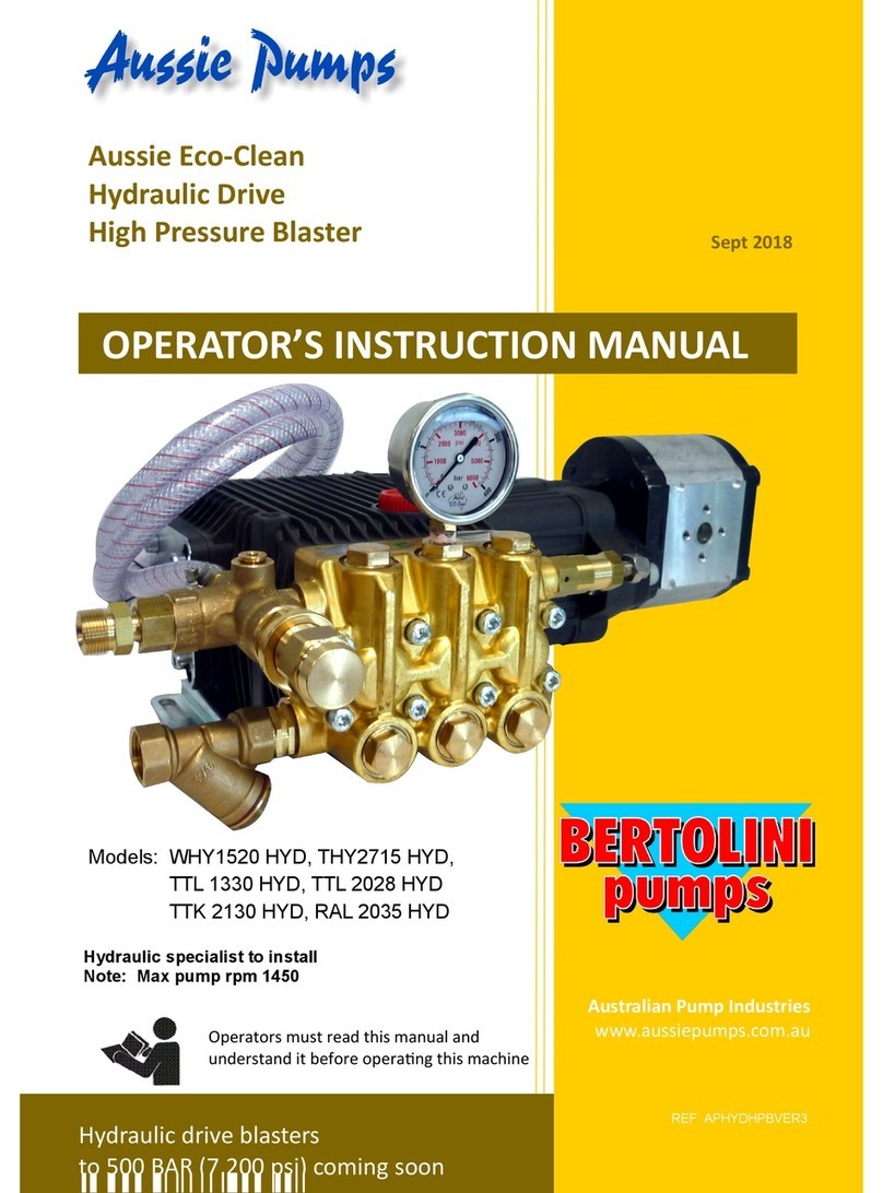
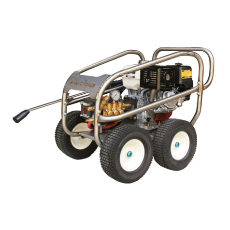
Aussie Pumps QP User manual

Australian Pump Industries
Page 1 document number: QPWP151204
AUSTRALIAN PUMP
QP WATER PUMP
Inspect Unit for shipping damage immediately upon receipt. If any damage
exists note damage on shipping docket before signing. Notify your Distributor
immediately of any damage to shipment.
INSTALLATION, OPERATION AND MAINTENANCE MANUAL
Installation
Location
The pump should be located as near as possible to the liquid
to be pumped and in no case should the pump be more than
7m (23 feet) above the surface of the liquid supply. The
pump should always be as level as possible.
Suction System
Connect horizontal suction hose or pipe to suction flange.
Pipe or hose must be self supporting without adding stress
to pump body. If a hose is used, it should be of the
reinforced type to prevent collapsing under vacuum. All
suction system pipe or hose and connections must be free of
air leaks, as even a very slight leak will greatly reduce
pumping efficiency and priming ability. The pump should be
installed with the trash strainer on the suction line to prevent
oversize solids from being drawn into the suction system.
Discharge System
Connect discharge hose or pipe to discharge elbow on top of
the pump body.
Operation
Priming
Remove the flooding cap at the top of the casing and screw
it back tightly after filling up the casing with priming water.
(Open the gate valve on the delivery line, if so equipped.) In
freezing weather use warm water if possible, to prevent
damage to internal parts from ice. At each subsequent start,
check priming liquid level in pump body since the pump is
self-priming only when the body is full of liquid.

Australian Pump Industries
Page 2 document number: QPWP151204
B-2 Tightening Couplings
To prevent air entry or water leakage, tighten the couplings
thoroughly.
B-3 Strainer
Always fit strainer to end of suction line and hold it with the
tightening band. The strainer should be regularly checked and
cleaned out to insure full liquid flow at all times.
B-4 Starting
The pump is ready for operation after completion of the
procedures outlined. Start pump by starting the engine as
outlined in the Engine Instruction Manual. Open fuel cock, close
engine choke, start engine.
NOTE: QP pumps are self priming and no additional
priming is required as long as the casing is filled
with water and there are no suction line leaks.
B-5 Shutdown
Operation is stopped by stopping the engine as outlined in the
Engine Instruction Manual. Always operate at no load for 2 or 3
minutes to allow cooling before shutdown. When the pump has
been operating in freezing weather or in pumping liquid
containing considerable amounts of trash and /or foreign matter,
it is advisable to remove both the drain plug and the prime plug
and allow the body to drain. Flush solids out of the pump body.
Replace plugs.
Caution!
1. If flexible hose is laid across a
roadway protect if with
planking. Instantaneous shut
off pressure is applied when a
vehicle runs across an
unprotected hose and will
cause ‘hydraulic shock’. This
can damage the pump and/or
the hose.
2. A relief valve should be used to
avoid ‘hydraulic shock’ if
sudden “shut off” cannot be
avoided.
3. Do not use QP Pumps with
pressure feed e.g. from a fire
hydrant.

Australian Pump Industries
Page 3 document number: QPWP151204
DISASSEMBLY & ASSEMBLY
For centrifugal transfer pumps
Check Valve
a. Unscrew suction cover set bolt or screw, and remove the suction cover.
b. Unscrew the set bolt or screw with washer, and remove the check valve.
c. For setting the new check valve, screw the set bolt or screw to fit the valve
with valve seat of suction cover.
d. Install the suction cover with O-ring or packing.
a. Volute Casing
a. Unscrew the casing set bolt, and remove the casing from the casing cover.
b. Remove the volute casing that is placed into casing cover.
c. Install the new volute casing with O-ring or packing into the casing cover
correct position.
d. Adjust the clearance between front surface of impeller and side plate volute
casing to be within 0.2 to 0.5mm (0.008 to 0.020 inch) when the volute casing
is pushed in by adjusting the number of adjusting liners at impellerboss.
e. After confirming the volute casing to the casing cover, and screw the casing
set bolts evenly and tightly.
b. Impeller
a. Disclose the impeller by removing the volute casing same way as above.
b. Loosen the impeller by tapping gently with a mallet in a counter clockwise
direction.
c. Turn impeller counter clockwise, and remove from shaft.
d. Remove the mechanical seal from the impeller, and set it at the back side of
new impeller.
e. Screw the new impeller on engine shaft by turning in the clockwise direction,
and make it tight by tapping gently with mallet in a clockwise direction.
f. Set the volute casing and casing as mentioned above
c. Mechanical Seal
a. Remove the impeller as mentioned above
b. Replace with a new mechanical seal at the back side of removed impeller
and at the seat of casing cover.
c. Check the scaling surfaces of mechanical seal free dust, and set the impeller,
volute casing and casing as in the way abovementioned 3.
For Trash Pumps
Clogged Impeller
a. Unscrew drain set handles and dismantle the drain cover from casing.
b. Dismantle volute casing.
c. Wash impeller with water.
d. Place volute casing O-ring and drain cover O-ring and screw drain cover after
washing sealing surface with water.
e. Screw drain cover set handle evenly at right and left side.

Australian Pump Industries
Page 4 document number: QPWP151204
Impeller
a. Dismantle the drain cover and volute casing as described above 1.
b. The impeller is now exposed
c. Impeller is attached to the engine shaft with a screw.
d. Tap the impeller at the lead part in counter-clockwise direction with a mallet
e. Screw new impeller on shaft by hand, and tighten by using a mallet, tapping
at the lead part of the impeller in a clockwise direction.
Check Valve
a. Unscrew suction cover set nut or cap-screw, and remove suction cover.
b. Unscrew check valve set bot or screw with washer at the back of the suction
cover.
Mechanical Seal
c. Dismantle the impeller as above.
d. D. Remove the mechanical seal sleeve from the shaft.
e. Mechanical seal rotary section and spring will be removed with the sleeve.
f. Remove mechanical seal stationary section from the seat of casing cover.
g. Set the new mechanical seal sleeve to the shaft after assembled with new
rotary section spring. (Check to see if the mechanical seal O-ring is placed
correctly to the seat)
h. Set new mechanical seal rotary section and spring with the sleeve to fit the
slit of the sleeve with spring stopper.
i. Screw the impeller as described above.
Troubleshooting
PROBLEM CAUSE REMEDY
Pump does not turn over Impeller jamming Adjust impeller spacing,
disassemble and clean
Air leak on suction side Check fitting and piping on
suction side. Replace if
necessary.
Reduction of engine
performance/rpm
Take to engine repair Agent
Damaged mechanical seal Relace mechanical seal
Excessive suction lift Move pump closer to liquid
Leaking water Take to Aussie Pump
repairer
Clogging of foreign
substance in impeller
Disassemble and clean
Pumping volume is lower
than normal
Wear of impeller Replace impeller
Suction of air on suction side Check hoe and fitting at
suction side
Insufficient priming water
inside pump casing
Prime fully
Loose drain plugs Tighten the 2 plugs
completely
Engine loses performance Take to engine repairer
Pump does not self prime
Sucking air from mechanical
seal
Replace mechanical seal

Australian Pump Industries
Page 5 document number: QPWP151204
PUMP SAFETY
This symbol, the industry’s “Safety Alert Symbol”, is used throughout this
pamphlet and on the pump’s safety labels to warn of the possibility of personal
injury. We request that you take special care in reading and understanding the
safety precautions before operating the pumps or its equipment.
CAUTION
MECHANICAL SEAL WILL BE SEVERELY DAMAGED,
IF PUMP IS RUN DRY WITHOUT PRIMING WATER.
PUMP SAFETY PRECAUTIONS
A. GENERAL
1. USE COMMON SENSE! Most accidents can be avoided by using
common sense and concentrating on the job to be done.
2. Do not wear loose clothing that can become entangled in operating
machinery.
3. Do not operate pump without guards in place.
4. Do not pump hazardous material. (flammable, caustic, etc.)
5. Only qualified personnel should install and operate pump.
6. Secure the pump after it is in its operating position so it does not tip
over, roll, slide, or fall.
7. Read the maintenance and operating instruction manual supplied
with the pump.
8. Keep hands and feet clear of moving parts. DO NOT stick hands or
fingers in pump when operating.
PLESE TAKE THE TIME TO READ THIS
PAMPHLET BEFORE OPEATING PUMP

Australian Pump Industries
Page 6 document number: QPWP151204
9. Do not close down or restrict discharge hose. Be careful of
discharge hose whipping under pressure.
10. PUMP TOWED BEHIND VEHICLE
a. Make sure hitch is properly attached.
b. Always attach safety chains.
c. Check tires for proper inflation and road worthiness.
d. If towing on the highway, make sure the trailer meets Department
of Transportation requirements.
11. Make sure lifting device’s fasteners are tight each time before lifting.
B. GAS/DIESEL ENGINE POWERED PUMPS
1. EXHAUST GASES
a. Never operate in an enclosed building or area where exhaust gases
can accumulate.
b. Do not breathe exhaust fumes when working in the area of the
engine. (Exhaust gases are colourless, odourless and deadly
poison.)
c. Never operate near a building where exhaust gases can seep inside,
for example: through an open window or a door.
d. Never operate in a pit or sump without making provisions to suck the
exhaust gases out.
2. EXHAUST SYSTEM
a. Keep exhaust system components tight and in good working
condition.
b. Exhaust system parts get very hot and stay hot for some time after
shutting the engine off – do not touch.
3. FUEL
a. Never add fuel to the tank while the engine is running. Stop engine
and allow it cool. Avoid spilling fuel!
b. Make sure fuel lines and fittings are tight and in good condition.
c. Do not smoke while refuelling the engine.
d. Do not refuel near open flame; wipe up all spilled fuel.
e. Store gasoline in approved container and location.

Australian Pump Industries
Page 7 document number: QPWP151204
4. MAINTENANCE AND REPAIR
a. Disconnect spark plug wire while performing maintenance or repair
on the pump or engine.
b. Always replace safety devices removed during service or repair
before operating.
5. 12-VOLT ELECTRICAL SYSTEM
a. Connect negative battery lead to ground to prevent damage to
charging system.
b. To prevent arcing, when removing battery, disconnect negative lead
first. When replacing battery, connect negative lead last.
c. Do not spill battery acid. If spilled, rinse off immediately with water.
6. DIESEL
Follow engine manufacturer instructions explicitly on hand cranking.
7. OVERHEATING – DO NOT RUN THE PUMP FOR OVER TEN MINUTES
WITHOUT WATER FLOWING THROUGH IT!
Overheating pumps can cause severe burns and injury. If overheating
of pump casing occurs:
a. Stop the pump immediately.
b. Allow the pump to cool completely.
c. Slowly and cautiously vent the pump.
C. ELECTRIC MOTOR POWERED PUMPS
1. GROUND FAULT CIRCUIT INTERRUPTER
Never operate a pump with a plug-in type power cord without a ground
fault circuit interrupter.
2. WET HANDS
Never handle energized power cords with wet hands.
3. WATER
Never let extension cords or the plug connection lay in water. Locate
the pump such that it cannot fall into the water (except when using the
Submersible pumps.)
4. EQUIPMENT
Never use cords with frayed or cut or brittle insulation. Check the cord
on the pump for nicks in the insulation and for sound connections to
the ground fault interrupter plug and motor.
5. QUALIFIED ELECTRICIAN
Any wiring to be done on pumps should be done by a qualified
electrician.

Australian Pump Industries
Page 8 document number: QPWP151204
CARE OF ATTENTION, CAUTION LABELS
1) Always keep labels clean without stain or
mud to clearly recognize the caution details.
2) Use new labels if original labels have become
obliterated.
3) Certainly stick the labels on the same place
as before when parts with labels are changed
by repairing something.
6. LIFTING THE PUMP
Never use the cord to aid in lifting the pump.
7. PUMP MAINTENANCE AND REPAIR
Be sure the pump is disconnected from the power of the appropriate
circuits are dead and locked out before doing any maintenance or repair
work on the pump.
8. MOTOR OVERLOAD
Do not exceed the manufacturer’s recommendation for maximum lift or
discharge head, as this could cause the motor to overheat. Use
appropriate circuit breaker for fuse.
9. EXPLOSIVE ATMOSPHERE
Unless the pump has been designed for it, never use it in any kind of
possible explosive atmosphere.
CAUTION: Irrespective of pump material of construction or
elastomer type, ALWAYS flush pump with fresh water after
use if other than clean fresh water has been pumped.
AUSTRALIAN PUMPS INDUSTRIES
7 GLADSTONE ROAD CASTLE HILL NSW 2154
Ph (02) 9894 4144 Fax: (02) 9894 4240 Email: wlorenz@aussiepumps.com.au
RELIABLE PRODUCTS…………………………………….RELIABLE PEOPLE
Table of contents
Other Aussie Pumps Water Pump manuals
Popular Water Pump manuals by other brands
Grundfos
Grundfos MAGNA1 C Installation and operating instructions

Server
Server SERVE BETTER CP-1/3 2oz manual

SGS
SGS SWP80 owner's manual

GORMAN-RUPP PUMPS
GORMAN-RUPP PUMPS 82D1-L70W FT4-X Installation, operation and maintenance manual

DECCAN
DECCAN DOUBLE STAGE JET PUMP Installation & operation manual

Edwards
Edwards EXT400/200/30H instruction manual