2.1A-88002-C06
Subject to change without notice
Page 5 of 15
LINCOLN GmbH & Co. KG • Postfach 1263 • D-69183 Walldorf • Tel +49 (6227) 33-0 • Fax +49 (6227) 33-259
User Manual
MagneticPumpPMA-2
Start-up
Connection of the tube lines and filling of the pump
* connect the pressure line(s) and the filling line to the
corresponding connections on the pump.
Take care that no dirt or other foreign
particles enter the pump housing.
* Clean the tube lines before connecting them.
* Avoid contamination of the environment.
* Fill the reservoir with clean oil.
* Open the shut-off valve in the oil supply line to the pump.
Venting
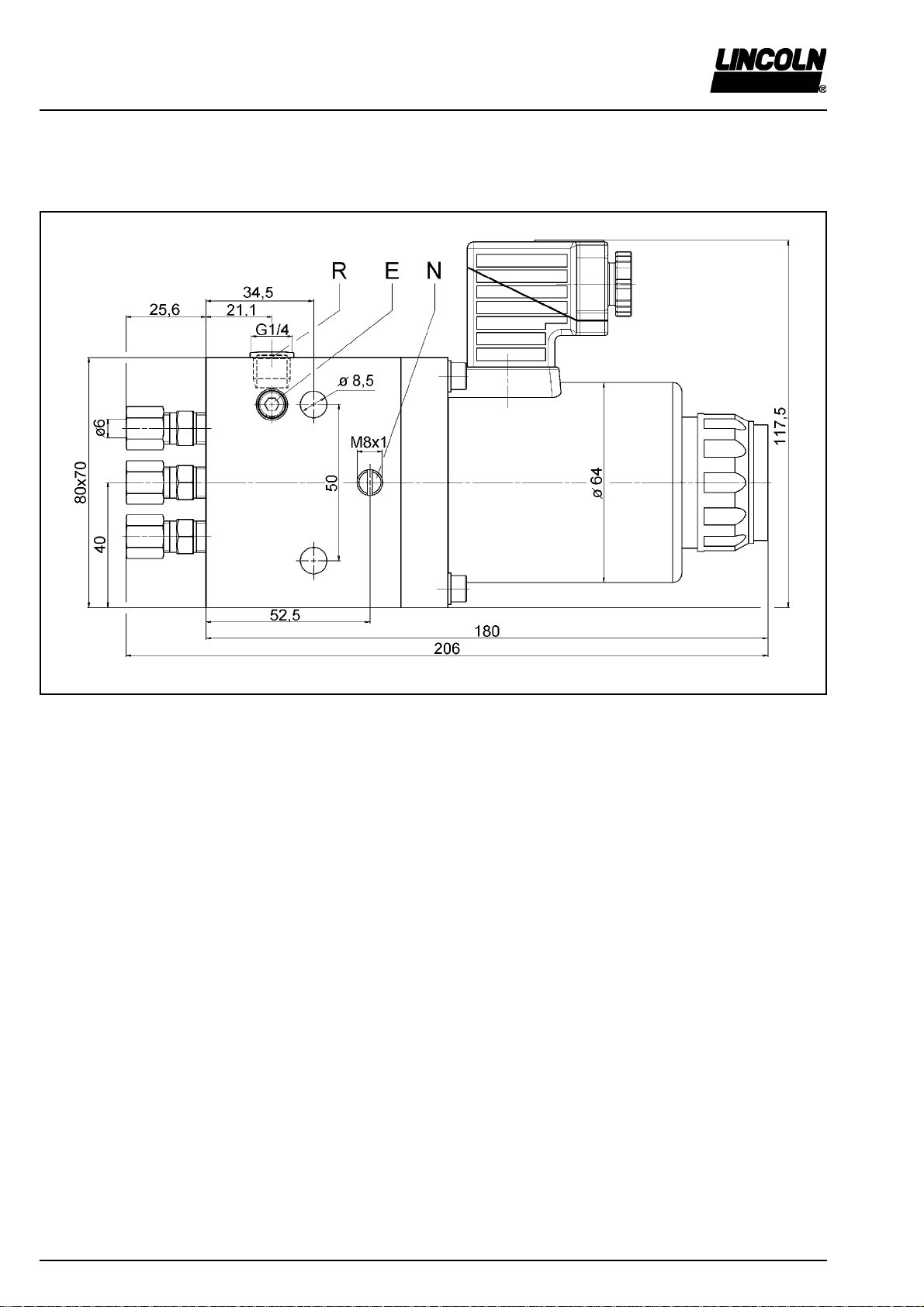
* Unscrew the venting screw (E, Fig. 11) until oil emerges.
Then re-tighten the venting screw.
* Let the pump run until all connected nozzles operate
properly.
Operation
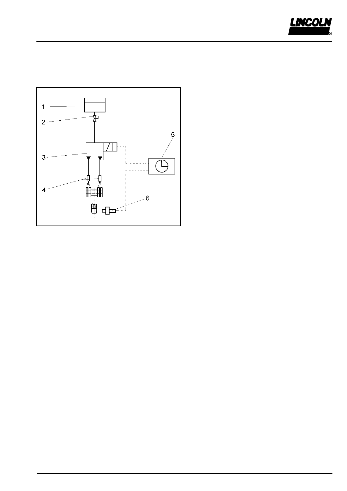
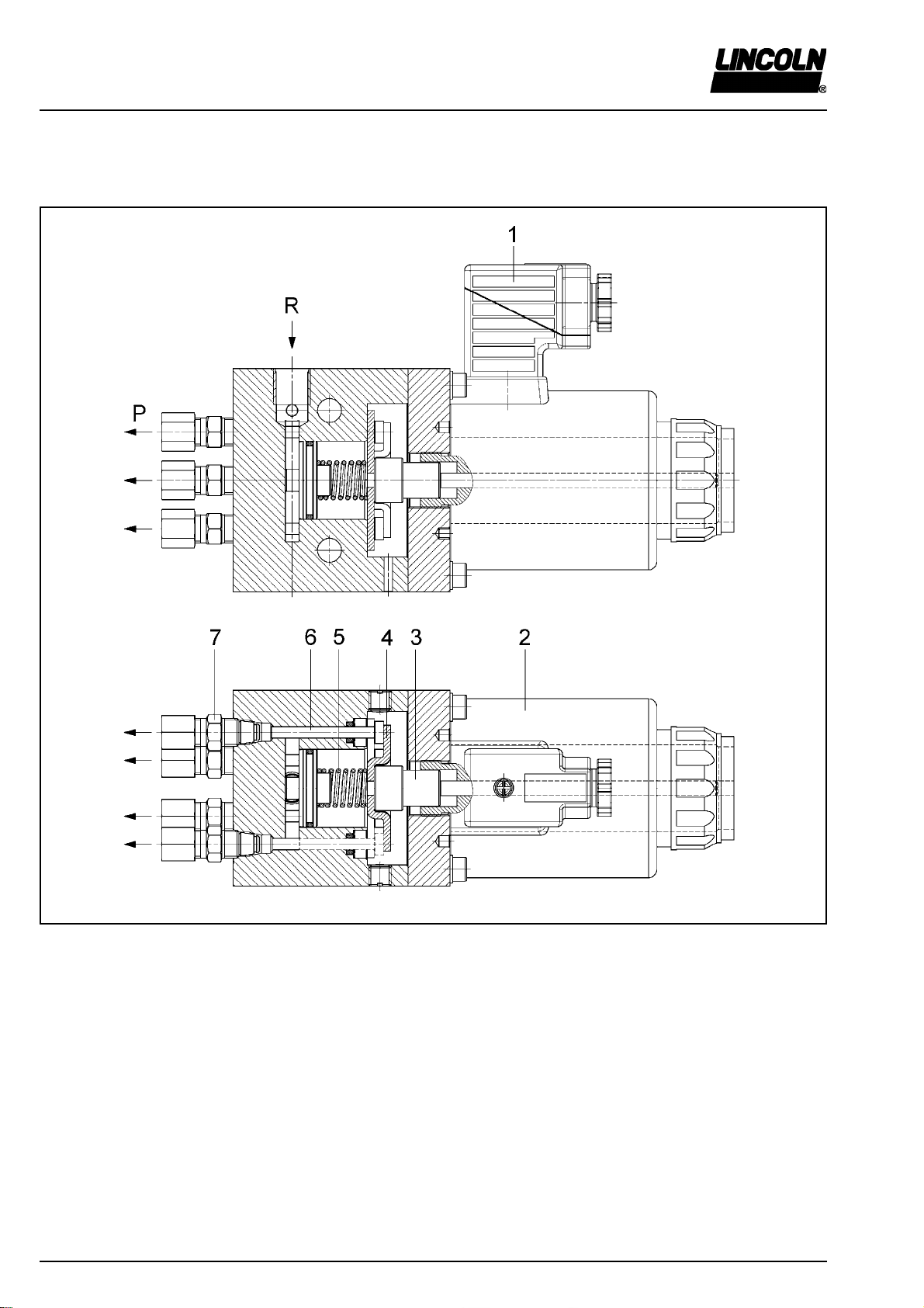
• The armature of the electric solenoid (2, Fig. 2) receives
an electrical pulse (energizing) from the proximity switch
(6, Fig. 1). It contacts the piston support (4, Fig. 2) via a
tappet (3). The piston support causes the pistons (6) to
move.
ErectionandInstallation
• even, solid and vibration-free installation surface
• protected from dust and dirt
• safe from atmospheric influences
• Installation position: horizontal, venting screw
to the left or to the right
• Oil supply: free oil supply from the
reservoir
Tightening torque of the faste-
ning screws 15 Nm 10%
Max. length of tube line
to the nozzles:
Output 60 mm³: steel tube 6 m
plastic tube 3 m
Output 30 mm³: steel tube 3 m
plastic tube 1.5 m
Specifications of the installation site Electrical connection
Before connecting the device,
disconnect the system from the
power supply.
The installation and connection of electric devices must
be carried out only by qualified electrician personnel!
Observe the relevant rules of technology and the respec-
tive work protection legislation (directives, standards).
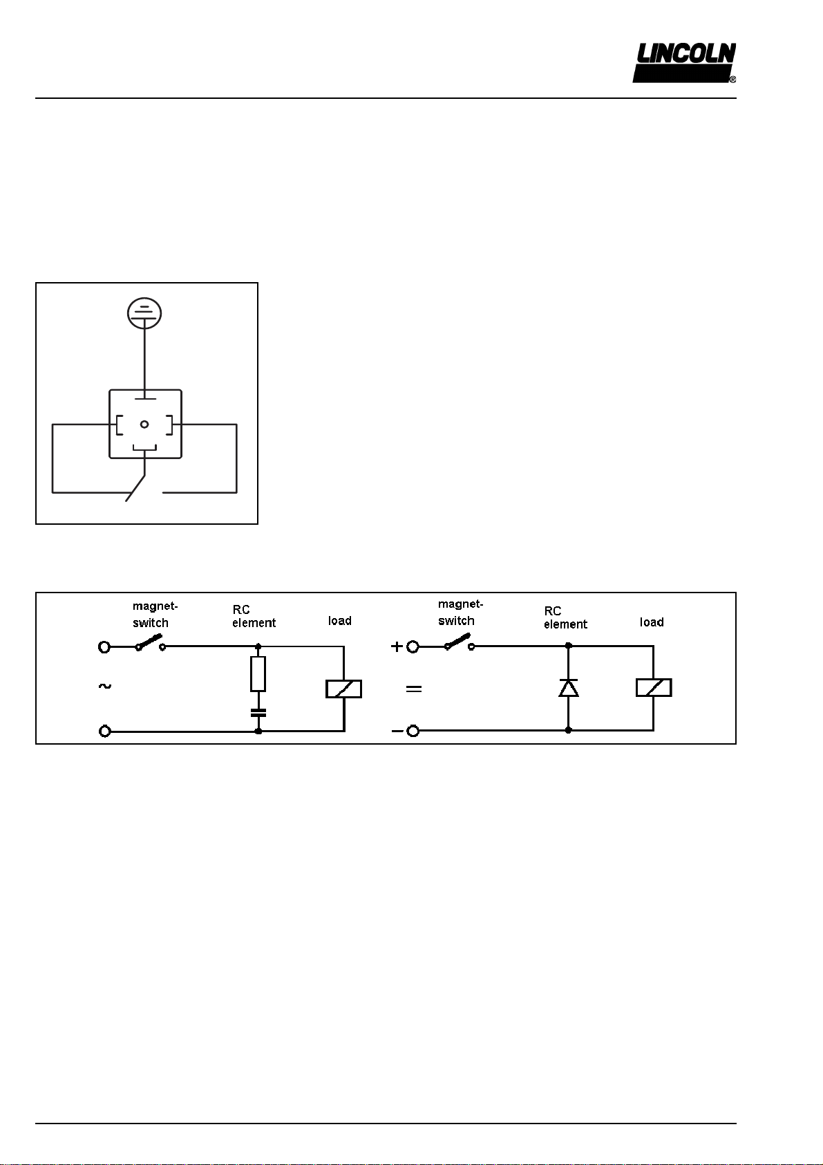
Electric connection of the electrical solenoid
• in accordance with the electrical wiring diagram and the
switching diagram
Electric connection of the proximity switch
• in accordance with the electrical wiring diagram and the
switching diagram
OperatingInstructions
Maintenance and Repair
Before undertaking any repair on the
pump:
*Disconnect the system from the
power supply and make sure that it
cannot be restarted inadvertently
* Close the shut-off valve in the oil
supply line
* Reduce the pump and system
pressure to zero. Danger due to
splashing oil.
•Repair work may be carried out only by qualified
personnel using original Lincoln spare parts.
• Provided that the pump dispenses only clean oil, it does
not need any particular maintenance.
• The piston of each pump element lies directly in the oil
being dispensed and is therefore lubricated automatical-
ly.
• The pistons eject a dosed quantity of oil to the pressure
connection (P). The return stroke of the pump pistons
and that of the armature are spring activated. During the
return stroke the pistons suck fresh oil from the storage
chamber. The pump is ready for the next lubrication
pulse.
• A proximity switch (optional version) monitors the operati-
on of the pump.