Australian Monitor
Installation 11
the speaker lead the greater the losses will be,
resulting in reduced power and less damping at the
load. We recommend using a heavy duty two core
2
flex(fourcoreflexifbi-amping)10to12gauge(2mm
2
to2.5mm or50/0.25orequivalent)asaminimum.
Binding Post Outputs
When terminating to the 4 mm binding post (banana
jack) output connectors, banana plugs or bare wires
can be used. The red terminal is positive and the
blackterminalisnegative(ground).
If running in BRIDGE mode, only the red binding
posts are used. Channel A provides the positive
output to the load and channel B provides the
negativeoutputtotheload.
Speaker Outputs
When using the 4 pole speaker connector for
speaker output, use only the mating 4 pole in-line
connector. This connector is designed so that both
channelscanbefedfromasingleconnector.
Two speaker connectors are provided on the
amplifier.
The "Channel A" speaker connector actually carries
both channel A & channel B outputs (see Figure 4:
SpeakerConnectorWiringDiagrams).
The "Channel B" speaker connector carries the
ChannelBoutputonly.
This arrangement allows you the option of
connecting to the outputs separately or together.
Connecting through a single connector has the
advantage of minimising connections, preserving
phasing and simplified channel allocation, which is
particularly important when bi-amping or in bridge
mode.
IMPORTANT
Do not overload your amplifier by connecting the
channelBoutputtwice!
Channel A is used as the “dominant” channel and
when sourcing a dual output from Channel A the
followingstandardshouldbeused:
ChannelA=LeftorLowFrequencies.
ChannelB=RightorHighFrequencies.
Wheninbridgemode:
Pin1+=BridgeOutputPositive
Pin2+=BridgeOutputNegative.
Figure4.Speaker ConnectorWiringDiagram
3. Installation
Power Requirements
Power consumption for your model of the Synergy
Series amplifier is indicated on the rear panel for
maximumoutput.
Ensure that your mains voltage is the same as the
rearpanelmainsvoltagemarker(+/-10%).
Mounting
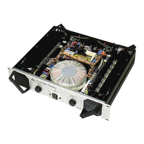
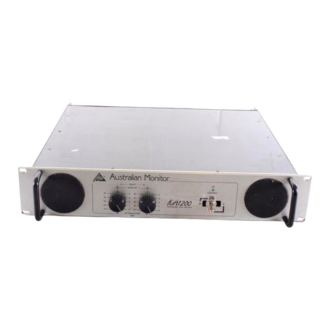
Your amplifier is designed for standard 19" rack
mounting and occupies 2 EIA rack units (3.5"). The
mountingcentresare:
Vertical: 3.0"(76.2mm)
Horizontal:18.2"(461.2mm)to18.7"(473.8mm).
The slots in the mounting flange will accept bolt
diametersupto1/4"(6.35mm).
We recommend that you provide additional support
for the amplifier, especially if road use is planned, as
the weight can bend some racks otherwise. This
supportcanbeprovidedbysecureshelving,support
railsorarearrackmountingstriptomatchupwiththe
rear rack mount ears provided on your Synergy Series
amplifier.
Cooling
Eachchannelof your SynergySeriesamplifieris cooled
by an axial fan which draws cool air from the front of
theunitand expelstheheatedair fromtherearof the
unit. These units offer two speed fans which run at
half speed, switching to full speed when the internal
0 0
heatsinktemperatureexceeds60C(128 F).
An unrestricted airflow into and out from the unit
must be provided. Any restriction of the air flow will
cause heat to build up within the unit and possibly
forcetheunitintoitsthermalshutdownmode.
If the units are to be operated in an environment
where the airflow is restricted such as sealed racks,
thecoolingshouldbe supplementedbyextracooling
fans to evacuate the heated air and aid the flow of
coolairthroughtheunit.
Input Wiring
IMPORTANT
Do not directly connect pin 1 on the amplifier’s input
or strapping XLR, to the amplifier’s chassis, speaker
groundorpowerground!
NOTE
Input signal ground is not to be used as a safety
ground(earth).
The input to your amplifier is a balanced 3-pin
system and requires all three pins to be connected.
Only high quality twin-core shielded cable should be
used.
When wiring for a balanced source the connector
goingtotheinputofyouramplifiershouldbewiredas
follows:
Pin1=GROUND/SHIELD.
Pin2=HOT(InPhase-noninverting).
Pin3=COLD(ReversePhase-inverting).
When wiring from an unbalanced source you must
ensurethatpin3isconnectedtopin1(inputground),
either by linking the pins in the input connector or by
thesourceequipment'soutputwiring.
Whenwiringforanunbalancedsource:
Pin1=GROUND/SHIELD
Pin2=HOT(inphasewiththeamplifier’soutput),
Pin3=GROUND/SHIELD(joinstopin1).
NOTE:
In-line XLR connectors often have a termination lug
thatconnectsdirectlytothechassisoftheconnector.
Donotlinkthislugtopin1attheamplifier’sinputasit
will defeat the amplifier’s input grounding scheme.
Thislugisoften referredtoasa"drain”andisusedto
provide a termination to the chassis for shielding
purposes when a floating signal ground is required
between the source and destination, or when
disconnecting the signal ground is required to
reduce earth loop noise, or noise induced into signal
groundsfromstraymagneticfields.
Output Wiring
Whenwiring toyourspeakersalwaysusethelargest
gauge wire your connector will accept. The longer
10 Installation
