Page 3
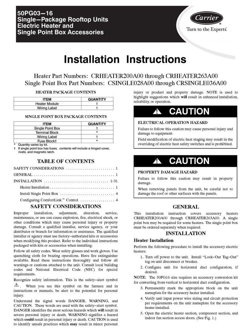
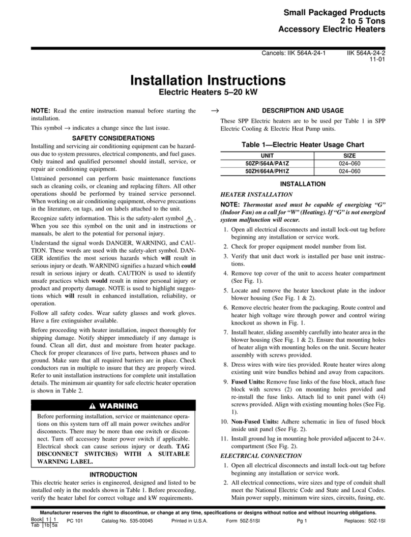
9. Install power wiring and connect to power block or circuit
breakers. In 12, 15 or 20kW models two power circuits
may be used to reduce wiring and breaker costs as in
Figure 7a. If a single circuit supply is desired, install the
optional single circuit accessory kit, as shown in Figure 7b,
that can be obtained from your Carrier distributor.
10. Check unit CFM of Table 1 and ensure airflow setting is
above minimum airflow rating for the electric heat model
from Table 2. Low speed blower not allowed with
electric heat.
11. Check staging jumpers for the application. Typically only
5 kW (factory setting on all models except 10kW on 20kW
models) is needed for first stage electric (W1) to minimize
electric demand. This staging can be adjusted by moving
the staging jumpers as shown in Figure 8.
12. Mark the appropriate box of the electric heat model
installed on the additional serial plate on the exterior of the
unit.
13. Turn on the power to the unit and the auxiliary electric
heat.
Auxiliary Electric Heat Start-up
14. Run thermostat to emergency heat mode (or jumper t-stat
input R to W) and setpoint to high setting. ‘Touch-jumper'
the test pins of the CXM or DXM into test mode to reduce
time delays. Unit will require 15-20 seconds before
engaging emergency heat mode stage 1 (W1) and then
another 15-20 seconds to engage stage 2 (W2) when in
‘Test mode’. Verify proper electric heat operation.
NO
Com ER1
NO
Com ER2
NO
Com ER3
NO
Com ER4
123
Tan
Ora
Factory Staging
(see Table 2)
Low Voltage Connector
(from Unit Control Board)
Genesis Electric
Heat Relay Board P1P2
24V
W1
W2
4
Staging Example on a 15kW unit W1 (first stage) has
5kW (‘ER1’ 5kW & ‘ER4’ 0kW) and W2 (second stage)
will have 10kW (‘ER2 & 3’ 5kW each)
1234
Tan
Ora
P2
Side View as seen in Control Box
P1
Figure 8. Staging Jumpers
Table 1. GT-G PSC Blower Performance Table
GT-G Electric
Heat Relay Board
GT-G
Series Fan Airflow (cfm) at External Static Pressure (in. wg)
0.05 0.10 0.15 0.20 0.25 0.30 0.35 0.40 0.45 0.50 0.60 0.70 0.80 0.90 1.00
50YCG Future Product - Data Not Available
50YCG Future Product - Data Not Available
H 781 771 764 757 748 740 718 697 665 638 610 - - - -
50YCG M 739 719 710 702 688 675 658 641 619 598 - - - - -
L* 626 613 605 597 589 581 566 551 531 512 - - - - -
H 781 771 764 757 748 740 718 697 665 638 610 - - - -
50YCG M 739 719 710 702 688 675 658 641 619 598 - - - - -
L* 626 613 605 597 589 581 566 551 531 512 - - - - -
H 1066 1038 1010 983 954 926 900 874 838 803 707 - - - -
50YCG M 902 886 870 854 831 809 782 756 726 702 - - - - -
L* 797 779 761 738 726 709 683 657 634 606 - - - - -
H 1173 1152 1125 1104 1081 1058 1033 1007 984 955 841 - - - -
50YCG M 1085 1061 1037 1013 975 938 916 894 864 830 - - - - -
L* 939 924 909 894 871 853 827 802 779 752 - - - -
H 1358 1330 1291 1258 1225 1198 1162 1132 1094 1057 965 858 - - -
50YCG M 1216 1193 1166 1143 1112 1082 1050 1023 982 941 - - - - -
L* 1069 1059 1049 1039 1021 999 975 952 925 899 - - - - -
H - - 1780 1700 1622 1612 1580 1544 1491 1434 1343 1211 - - -
50YCG M 1546 1524 1502 1480 1450 1426 1396 1371 1333 1294 - - - - -
L* 1217 1205 1193 1181 1168 1156 1128 1100 1063 1031 - - - - -
H - - 1893 1851 1807 1768 1718 1664 1630 1596 1454 1322 1195 - -
50YCG M 1744 1699 1664 1624 1578 1532 1498 1468 1419 1376 - - - - -
L* 1362 1336 1314 1298 1275 1252 1219 1187 1152 1112 - - - - -
H - - - - 2222 2197 2167 2137 2106 2076 2019 1941 1839 1705 1641
50YCG M 2135 2113 2090 2068 2045 2022 2004 1981 1950 1924 1871 1869 - - -
L* 1909 1890 1876 1862 1841 1825 1803 1787 1762 1733 - - - - -
H - - - - 2501 2477 2439 2400 2370 2345 2275 2205 2061 1921 1779
50YCG M 2465 2432 2403 2380 2353 2331 2304 2278 2250 2223 2158 2076 - - -
L* 2132 2117 2107 2092 2069 2052 2031 2001 1976 1940 - - - - -
Includes allowance for wet coil and clean factory-installed filter
Factory settings are indicated in bold print
(-) operation not recommended
* Electric Heat operation not allowed with blower motor set at low speed
Model Snd
