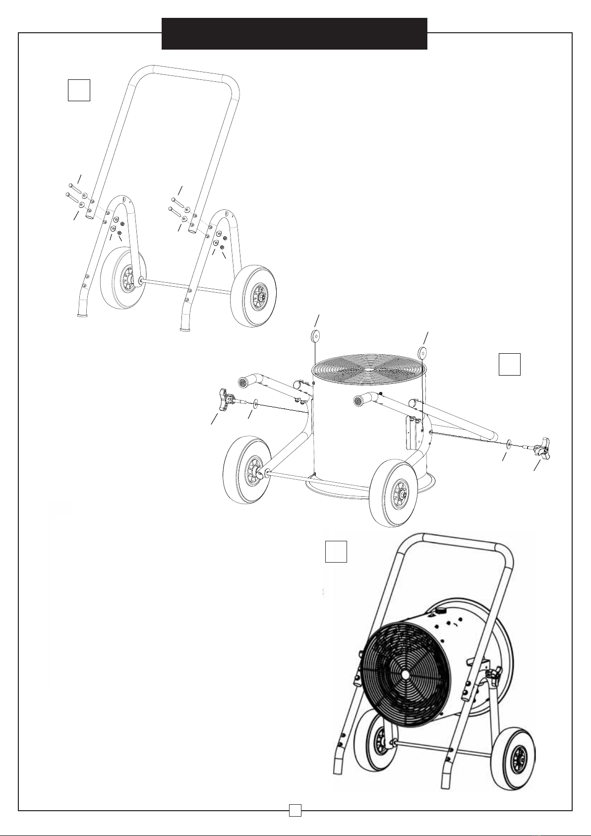
Instrucciones de Ensamblaje
2
Calentador De Aire Eléctrico
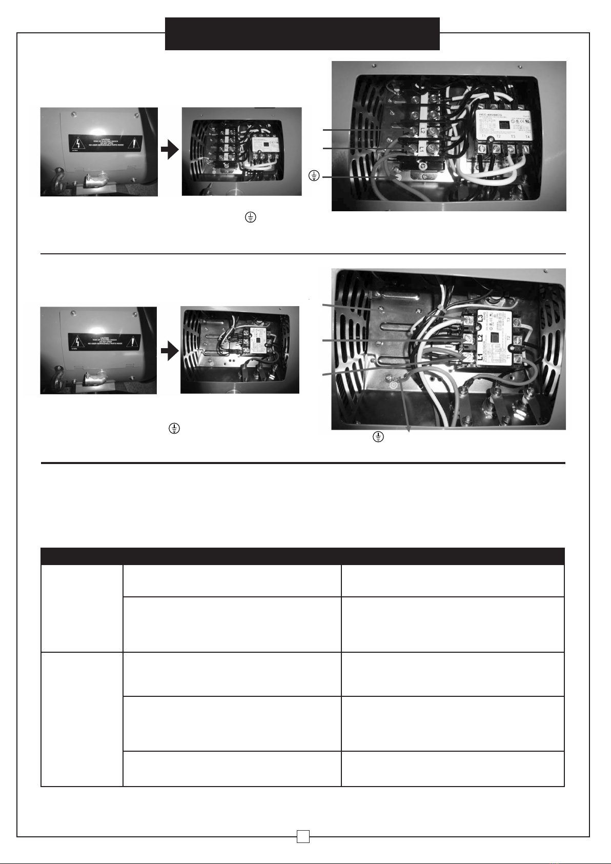
NOTA: este producto debe ser instalado por un electricista
certificado de conformidad con las normativas locales.
6. Los rastros de humo u olor cuando se inicia la unidad indican
que pequeñas cantidades de aceite se filtraron de la resistencia
para calentamiento durante la fabricación. El aceite se evaporará
rápidamente y no debe volver a ocurrir. Asegúrese de ubicar el
aparato en un área bien ventilada durante la instalación. Es normal
que la unidad emita sonidos cuando se enciende por primera vez.
7. Por favor, siga estas precauciones básicas cuando utilice
aparatos eléctricos para reducir el riesgo de incendio, descarga
eléctrica y daños personales o materiales:
1. Lea todas las instrucciones antes de usar el calentador.
2. La unidad se calentará cuando esté en uso. Evite que su piel entre en
contacto con superficies calientes para prevenir lesiones. Mantenga
materiales combustibles, como muebles, ropa de cama, prendas de
vestir, etc., por lo menos a 90 cm de distancia del calentador.
3. Precaución y supervisión Extreme es necesario cuando se usa
cualquier calentador cerca de niños o mascotas y cuando el
calentador se deje funcionando sin vigilancia.
4. Apague siempre el calentador cuando no esté en uso.
5. No utilice el calentador si la unidad no está funcionando correctamente,
se cayó o está dañada de alguna manera. Desconecte la corriente en
el panel de servicio y consulte a un electricista certificado para que
revise el calentador antes de volver a usarlo.
6. No utilice el calentador en exteriores
7. Para desconectar el calentador, corte la corriente en el panel principal
de desconexión.
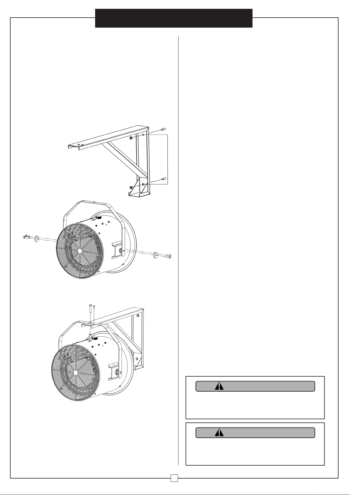
8.
Para instalar el calentador en el techo o la pared, no lo sitúe a menos de
2,4 m de altura desde el suelo y a menos de 30 cm para las superficies
adyacentes verticales o paredes. Mantenga la unidad al menos a 11,5
cm de la pared posterior (con o sin soporte de montaje de pared).
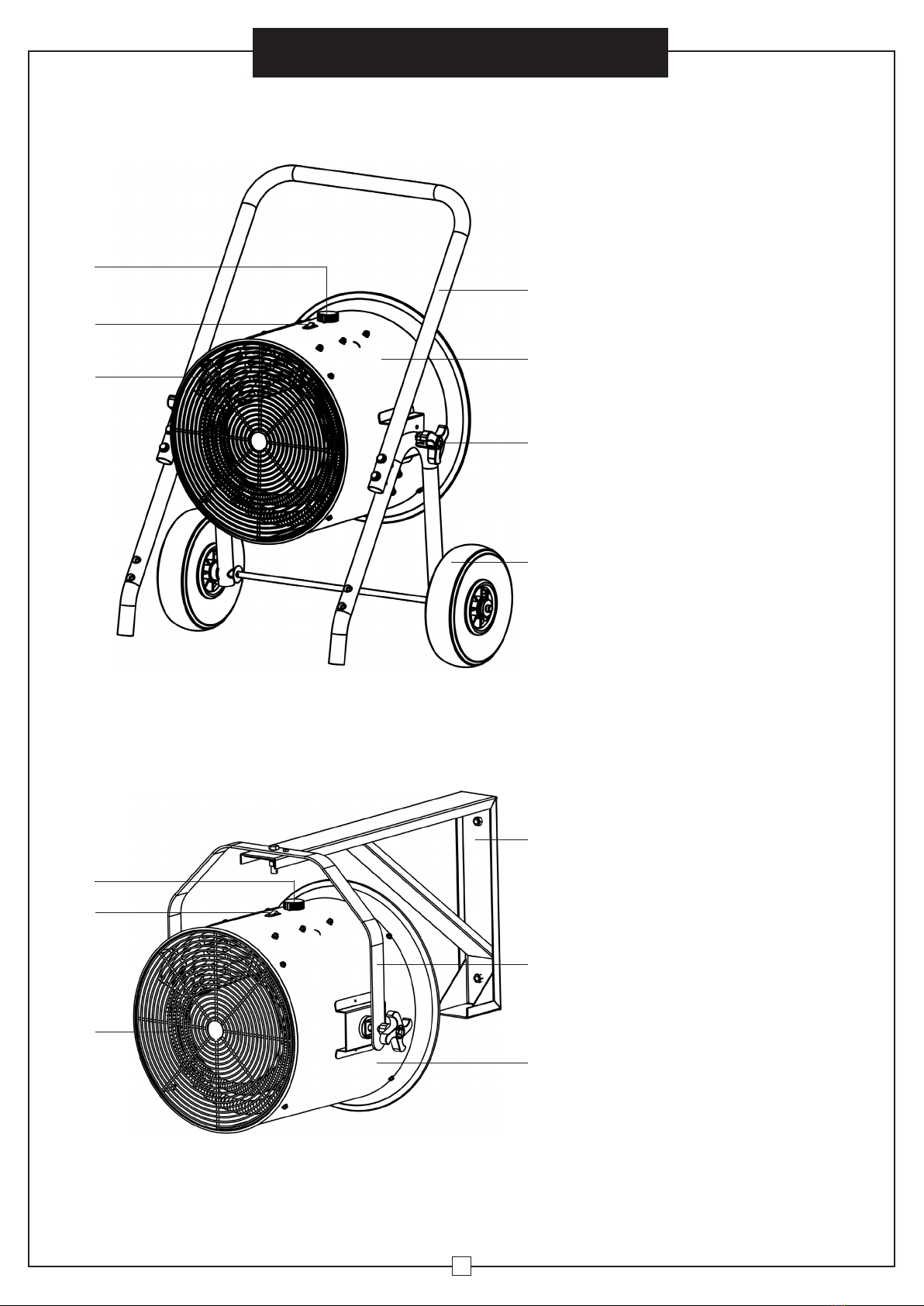
9. Cuando utilice una carretilla, asegúrese de que este sobre un terreno
plano. Mantenga por lo menos a 30 cm de cualquier superficie
adyacente vertical o paredes, y a 30 cm de la pared trasera.
10. No inserte, ni permita que entren, objetos extraños en las aberturas
de ventilación o escape, ya que podría provocar un incendio o
descarga eléctrica, o dañar el calentador.
11. Para evitar un posible incendio, no bloquee de ninguna manera las
entradas o salidas de aire.
12. Las unidades contienen equipos calientes y de formación de arcos
eléctricos internos. Para reducir el riesgo de incendio, no utilice el
calentador en zonas donde se use o almacene gasolina, pintura, o
vapores y líquidos inflamables.
13. Utilice el calentador sólo como se describe en este manual.
Cualquier otro uso no recomendado por el fabricante puede
provocar incendios, descargas eléctricas o lesiones.
14. Este calentador no está diseñado para su uso en baños, áreas de
lavandería y recintos similares cerrados. Nunca ubique el calentador
cerca del agua.
Para el modelo 653558 sólo
15. Enchufe el calentador directamente en un toma/receptáculo de pared.
Evite emplear extensiones o regletas debido al sobrecalentamiento
y el riesgo de incendio.
INSTRUCCIONES DE IMPORTANCIA
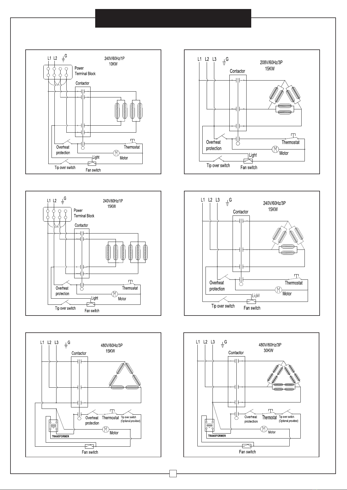
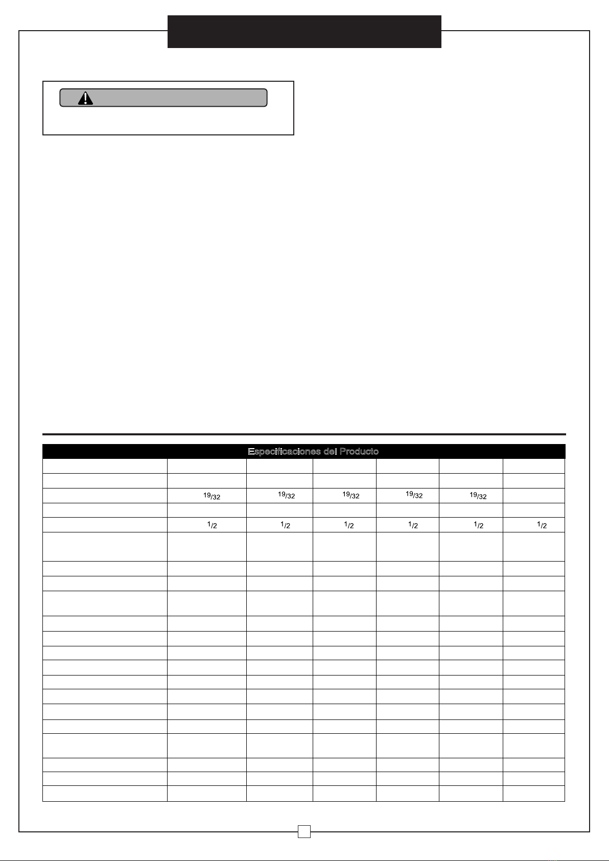
Especificaciones del Producto
Modelo 653558 653559 653560 653561 653562 246067
Largo Pulgadas
2119/32 2119/32 2119/32 2119/32 2119/32 22
Ancho Pulgadas
28 28 28 28 28 28
Alto Pulgadas
381/2 381/2 381/2 381/2 381/2 381/2
Tamaño
Cable para
NEMA 6-50P Enchufe
con Cable L
(viene con la unidad)
6/4 SO, SOOW 4/3 SO, SOOW 6/4 SO, SOOW 12/4 SO, SOOW 6/4 SO, SOOW
Peso Neto Lbs.
63 60 60 60 60 83
Color Naranja
Orange Orange Orange Orange Orange
Estructura
Acero Laminado
en Frío
Acero Laminado
en Frío
Acero Laminado
en Frío
Acero Laminado
en Frío
Acero Laminado
en Frío
Acero Laminado
en Frío
Altura Btu
34,120 51,180 51,180 51,180 51,180 102,389
Altura Cfm
1584 1584 1584 1584 1584 1966
Alza Temperatura °F
105 122 122 122 122 208
Voltaje
240 208 240 240 480 480
Fase
131333
Amps
41.7 41.7 62.5 36.1 18.1 36
Vatios
10,000 15,000 15,000 15,000 15,000 30,000
Kilovatios
10 15 15 15 15 30
Interruptor de circuito
nominal de amperios
50A 50A 75A 45A 25A 45A
Sécurité Tip-Switch
Oui Oui Oui Oui Non Non
Años Garantía
Limitada
111111
Certificación
CSA,CSAus CSA,CSAus CSA,CSAus CSA,CSAus CSA,CSAus CSA,CSAus
ADVERTENCIA
Por favor, lea completamente las instrucciones
antes de usar el calentador.