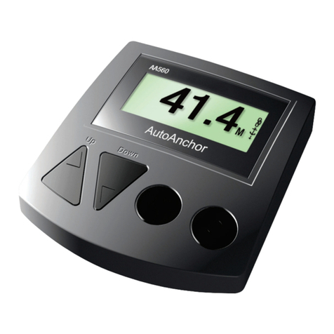
Auto Anchor 560 Instruction manual

IMPORTANT INFORMATION
READ BEFORE INSTALLING OR USING THE AUTOANCHOR
1
This User Guide is intended as a quick reference for day to day use of
the AA560. It must be read in conjunction with the Owner’s Manual. The
Owner’s Manual has installation, set up and testing instructions plus
information relating to troubleshooting and maintenance.
The AutoAnchor manufacturer and supplier accept no liability for personal injury or
property damage resulting from failure to follow the installation and operating instructions
or the use of the AutoAnchor in a way that may cause accidents or damage or that may
violate the law.
USER PRECAUTIONS
It is the owner’s sole responsibility to ensure the AutoAnchor is installed, used and
maintained in a manner that will not cause accidents, personal injury or property damage.
When using the AutoAnchor the operator must use safe boating practices and safe
windlass/winch and anchoring operation
• use the windlass/winch strictly according to the manufacturer’s instructions;
• only persons who are fully aware of the correct use of the windlass/winch
should be allowed to use the AutoAnchor to control this equipment;
• the user must personally control and supervise all anchoring operations;
• the user must know the location of the main breaker or battery switch to
disconnect the windlass/winch from all power sources in the event of an
emergency;
• the windlass/winch power supply must be turned off when the equipment is not in
use;
• there must be an alternative method available to operate the windlass/winch.
When Controlling a Windlass/Winch
• maintain a clear view of the windlass/winch, rode and/or anchor during operation;
• always ensure the anchor is fully docked and secured before moving the boat.
SET UP AND TESTING
Before use the AutoAnchor must be correctly set up for the equipment it is to control
and then tested in a safe environment. The AutoAnchor will not count correctly if the
windlass selection is wrong or the windlass is not standard (eg it is installed with a different
chainwheel or motor).
Required for all sensors other than a motor driven reed sensor. This screen automatically
displays on first use or if Factory Defaults are loaded, the sensor is reset or there has been
a loss of sensor signal. Refer to page 21 in the Owner’s Manual.
PLUG & PLAY SENSOR TUNING

2
OPERATION
AA560 BUTTONS
Lock
The AutoAnchor is fitted with a lock to help protect against unintentional windlass
operation.
Hold the Mode button for 2 seconds to unlock.
Unlocked
Locked
The lock automatically resets 5 minutes after the AutoAnchor was last operated or when
the AutoAnchor is turned off. You can also reset the lock by holding down the button
until the key is displayed in the top right corner.
Note: Some operators prefer to swap the Up/Down buttons as follows:
Up = Out and Down = In. See the instructions on page 18 of the Owner’s Manual.
In an emergency shut off the
power to the windlass using
the isolating/breaker switch.
DownUp Auto ON/OFF
Sensor Pulse Indicator
& Windlass Direction
Standard AA
Operation
Functions
Hold 2 sec
to Turn Off
Hold 2 sec
to Unlock
Status bar
INFORMATION DISPLAYED DURING OPERATION
The length of rode deployed in feet, metres or fathoms.
The direction the anchor is moving.
The type of rode being deployed (chain or rope).
Windlass speed.
Settings and measurements are saved if the unit is turned off or the battery fails.
Counting continues if the windlass is operated by another control eg foot switches.
•
•
•
•15 u
u

3
AUTOMATIC AND MANUAL OPERATION
Keep your finger on the button to deploy the anchor manually or use the automatic function
for hands free anchor deployment and retrieval. See the instructions for both options below.
MANUAL OPERATION
Deploy and Retrieve the Anchor Using Manual Operation.
Turn the AutoAnchor on.
Clear the safety lock.
Hold down the up or down button to deploy or retrieve the anchor. Releasing the
button stops the windlass operation.
Ensure the anchor is fully docked and secured before moving the boat.
DOCKING ALARM: During retrieval the windlass will stop and the
AutoAnchor beeps to warn the operator the anchor is at the preset
docking distance. Press and hold the button to continue retrieval.
Extra care must be taken at this stage of retrieval.
Use the Automatic Function to:
Preset the length of rode for deployment.
Have hands-free operation of the windlass.
Retrieve the anchor automatically to the preset docking distance.
Note: For rope/chain counting, if the sensor or load sensing wires are
not installed correctly the automatic function will not operate. An
Installation warning message will display on the screen. The windlass
can still be operated using manual operation but on retrieval the displaybut on retrieval the display
may be incorrect because it cannot allow for the stretch in the rope.
•
•
•
AUTOMATIC OPERATION
WARNING: There is an inherent risk when using any automatic function
on a boat. If you choose to use the AutoAnchor automatic functions, you
must still control and supervise all windlass and anchoring operation.
For an accurate reading always ensure the AutoAnchor display reads 0.0 before
deploying the anchor.

4
Enable Automatic Operation
A “rode to be released” value must be entered to use automatic operation.
Safety Override
Press any button on the AutoAnchor to stop the windlass during automatic release or
retrieval. In an emergency shut off the power to the windlass using the isolating/
breaker switch.
Deploy the Anchor Using Automatic Operation
Turn the AutoAnchor on.
Clear the safety lock.
Press the Mode button to select Auto. The screen
displays the current length for Auto release.
If this setting is correct. Press and release the down button to
deploy the anchor.
To Change the setting:
Press the Mode button again to select Set auto.
Enter the value.
Save and return to Auto.
The windlass will stop and the AutoAnchor will beep when
the preset length of rode has been released. The screen
will display “Auto target reached”.
To Set A Rode to be Released Value
Turn the AutoAnchor on.
Clear the safety lock.
Press the Mode button twice to enter Set auto.
Scroll up or down to change the value.
Save ready to deploy. Press twice to return to start screen.
To disable the automatic operation: Set the rode to be released
value to Off.
Retrieve the Anchor Using Automatic Operation
Turn the AutoAnchor on.
Clear the safety lock.
Press the Mode button to Select Auto.
Press and release the Up button to retrieve the anchor.
The windlass will stop and the AutoAnchor will beep when the
docking distance is reached. The screen will display
Docking distance.
Press the Up button to complete retrieval of the anchor.
The AutoAnchor will beep during this process.
Ensure the anchor is fully docked and secured before moving the boat.

To Check Logs
The AutoAnchor must be turned on.
Press to access the Menu.
Select Logs.
Return to the menu.
Exit and return to start screen.
Logs are cleared using the Factory Default Settings. See page 14 in the Owner’s Manual.
Resetting the Factory Defaults clears all logs and calibrations.
To Adjust Backlight
The AutoAnchor must be turned on. It is best to change this setting in low light.
Press to access the Menu.
Select Backlight.
Change the Backlighting level.
Save and return to the menu.
Exit and return to start screen.
OTHER OPERATION SETTINGS
Press to access the menu when the AutoAnchor is turned on.
To Clear to Zero
The AutoAnchor must be turned on.
Press to access the Menu.
Select clear to zero.
Select No/Yes.
Yes - return to start screen.
No - return to the menu, then press again
to return to the start screen.
9
10742
112
Clear to zero
Logs
Backlight
Reset sensor
Reset sensor
To Reset Sensor
The AutoAnchor must be turned on.
Press to access the Menu.
Select Reset sensor.
Select No/Yes.
Save and return to the menu.
Exit and return to start screen.
Deploy the anchor to tune the sensor.
See page 21 in the Owner’s Manual.
Reset sensor
Reset sensor
5

$$7528%/(6+227,1**8,'(
The AutoAnchor is not faulty if these messages display. The diagnostics help with troubleshooting the sensor and wiring. These messages display briefly during opera-
tion and/or power up. A beep will sound and after 3 seconds the message will be cleared. The count will not be accurate until the cause of the error is fixed. After
the windlass is retrieved and the error is fixed reset the AA150 by holding down one of the buttons to zero the display.
Use the table below to help identify a problem and provide a possible solution. If you cannot resolve the problem, contact your supplier for further information.
Problem Possible Solution
Sn 1
Appears during operation.
The AA150 does not count and does
not display a sensor pulse.
Sn 2 (Rope/Chain Only)
Appears during operation. The AA150 will
count and will display a sensor pulse. The
count will not be accurate.
Sensor is too close to the magnet. Ensure the gap between the magnet and sensor is no less than 35 mm for a
10mm x 8 mm magnet and 30mm for an 8mm x 6 mm magnet). The count will not be accurate until the problem
is fixed. Fix the installation and reset the counter to zero.
Sn 3 (Rope/Chain Only)
Appears during retrieval when using a rope/
chain rode. The AA150 will count and will
display a sensor pulse. The count will not
be accurate.
The AA150 has failed to detect the change from rope to chain or there has been excessive rope slippage. Com-
plete retrieval and then reset the counter to zero. This message may also display if the chain is the wrong size for
the chainwheel.
Sn 4
Appears during AA150 power up.
AA150 will not count but it will
display a sensor pulse.
The orange wire to the Up solenoid is not connected. Fix the wire connection and reset the counter to zero.
Ld (Rope/Chain Only)
Appears during AA150 power up. The
AA150 will count and will display a
sensor pulse. The count will not be
accurate.
The load sensor wires are not connected to the motor. Fix the connection and reset the counter to zero.
Bottom Fit All-Chain Windlasses Top Fit Rope/Chain Windlasses
Magnet 6mm x 4mm Min 3mm Max 30mm N/A
Magnet 8mm x 6mm Min 3mm Max 44mm Min 30mm Max 44mm
Magnet 10mm x 8mm Min 3mm Max 50mm Min 35mm Max 50mm
If using a reed switch sensor, the gap must be between a minimum of 3mm and a maximum of 5mm.
Note: If the installation uses a black all-chain sensor (Part No: 9008) the gap must be between a minimum
of 3mm and a maximum of 8mm and the south pole of the magnet must face the sensor.
AA150 counts when the windlass is not
turning or counts erratically displaying a
large number eg 888.
The count pauses during retrieval. This is not a fault. The rode is changing from rope to chain.
The sensor could be damaged, incorrect cable may be fitted, or the AA150 may have been subject to external
interference - RF or electrical. Check that the sensor cable is not damaged and that the cable fitted is as specified
in the instructions. Check for external interference on the boat eg damaged or loose RF cables or aerials or other
instruments that may not be working correctly or have been damaged by electrical interference including lightning.
No signal from the sensor to the AA150. Either there is no magnet, the gap between the magnet and sensor is too
big or the sensor signal is out of tune because of testing during installation. Try resetting the AA150 by running
the windlass up and down for 10-15 seconds. If the message still appears check the magnet and the gap and align-
ment between the magnet and sensor. Check sensor wiring and installation and check for damage to the sensor
and magnet. When fixed reset the AA150 as above. For manual reset, clear the counter to zero twice. To clear
to zero press and hold any key. The AA150 will beep and clear within 4 seconds. rE will be displayed during the
second clearing indicating the reset is okay.

AA500C TROUBLESHOOTING
Problem Possible Solution
1. AutoAnchor 500C will
not turn on.
Check battery is connected and has correct polarity. Check battery has sufficient voltage. See page 13 and note 3 below. Check fuses are working.
2. AutoAnchor 500C
does not operate the
windlass either up or
down.
Check Calibration Item 3 is not set to zero. Check the “Chain to be Released” is not set to zero (Refer to page 10). Check if the safety lock is on.
Check battery has sufficient voltage. See page 13 and also note 3 below.
The AutoAnchor 500C has built in diagnostics to help with troubleshooting. The diagnostics help identify problems with the battery, the solenoid, the sensor and windlass rota-
tion. The diagnostics appear briefly when the AutoAnchor 500C is first switched on. If you have a problem, check for the diagnostic messages by switching the AutoAnchor 500C
off and then on again.
Battery has dropped below 6 volts. Check battery connections and charge. See also note 3 above.4. AutoAnchor 500C
turns itself off.
ELECTRONIC DIAGNOSTICS
Battery low - check the voltage output. (See the notes on page 13). If the battery is fully charged check the wiring - for loose connections and check
the cable size. The cable from the battery to the console unit and/or the solenoids may not be heavy enough. See the Cable Specifications on page
15.
3. AutoAnchor 500C will
not operate the windlass
and the LCD shows
BATT when the UP
or DOWN buttons are
pressed.
6. Solenoids click on
and off when the UP
or DOWN buttons are
pressed but the windlass
does not operate.
Either the yellow (down) and orange (up) solenoid wires are shorted together or the AutoAnchor 500C has a poor ground connection. Check the
wiring and ensure the solenoid wires are separated.
The solenoids could be exceeding the maximum 2.6 Amps. The AutoAnchor 500C is designed to turn off if this occurs. Contact your supplier for
further information. Also see note 3 above.
7. Screen shows SOL. Solenoids are not connected. Check wiring to solenoids or control box.
5. The windlass operates
for a short period and then
stops. The AutoAnchor
500C may turn off.
Use the table below to help identify a problem and provide a possible solution. If you cannot resolve the problem, contact your supplier for further information.
Definitions SOL = Solenoid, SENS = Sensor, BATT = Battery
12. AutoAnchor 500C
display shows “Eror”
The Up or Down button has pressure on it at the time the the unit is turned on. Clear the pressure from the button. Then turn the unit off.
Turn it on again to operate normally.
8. AutoAnchor 500C
will not count or shows
SENS and the windlass
stops during automatic
operation.
The sensor is not working properly. Check the calibration settings are correct. Check if the sensor is disconnected or damaged. Check
wiring from console to sensor for loose connections and check that it is the correct specified cable.(See below). Check the magnet and
sensor are aligned and the gap between them is correct. (See Installation Instructions). Check the magnet is not corroded. Check the
magnet is installed with the white(south) end facing the sensor.
9. AutoAnchor 500C
counts when the
windlass is not turning
or counts too much per
revolution or displays
an unusually large
number.
The sensor may be damaged or the sensor cable is not the specified type. See the Cable Specifications below.
10. AutoAnchor 500C
does not stop exactly at
the preset point.
This is not a fault - Stopping is accurate to +1 chainwheel revolution. The chainwheel may run on slightly with momentum.
This will occur during automatic operation if you try to release more chain than is on board. Check the setting for chain on board.
(Calibration Item 3).
11. The windlass stops
before the length of chain
specified is deployed.
Note: When the sensor
is operating correctly
the sensor (feet/metres)
indicator flashes every
time the magnet passes
the sensor.

Message/Problem Possible Solution
TheAA550 is not faulty if these messages are displayed. The diagnostics help identify problems with installation, the battery, the solenoid
and the sensor and windlass rotation. Some of the messages appear when you try to operate the AA550 but others only appear briefly when
the AA550 is turned on. Always check for the diagnostic messages by switching the AA550 off and then on again. Use the table below to
help identify a problem and provide a possible solution. If you cannot resolve the problem, contact your supplier for further information.
ELECTRONIC DIAGNOSTICS
Definitions SoL = Solenoid, SEN = Sensor, Lo Pr = Low Power
3. Lo Pr + a number
Displayed when the Up or
Down button is pressed. The
AA550 will not operate the
windlass.
Low power to the AA550. To check the voltage received by the AA550, turn the AA550 off, and press
and hold the Down button. The voltage will display on the LCD. Check the battery voltage output.
Check wiring for loose connections. Check the cable size. If the cable is the wrong size there may be
voltage drop between the battery and the AA550. See the cable specifications on page 2 and the minimum
voltages on page 7.
SEN and LoAd messages: When these messages are displayed the AA550 will operate the windlass up and down manually but the Auto
function will not work and the count will not be accurate.
6. SEN 1
Displayed briefly when the
AA550 is turned on and
when it is operated manually.
Auto does not work. No sen-
sor pulse.
1. LoAd
Displayed briefly when the
AA550 is turned on and
when it is operated manually.
The Auto function does not
work.
2. LoC
Displayed when a button is
pressed. The AA550 will
not operate.
7. SEN 2
Displayed briefly when the
AA550 is turned on and when
it is operated manually. Auto
does not work. No sensor
pulse.
8. SEN 3
Displayed when the AA550 is
operated manually. Auto does
not work. No sensor pulse.
The sensor wires are disconnected or the red and black sensor wires are shorted together. AA550 will
operate the windlass up and down but there will be no count displayed on the LCD. Check sensor wiring
and installation. When fixed reset the AA550 to zero twice. The anchor must be docked. To reset to zero
- press and hold the ON/OFF button. Release when the display shows 0.0.
The load sensor wires are not connected to the motor. Use the AA550 manually and check the load wire
connections. If using an all-chain rode check that the AA550 is calibrated correctly for all-chain. When
fixed reset the AA550 to zero. The anchor must be docked. To reset to zero - press and hold the ON/OFF
button. Release when the display shows 0.0. The count will not be correct until the problem is fixed.
The safety lock is on. Hold down the Mode button to release the safety lock and then operate as normal.
5. SEN
Displayed when attempting
to use the Auto function.
Use the AA550 up and down manually and check for the specific sensor error. SEN1 - SEN5. Refer to the
notes 6-10 below.
4. OFF
Displayed when attempting
to use the Auto function.
No setting has been entered for the rode to be released so the Auto function cannot operate. Enter a length
of rode for release and the system will operate normally. (Refer page 10 Operation Manual).
The black sensor wire is shorted to ground. AA550 will operate the windlass up and down but there will
be no count displayed on the LCD. Check sensor wiring and installation. When fixed reset the AA550
to zero twice. The anchor must be docked. To reset to zero - press and hold the ON/OFF button. Release
when the display shows 0.0.
No signal from the sensor to the AA550. Either there is no magnet, the gap between the magnet and sen-
sor is too big or the sensor signal is out of tune because of testing during installation. AA550 will operate
the windlass up and down but there will be no count displayed on the LCD. Try resetting the AA550 by
running the windlass up and down for 10-15 seconds. If the message still appears check the magnet and
the gap and alignment between the magnet and sensor. Check sensor wiring and installation and check for
damage to the sensor and magnet. When fixed reset the AA550 as above. To reset manually the anchor
must be docked and the AA550 reset to zero twice. To reset to zero - press and hold the ON/OFF button.
Release when the display shows 0.0.
AA550&AA560 Troubleshooting

17. The windlass does not stop
exactly at the preset point.This is not a fault. Stopping is accurate to +1 chainwheel revolution. The chainwheel may run on slightly
with momentum.
18. AA550 counts when the
windlass is not turning or
counts erratically displaying a
large number eg 8888.
The sensor could be damaged, incorrect cable may be fitted, or the AA550 may have been subject to ex-
ternal interference - RF or electrical. Check that the sensor cable is not damaged and that the cable fitted
is Beldon 9501 or equivalent, 2 core, tinned, copper, screened, as specified in the instructions. Check for
external interference on the boat eg damaged or loose RF cables or aerials or other instruments that may
not be working correctly or have been damaged by electrical interference including lightning.
19. AA550 beeps when it is
turned off or locked.
Anchor rode is running through the windlass. Check if the windlass is being operated using the deck
switches or a remote control. If not, check the windlass and anchor is secured.
20. The count pauses
during retrieval.
If the sensor indicator is pulsing this is not a fault. The rode is changing from rope to chain.
13. AA550 will not turn
on or turns off.
Check if the safety lock is on - the LCD will display LoC. Refer note 2 above.
Check voltages at the battery and the AA550. The LCD will display Lo Pr. Refer note 3 above.
Check wiring for loose connections to the solenoids. The LCD will display SoL Up or SoL dn if the
wires are disconnected. Refer note 12 above.
Check that the windlass is not already in operation using the deck switch or remote control.
Check the total rode on board (Calibration 3 - Operation Manual Pg 4) is not set to OFF.
14. AA550 will not
operate the windlass.
Check battery connections, polarity and voltage. The voltage to the AA550 can be checked by turning it
off and holding the Down button. The voltage is displayed on the LCD. See page 7 for minimum volt-
ages. Check fuses and wiring and for the Lo Pr diagnostic message. Refer note 3 above.
15. AA550 will operate the
windlass manually but Auto
function does not work
16. Windlass rotates down
when the Up button is
pressed and up when the
Down button is pressed.
Check the rode to be released is not set to zero. The LCD will display OFF. See note 4 above. Use the
AA550 manually and check for specific diagnostic messages SEN or LoAd (See notes 1 and 5-10 above).
The motor or solenoid wiring is reversed. Change the wiring and check the direction of the windlass
rotation.
12. SoL uP or SoL dn
Displayed briefly when the
AA550 is turned on. The
AA550 will not operate the
windlass.
SoL uP - The Up (orange) wire is not connected to the solenoid. SoL dn - The Down (yellow) wire is not
connected to the solenoid. These messages also appear if the up or down button is pressed on the AA550
when the windlass is already in operation using a deck switch. Diodes or interlock devices between the
AA550 and the solenoid will also cause these messages. The AA550 has internal diode protection. Exter-
nal diodes will cause the system to fail.
11. SoL oL
Displayed when the Up or
Down button is pressed. The
windlass may operate for a
short period and then stop.
The solenoids could be exceeding the maximum 4 Amps or a solenoid wire is shorted to ground. The
AA550 is designed to turn the solenoids off if these events occur. Check the solenoids and the wiring and
fix as necessary.
9. SEN 4
Displayed when the AA550
is operated manually. The
sensor indicator does pulse.
Auto does not work.
The sensor is too close if running rope/chain or the windlass has been run without rode.AA550 will oper-
ate the windlass up and down but the count will not be accurate. Try resetting the AA550 by running
the windlass up and down for 10-15 seconds. If the message still appears make sure you have the correct
calibration setting for the windlass and rode. Check the magnet and sensor are aligned, the sensor is in
the correct quartile and the gap between the sensor and magnet is correct. Check for loose wiring from
the sensor to the AA550. When fixed reset the AA550 as above. To reset manually, the anchor must be
docked and the AA550 reset to zero twice. To reset to zero - press and hold the ON/OFF button. Release
when the display shows 0.0. the display shows 0.0.
10. SEN 5
Displayed during retrieval.
The sensor indicator does
pulse. Auto does not work.
The AA550 has not detected the change from rope to chain. Use Manual Up to complete retrieval. The
count displayed will not be accurate. Check for rope slippage and that the rope and chain are the correct
size for the chainwheel. Check that the sensor is in the correct quartile. When fixed reset the AA550 to
zero. The anchor must be docked. To reset to zero - press and hold the ON/OFF button. Release when the
display shows 0.0.
&KHFNRXWWKHFROOHFWLRQRIDQFKRUVDQGGRFNLQJZHRIIHU
Other manuals for 560
2
Table of contents
Other Auto Anchor Remote Control manuals

