auto maskin Marine Pro RP 410 User manual

Manual# 1100272
Quick Installation Guide
RP 410
Remote Panel


Quick Installation Guide
P a g e | 1
Table of Content
Document Information ............................................................ 2
Content ............................................................................. 4
Installation ............................................................................. 5
Unwrapping ....................................................................... 5
Panel Installation ............................................................... 5
Network............................................................................. 6
Power-On .......................................................................... 7
Factory Startup Wizard ....................................................... 7
System Configuration......................................................... 8

P a g e | 2
Quick Installation Guide
Document Information
Valid Versions
This Quick Installation Guide is valid for the following
firmware releases.
Panel
Firmware
RP 410
1.4 –>
DCU 410/408
1.4 –>
Manual Revisions
Title:
Quick Installation Guide
Printed:
January 2017
Revision:
4
Copyrights and Trademarks
Copyright © Auto-Maskin AS, 2017
Information given in this document may change without
prior notice. This document should not be copied without
written permission from Auto-Maskin.
All trademarks acknowledged.
Quick Installation Guide
P a g e | 3
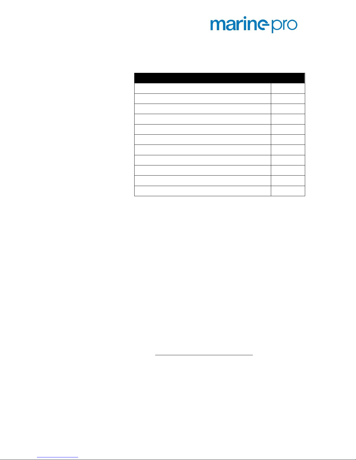
Ordering Information
The following parts are available in the Marine Pro range
Item
Part #
DCU 410 –Engine Control
1006450
DCU 408 –Engine Control
1006455
RIO 410 –I/O Expansion
1006453
RIO 425 –Generator Interface
1006409
SDU 410 –Safety Unit
1006451
RP 410 –Remote Panel
1006452
MK-14 –Relay Expansion
1121341
DCU 210 –Engine Control
1006481
DCU 208 –Engine Control
1006480
RP 210 –Remote Panel
1006482
IP Camera
1121258
About this manual
This manual has been published primarily for
professionals and qualified personnel. The user of this
material is assumed to have basic knowledge in marine
systems, and must be able to carry out related electrical
work.
Work on the low-voltage circuit should only be carried
out by qualified and experienced personnel. Installation
or work on the shore power equipment
shall only
be
carried out by electricians authorized to work with such
installations.
Responsibilities
It is the
sole responsibility of the installer
to ensure that
the installation work is carried out in a satisfactorily
manner, that it is operationally in good order, that the
approved material and accessories are used and that the
installation meet all applicable rules and regulations.

P a g e | 4
Quick Installation Guide
Note! Auto-Maskin continuously upgrades its products
and reserves the right to make changes and
improvements without prior notice.
All information in this manual is based upon information
at the time of printing.
For updated information, please contact your local
distributor.
Content
This Quick Installation Guide covers the basics of
successfully installing the RP 410 Remote Panel.
For the full RP 410 Installation Manual, please refer to the
Marine Pro section at www.auto-maskin.com.
This Guide covers the basics of installing the RP 410.

Quick Installation Guide
P a g e | 5
Installation
Unwrapping
Make sure the unit is not damaged in transport, and that
these parts are in the box:
The RP 410 Remote Panel
A bag of screws and nuts
Panel Installation
The RP 410 is intended as a remote command and
monitoring panel, and as such can be installed in the
engine control room or in the wheelhouse.
The RP 410 should be installed in suitable enclosure, and
it must have easy operator access.
Make an enclosure cutout of 307 x 183mm (W x
H).
Drill holes with Ø=3.5mm for the four fastening
screws.
Using the 3mm screws and nuts, securely fasten
the RP 410.

P a g e | 6
Quick Installation Guide
Network
In its simplest form, connect a
standard CAT5 ethernet cable
between a single DCU and the RP,
using the ethernet ports on the two.
Auto-Maskin recommend however, always installing an
ethernet switch in-between the two for these reasons:
Easy to connect a laptop to the
network
Easy to expand with more DCU and
RP panels
Does not matter if ethernet cable is
crossed or straight.
In the one-line diagram example above, multiple panels
and equipment is connected together with the switch.

Quick Installation Guide
P a g e | 7
Power-On
Connect the 24V supply
The supply is typically the ships redundant 24VDC supply.
Unplug the wire terminal block, and connect the 24V
supply wires as follows:
24V to terminal 1
0V to terminal 2
Attach the wire terminal block and watch as the RP 410 is
booting for the first time.
Factory Startup Wizard
When power is switched on for the first time, the RP 410
will perform a one-time startup wizard.
Complete the Wizard by answering the questions.
Note! Everything can be changed in the configuration
later.

P a g e | 8
Quick Installation Guide
System Configuration
The RP will read the configuration from the DCU 410 (and
DCU 408) unit(s) in the network, and all instruments and
configurations in those units will appear on the RP 410.
However, the RP 410 can be adjusted to suit special needs
in the System Configuration section.
In the RP 410, select Menu -> Settings ->
Administration
Type the factory default password: 1234
Click OK

Quick Installation Guide
P a g e | 9
Change password
Once logged into the Administration section, make sure
to change the password.
Auto-Maskin suggest a company-based or per-person
based password.
Lost Password
If the password is lost, please contact your distributor
who will be able to unlock the panel using the
Encrypted
PIN
.

P a g e | 10
Quick Installation Guide
Table of contents


