Autocall A606-9101 Series User manual

Foundation Series A606-9101 LCD
Annunciator Installation Guide
579-1434AC Rev B
*05791434ACB*

This page is intentionally blank

Contents 1 Cautions, Warnings, and Regulatory Information.....................................................................................3
2 Introduction................................................................................................................................................... 4
2.1 Compatibility......................................................................................................................................................................................... 4
2.2 Reference documents..........................................................................................................................................................................4
3 Module overview........................................................................................................................................... 5
3.1 Specifications........................................................................................................................................................................................ 7
4 Mounting instructions.................................................................................................................................. 8
4.1 Mounting the Annunciator using the surface mount box.............................................................................................................10
5 Installing the LCD Annunciator..................................................................................................................11
5.1 Configuring the A008 LCD Annunciator...........................................................................................................................................12
5.1.1 Powering the Annunciator in conventional mode...................................................................................................................................12
5.1.2 Annunciator configuration menu.................................................................................................................................................................12
5.1.3 Changing the address of the A008 LCD Annunciator address using the LCD Annunciator......................................................... 12
5.1.4 Changing the language of the LCD Annunciator......................................................................................................................................12
5.1.5 Checking the software version of the LCD Annunciator........................................................................................................................ 12
5.1.6 Changing the display contrast of the LCD Annunciator......................................................................................................................... 12
5.1.7 Changing the display brightness of the LCD Annunciator.....................................................................................................................12
5.2 Configuring A008 FACU for LCD ANN using Panel PC Tool............................................................................................................13
5.3 Configuring A250 and A050 LCD Annunciator using Annunciator UI.......................................................................................... 14
5.3.1 Powering the Annunciator in addressable mode.................................................................................................................................... 14
5.3.2 Enrolling an Annunciator from a A050 or A250 panel............................................................................................................................14
5.3.3 Annunciator configuration options............................................................................................................................................................. 14
5.3.4 Address configuration.....................................................................................................................................................................................14
5.3.5 LCD settings.......................................................................................................................................................................................................14
5.3.5.1 LCD backlight..............................................................................................................................................................................................15
5.3.5.2 LCD contrast............................................................................................................................................................................................... 15
5.4 Configuring A250 and A050 FACUs for LCD Annunciator using PC tool...................................................................................... 16
6 Wiring guidelines.........................................................................................................................................17
6.1 General wiring guidelines..................................................................................................................................................................17
6.2 Specific wiring guidelines.................................................................................................................................................................. 17
6.3 Wire lengths........................................................................................................................................................................................ 17
6.3.1 Calculation of Annunciator wiring distance...............................................................................................................................................17
7 Checkout procedure................................................................................................................................... 19
7.1 Executing the lamp test..................................................................................................................................................................... 19
8 Accessing the user interface......................................................................................................................20
8.1 Enabling access to the user interface.............................................................................................................................................. 20
8.2 Disabling access to the user interface............................................................................................................................................. 20
9 Maintenance................................................................................................................................................ 21
9.1 Cleaning...............................................................................................................................................................................................21

This page is intentionally blank
Foundation Series A606-9101 LCD Annunciator Installation Guide
1 Cautions, Warnings, and Regulatory Information
READ AND SAVE THESE INSTRUCTIONS Follow the instructions in this installation manual. These instructions must be followed to avoid
damage to this product and associated equipment. Product operation and reliability depend upon proper installation.
DO NOT INSTALL ANY AUTOCALL™ PRODUCT THAT APPEARS DAMAGED Upon unpacking your Autocall product, inspect
the contents of the carton for shipping damage. If damage is apparent, immediately file a claim with the carrier and notify an
authorized Autocall product supplier.
ELECTRICAL HAZARD Disconnect electrical field power when making any internal adjustments or repairs. All repairs should
be performed by a representative or an authorized agent of your local Autocall product supplier.
FCC RULES AND REGULATIONS – PART 15
This equipment has been tested and found to comply with the limits for a Class A digital device, pursuant to Part 15 of the FCC Rules.
These limits are designed to provide reasonable protection against harmful interference when the equipment is operated in a commercial
environment. This equipment generates, uses, and can radiate radio frequency energy and, if not installed and used in accordance with the
instruction manual, may cause harmful interference to radio communications.
Operation of this equipment in a residential area is likely to cause harmful interference in which case the user will be required to correct
the interference at his own expense.
page 3 579-1434AC Rev B

2 Introduction
The LCD Annunciator for the A008-9101, A050-9101, and A250-9101 panels provide remote annunciation of the fire alarm control unit
(FACU) status. The LCD display and LEDs indicate the visual status. The piezo sounder provides audible annunciation. You can enable or
lock access to the Annunciator switch functions using the keyswitch, see Accessing the user interface.
You can install a maximum number of four annunciators on the A008-9101 FACU and a maximum number of eight annunciators on the
A050-9101 and A250-9101 FACUs.
Note: From this point on, both the A050-9101 and the A250-9101 FACUs are referred as A250, unless stated otherwise.
2.1 Compatibility
The A008 FACU needs to be at revision 1.07 and the A250 FACU needs to be at revision 1.03 or higher to support the A606-9101 LCD
Annunciator. The LCD Annunciator must be at revision 1.01 or greater when used with A250 and A008 FACUs.
2.2 Reference documents
Refer to the following documents for more information on how to program and use the remote Annunciator.
Table 1: Document reference guide
Document
number
Title
579-1401AC A008 Foundation Series Fire Alarm Control Unit Operation Guide
579-1409AC A004 and A008 Foundation Series Fire Alarm Control Units PC Programmer Installation Guide and Programming
Instructions
579-1404AC A050 and A250 Foundation Series Fire Alarm Control Units Installation Guide
579-1405AC A050 and A250 Foundation Series Fire Alarm Control Unit Operation Guide
579-1421AC A050 and A250 Foundation Series Fire Alarm Control Units PC Programmer Installation Guide and Programming
Instructions
page 4 579-1434AC Rev B
Foundation Series A606-9101 LCD Annunciator Installation Guide

3 Module overview
See Figure 1 for the remote Annunciator front view and see Figure 2 for the back layout.
Figure 1: Remote Annunciator front view
Callout Description Callout Description
A LCD display E RESET
B Up F NAC silence
C Enter G Key switch
D Down H Alarm acknowledgement and buzzer
silence
Figure 2: Remote Annunciator back view
Callout Description
A Mounting screw locations
page 5 579-1434AC Rev B
Foundation Series A606-9101 LCD Annunciator Installation Guide
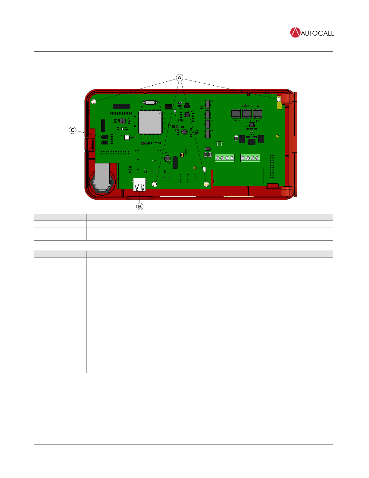
Figure 3: USB location, Annunciator rear view
Callouts Description
A Screw locations
B USB location
C SW9
Table 2: Remote Annunciator main back components
Components Description
USB port (J1) Use for firmware upgrade. To access the USB port, remove the back plate. For more information contact technical
support.
Address switch SW9.1 Use this switch to select the conventional or addressable FACU for the LCD Annunciator.
CAUTION: After the Annunciator is configured successfully, it is not recommended to change the personality of
the Annunciator from addressable to conventional or conventional to addressable as it will not match the config-
uration settings.
1. To select the Addressable LCD Annunciator:
a. For addressable mode, face SW9.1, then change the position of SW9.1 to the right side, horizontally in
the ON state.
b. Press and hold the RESET key on the Annunciator UI.
c. Apply power to the Annunciator.
d. Wait 5 seconds, then release the RESET key or wait until the Annunciator UI displays the first screen.
2. To select the conventional LCD Annunciator:
a. For conventional mode, face SW9.1, then change the position of SW9.1 to the left side, horizontally in
the OFF state.
b. Press and hold the RESET key on the Annunciator UI.
c. Apply power to the Annunciator.
d. Wait 5 seconds then release the RESET key or wait until the Annunciator UI displays the first screen.
page 6 579-1434AC Rev B
Foundation Series A606-9101 LCD Annunciator Installation Guide
3.1 Specifications
• For use indoors in a dry location.
• All connections are power-limited and supervised.
Table 3: Measurements
Height Length Depth
5 3/8 in. 6 7/8 in. 1 3/8 in.
13.65 cm 17.46 cm 3.49 cm
Table 4: Power requirements and environmental limitations
Measurement type Item Range
Voltage 24 VDC power supply Nominal 24 VDC:
Compatibility range, 16 to 30 VDC
When the LCD back-light is off:
Alarm current: 48 mA
Standby current: 40 mA
Current Maximum current
value
When the LCD back-light is on:
Alarm current: 72 mA
Standby current: 65 mA
Operating range 32°F to 120°F (0°C to 49°C)Temperature
Storage range -4°F to 158°F (-20°C to 70°C)
Humidity Relative humidity The equipment operates normally under non-condensing humidity conditions up to 93%
relative humidity at 90°F (32°C).
page 7 579-1434AC Rev B
Foundation Series A606-9101 LCD Annunciator Installation Guide
4 Mounting instructions
To mount the Annunciator, complete the following steps:
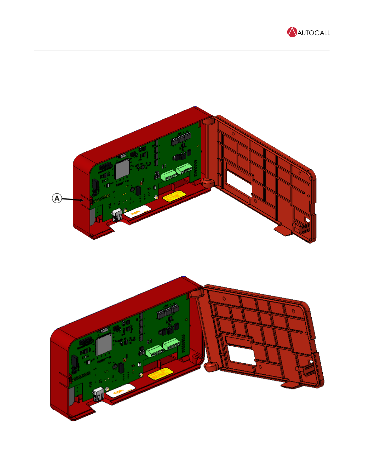
1. Unlock the Annunciator using the B-key provided and press location A to open the backplate as shown in Figure 4.
2. Remove the back plate from housing. To remove the back plate, position the back plate at 90º to the housing as shown in Figure 4 and
then tilt and detach the bottom interface of plate from housing first as shown in Figure 5.
Figure 4: Opening the back plate
See Table in step 3 for callout description.
Figure 5: Detaching the back plate
page 8 579-1434AC Rev B
Foundation Series A606-9101 LCD Annunciator Installation Guide

3. Place the back plate on the mounting surface and mark the location of the four screw holes.
Figure 6: Marking the location of the screw holes
Callouts Description
A Press here
B Back plate
C Screw locations
4. Using the four provided screws, mount the Annunciator back plate on the wall or mounting surface.
5. To attach the back plate to the housing, follow step 2 in reverse, see Figure 7.
Figure 7: Mounting the Annunciator back plate
page 9 579-1434AC Rev B
Foundation Series A606-9101 LCD Annunciator Installation Guide
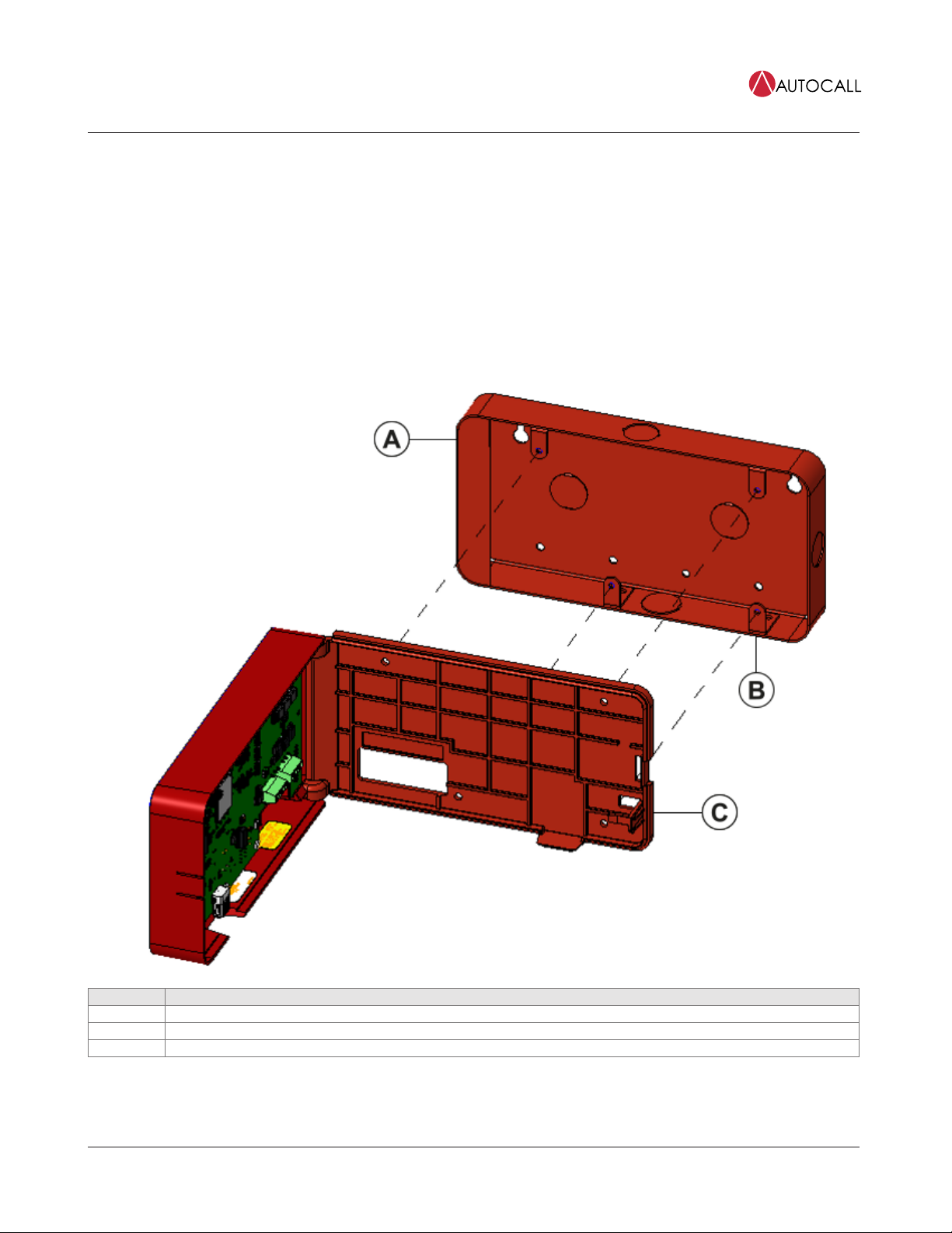
4.1 Mounting the Annunciator using the surface mount box
To mount the Annunciator using the surface mount box, complete the following steps
1. Place the Annunciator on the surface mount box.
2. Carefully align the mounting holes on the Annunciator wall plate with the surface mount box as shown in image
3. Use the four #6-32 screws to mount the wall plate on the surface mount box.
4. UL listed RACO 698 3-1/2D 4 GANG MASONRY BOX must be used for wall mounting application or 2975-9239 for surface mount
applications.
Note:
- Do not over tighten.
- Surface mount box is ordered separately, Ordering ID: 2975-9239.
Figure 8: Mounting the Annunciator using the surface mount box
Callouts Description
A Mounting plate
B Screw locations
C Press to release
page 10 579-1434AC Rev B
Foundation Series A606-9101 LCD Annunciator Installation Guide
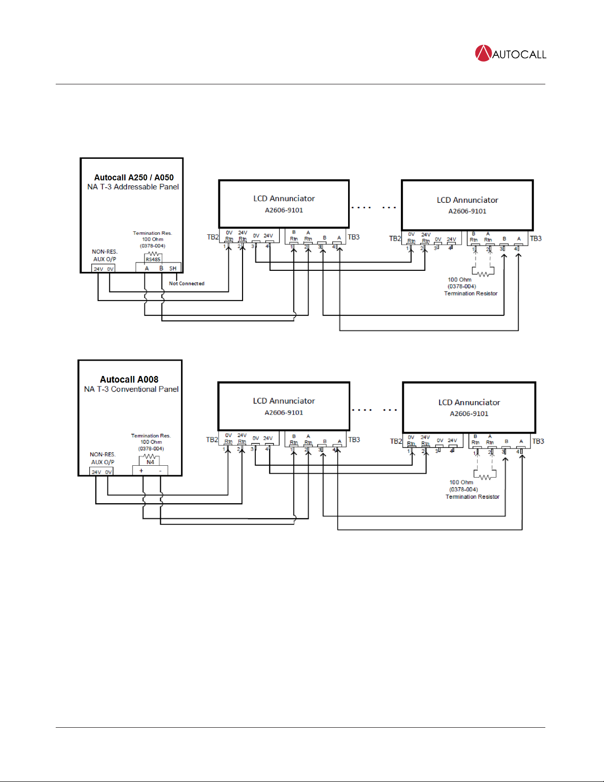
5 Installing the LCD Annunciator
To install the LCD Annunciator with the A008 and A250 FACU, complete the following step:
1. Terminate the annunciators RS485 COMM and power line as shown in Figure 9 and Figure 10 .
Figure 9: Terminating the COMM and power lines with addressable panel
Figure 10: Terminating the COMM and power lines with conventional panel
Note: At the last Annunciator, use a 100 Ohm termination resistor between A Rtn. and B Rtn. of TB3. One termination resistor is
connected to the last Annunciator and the other is at the fire panel terminal block (RS485 / N4 terminal). Termination resistor part
number: 0378-004.
2. A maximum of eight annunciators are supported on A250 and A050 panels.
3. A maximum of four annunciators are supported on a A008 panel.
page 11 579-1434AC Rev B
Foundation Series A606-9101 LCD Annunciator Installation Guide

5.1 Configuring the A008 LCD Annunciator
5.1.1 Powering the Annunciator in conventional mode.
1. Address switch SW9-1 must be in the OFF position. That is, conventional mode.
2. Insert the key into the key switch and rotate it 90 degrees anticlockwise.
3. For the first time that power is applied:
a. Ensure that the communication cable is not connected between the FACU and the Annunciator.
b. Press and hold the RESET key before power is applied.
c. Connect the Annunciator to the power supply or to the panel.
d. After the Annunciator is powered up, wait 5 seconds, then release the RESET key.
e. Wait until Comm Failure message is displayed.
5.1.2 Annunciator configuration menu
CAUTION: To ensure that you do not make any unintended changes, a timeout of 30 seconds is implemented. If you do not press any
key in less than 30 seconds, you are automatically logged out.
1. To enter the configuration menu, press and hold the ENTER key for at least 5 seconds.
2. After the ENTER key is released, the Annunciator displays the configuration menu. Use the Up and Down keys to scroll through
configuration menus. For example the following screen shows the option to set the Annunciator's address.
MENU:
Set Annunc Address
3. The configuration options are:
- Set Annunc Address
- Set Ann. Language
- Software Rev
- Contrast
- Brightness
- Exit
4. After a configuration option is displayed, press and hold the ENTER key for at least 2 seconds. After the ENTER key is released
after at least 2 seconds, actual setting options are displayed.
5. Use the Up and Down keys to set different values. For example, change the address. The address range is 4 to 7.
6. After the chosen value is set, to save the settings, press the ENTER key.
5.1.3 Changing the address of the A008 LCD Annunciator address using the LCD Annunciator
Valid address values are from four to seven. If the Annunciator ID is not set in the Annunciator or there is a communication error between
the FACU and the Annunciator, the Annunciator UI displays error message Comm Failure.
5.1.4 Changing the language of the LCD Annunciator
From the menu, you can select the language to be Spanish, English or Portuguese.
5.1.5 Checking the software version of the LCD Annunciator
The Annunciator displays the software version on the LCD screen. For the software version, no other configuration needs to be done.
5.1.6 Changing the display contrast of the LCD Annunciator
The Annunciator displays the current contrast value on the LCD screen. You can vary the contrast level from 0% to 100% in steps of 10%.
5.1.7 Changing the display brightness of the LCD Annunciator
The Annunciator displays the current brightness value on the LCD screen. You can vary the brightness level from 0% to 100% in steps of
10%
page 12 579-1434AC Rev B
Foundation Series A606-9101 LCD Annunciator Installation Guide

5.2 Configuring A008 FACU for LCD ANN using Panel PC Tool
There is no option to configure the annunciators in the Conventional Panel Programmer (CPP). You can use the personal computer tool to
enable or disable annunciators that are connected to the A008 FACU. To enable or disable annunciators that are connected to the FACU,
complete the following step:
• In the Hardware tab, under the Optional hardware section select the appropriate check box to enable or disable the annunciators
connected to the FACU.
Figure 11: Enabling annunciators using the PC tool
The reference address for the respective annunciators are also visible if the data is read over the CPP UI.
page 13 579-1434AC Rev B
Foundation Series A606-9101 LCD Annunciator Installation Guide

5.3 Configuring A250 and A050 LCD Annunciator using Annunciator UI
5.3.1 Powering the Annunciator in addressable mode
1. Insert the key into the key switch and rotate it 90 degrees anticlockwise.
2. Address switch SW9-1 must be in the ON position. That is, addressable mode.
3. For the first time power is applied to the annunciator:
a. Connect power to the Annunciator.
b. Ensure that the communication cable is not connected between the FACU and the Annunciator.
c. Press and hold the RESET key, then apply power to the Annunciator.
d. After the Annunciator is powered up, wait for 10 seconds, then release the RESET key.
e. Wait until the LCD screen displays serial link is DOWN (wait time is approximately 30 seconds).
Note: Do not press any key until serial link DOWN is displayed.
f. Press and release the ENTER key, the Annunciator prompts to enter an address.
g. Use Up or Down key to change the address. The address varies from one to eight.
h. After address is selected, to save the settings press the ENTER key.
i. Power off the Annunciator.
j. Connect the communication cable between the FACU and the Annunciator.
k. The Annunciator is ready to be enrolled.
5.3.2 Enrolling an Annunciator from a A050 or A250 panel
To enable communication with the panel, enroll the annunciators from a A050 or A250 panel.
1. In the panel, go to Program menu.
2. Press 1-Auto
Enrolling starts and the Annunciators gets enrolled. After the Annunciator is successfully enrolled with the FACU and the panel is fault-free,
the Annunciator's LCD displays information including time and date similar to the following example.
AUTOCALL 2250
SYSTEM NORMAL
10:50:55 20 Apr 2023
5.3.3 Annunciator configuration options
1. Press and hold the ENTER key for at least 5 seconds, then release the ENTER key. The Annunciator displays multiple
configuration options as shown in the following screen.
Annunciator ID lev.1 :MAIN A1
View list AUTOCALL A050-9101
View Log NOT CONFIGURED
> LCD Settings 04:00:58 25 Dec 2019
2. Use the Up and Down keys to select different settings. For example:
- Annunciator ID
- LCD Settings
3. To enter detailed settings for any of these options, press and release the ENTER key.
5.3.4 Address configuration
Use the Up and Down keys to allocate an addresses from one to eight to the Annunciator.
5.3.5 LCD settings
page 14 579-1434AC Rev B
Foundation Series A606-9101 LCD Annunciator Installation Guide

5.3.5.1 LCD backlight
To configure the LCD backlight follow these steps.
1. Use the Up or Down keys to select Set Backlight option from Menu. Press and release the ENTER key to enter the backlight
menu.
2. Use the Up and Down keys to set the required backlight intensity. For each Up or Down key press the LCD backlight intensity
varies and a new set value is saved in the Annunciator's memory.
3. To exit and go back to the previous menu, press and hold the ENTER key for at least 5 seconds.
5.3.5.2 LCD contrast
1. Use the Up and Down keys to select Set Contrast option from Menu. Press the ENTER key to enter the contrast menu.
2. Use the Up and Down keys to set required backlight intensity. For each Up or Down key press the LCD contrast intensity varies
and a new set value is saved in the Annunciator's memory.
3. To exit and go back to the previous menu press and hold the ENTER key for at least 5 seconds.
Note:
• If you press any key the Annunciator LCD backlight turns on for 30 seconds.
• In the case of any event, the LCD's backlight turns on and remains on until the event is handled by the panel. In the case of AC supply
failure, after reporting any event, the backlight turns off after 30 seconds.
• If communication between the FACU and the annunciator is disconnected for more than 60 seconds, the Annunciator displays Serial
Link Down and the Annunciator's buzzer activates. Press the ACK key to silence the buzzer.
page 15 579-1434AC Rev B
Foundation Series A606-9101 LCD Annunciator Installation Guide
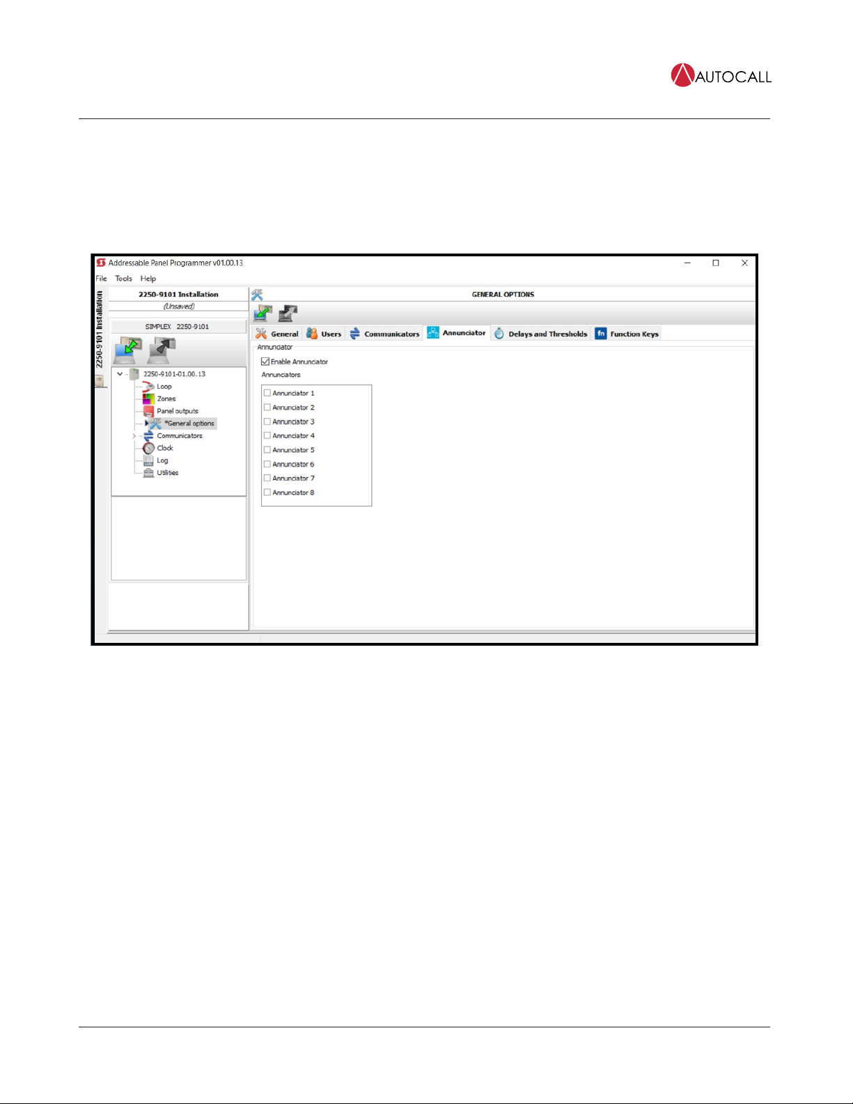
5.4 Configuring A250 and A050 FACUs for LCD Annunciator using PC tool
To configure the A250 FACU using the PC tool, complete the following steps:
1. From the console list, select General Options.
2. From the General Options menu, select the Annunciator tab.
3. To configure the Annunciator select the Enable Annunciator checkbox.
Figure 12: The Enable Annunciator checkbox
You can connect a maximum number of eight annunciators to one FACU.
page 16 579-1434AC Rev B
Foundation Series A606-9101 LCD Annunciator Installation Guide

6 Wiring guidelines
This section contains the wiring guidelines for the LCD Annunciator.
6.1 General wiring guidelines
• All wiring must be copper conductors only.
• Do not use wire lengths in excess of the maximum lengths.
• Underground wiring must be free of water.
• Wires must not be run through elevator shafts.
• You can splice provided you do the following:
- All such connections are soldered with a rosin-core solder, crimped in metal sleeves, or encapsulated with an epoxy resin.
- When solder or crimped metal sleeves are used, the junction is insulated with a high-grade electrical tape as sound as the original
insulating jacket.
- The shield’s continuity is maintained throughout the cable’s length.
• Only system wiring can share the same conduit, see Figure 10 .
6.2 Specific wiring guidelines
• 24 V power wiring must be power limited and communication wiring is supervised and power limited.
• The Remote Annunciator cannot be used with wiring that goes outside the building, above or below ground, unless over voltage
suppression is provided at both ends for both the communication and the power wiring.
Communication and power wiring must meet requirement:
- Model Autocall A2081-9044 overvoltage protectors (200 mA or less).
• For maximum wire lengths with or without circuit protectors, see Table 6.
• If the interconnected control unit is not used to provide operating power to the annunciator, a regulated power-limited, UL-listed 24
VDC power supply for fire protective signaling must be used.
• 14 AWG to 22 AWG twisted pair wiring is required for RS485 communications.
6.3 Wire lengths
• When using multiple annunciators and runs, the total of all runs must not exceed 4000 ft. for bus style wiring.
• For A050 and A250 panels, when using multiple annunciators and runs, the total of all runs must not exceed 2500 ft. for T-Tap style
wiring.
• Four A2081-9044 Over Voltage Protectors is the maximum number that can be on any single communication loop.
6.3.1 Calculation of Annunciator wiring distance
In general, the wire length is limited by resistance but for small AWG wires the capacitive component dominates and becomes the limiting
factor. The resistance for each 1000 ft. wire with respect to its AWG, is shown in the following table:
Table 5: Resistance for each 1000 ft wire with respect to AWG
AWG Resistance (ohm) for each 1000 ft, Rref
22 16.14
20 10.15
18 6.385
16 4.016
14 2.25
The LCD ANN maximum distance supported is 4000 ft. (1200 m) regardless of gauge used. This distance decreases as the connected
Annunciator number increases (increase in worst case current consumption). You can use the following formula to find the maximum
supported distance for the used case:
Maximum wire length = (3V / (Rref x MIC)) x 1000 ft.
Where MIC (Maximum Instantaneous Current) can be found out by:
MIC = (0.075 x Number of annunciators) Amps
For instance, number of Annunciator selected = 6; AWG = 18 AWG
MIC (Maximum Instantaneous Current) = 0.075 x 6 = 0.600 A
Maximum wire length = (3V / (6.385 x 0.600)) x 1000 ft. = 1044 ft.
The following table summarizes maximum distance supported for respective AWG with number of annunciators connected:
page 17 579-1434AC Rev B
Foundation Series A606-9101 LCD Annunciator Installation Guide

Table 6: Maximum distance supported for respective AWG for Annunciator quantity
Maximum
Annunciator QTY
Maximum distance
(ft) w/ 22 AWG
Maximum distance
(ft) w/ 20 AWG
Maximum distance
(ft) w/ 18 AWG
Maximum distance
(ft) w/ 16 AWG
Maximum distance
(ft) w/ 14 AWG
8310 493 783 1244 1980
7354 563 895 1421 2263
6413 657 1044 1658 2640
5496 788 1253 1990 3168
4620 985 1566 2488 3960
3826 1314 2088 3317 4000
21239 1970 3132 4000 4000
12478 3941 4000 4000 4000
Note:
1. A maximum of eight annunciators are supported on A250 and A050 panels.
2. A maximum of four annunciators are supported on A008 panels.
page 18 579-1434AC Rev B
Foundation Series A606-9101 LCD Annunciator Installation Guide
Table of contents
Other Autocall Fire Alarm manuals


Popular Fire Alarm manuals by other brands

Zeta Alarm Systems
Zeta Alarm Systems SIMPLICITY MICRO instruction manual

Secutron
Secutron MRM-800 Series quick start guide

Cooper Notification
Cooper Notification ST-C installation instructions

Tecnoalarm
Tecnoalarm Tecnofire TFA2-596 Installation

Tyco
Tyco F3200 Installation & programming manual

Bosch
Bosch FPC-500 Operation manual


Potter
Potter PAD100-PSSA installation manual

Notifier
Notifier NBG-12S installation manual

Ampac
Ampac XP95 installation guide

GST
GST DC-9102E user guide

Siemens
Siemens Cerberus PRO FS720 Components/Spare parts/Repair parts

Kidde Fire Systems
Kidde Fire Systems PEGAsys Installation, operation and maintenance manual