E2S D1xB2XH1 User manual

_______________________________________________________________________________________________________________________________
European Safety Systems Ltd. Impress House, Mansell Road, London, W3 7QH, UK sales@e-2-s.com Tel: +44 (0)208 743 8880
www.e-2-s.com Fax: +44 (0)208 740 4200
Document No. D191-00-251-IS-SC_Issue_E 27/04/2018 Sheet 1 of 7
Instruction Manual
D1xB2XH1 & D1xB2XH2 Xenon Beacons
For use in hazardous Locations
Marking Information
Unit Type No.: D1xB2XH1
D1xB2XH2
Input Voltage: DC Unit Range : 20-28Vdc
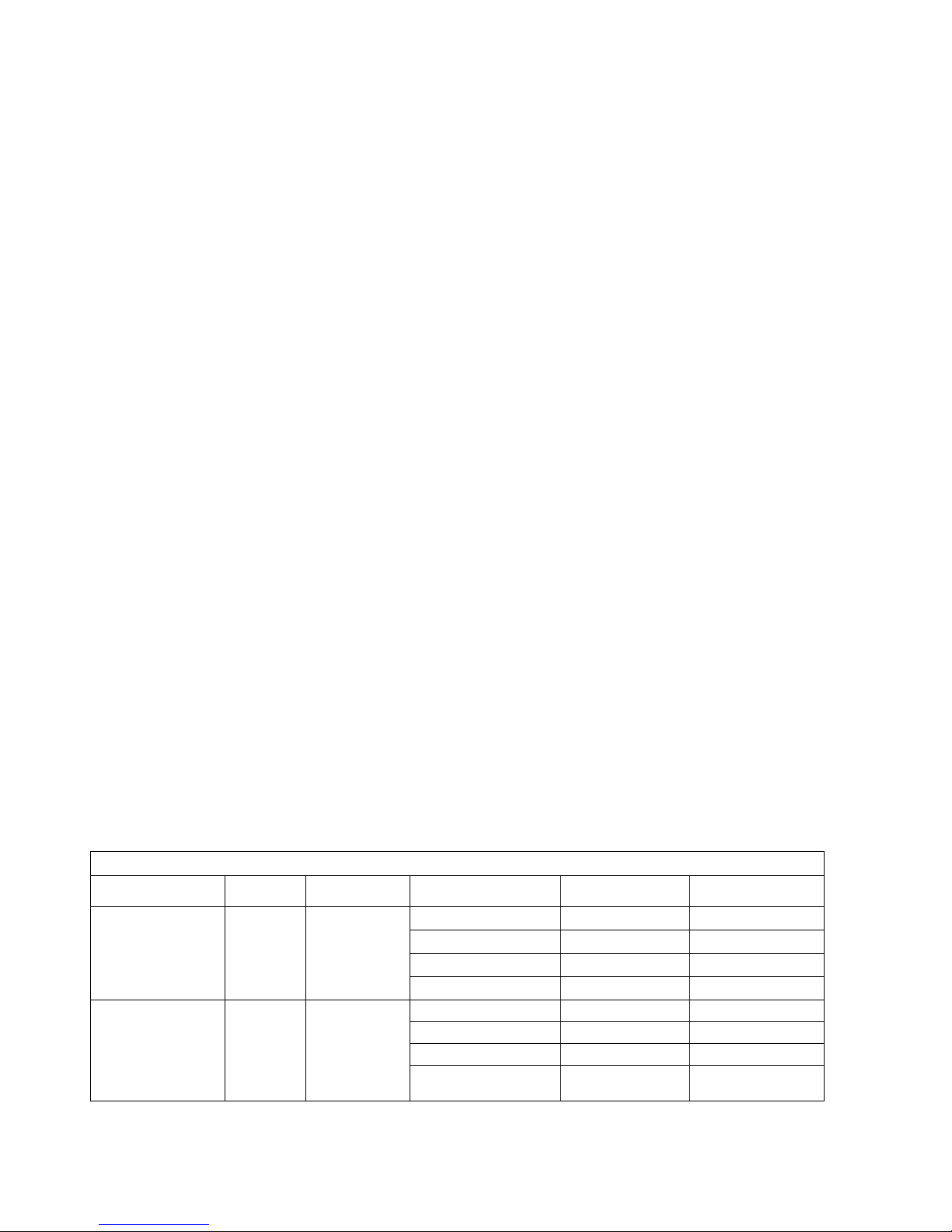
Codes: D1xB2XH1: 10J Xenon Beacon
Class / Division Ratings for US
Class I Div 1 Group ABCD T5 Ta -55°C to +80°C
Class I Div 1 Group ABCD T6 Ta -55°C to +60°C
Class / Division Ratings for Canada
Class I Div 1 Group CD T5 Ta -55°C to +80°C
Class I Div 1 Group CD T6 Ta -55°C to +60°C
Class / Division Ratings for US and Canada
Class II Div 1 Group EFG T4A Ta -55°C to +80°C
Class II Div 1 Group EFG T5 Ta -55°C to +65°C
Class II Div 1 Group EFG T6 Ta -55°C to +50°C
Class III Div 1 Ta -55°C to +80°C
Class / Zone ratings for US
Class I Zone 1 AEx db IIC T5 Ta -55°C to +80°C
Class I Zone 1 AEx db IIC T6 Ta -55°C to +60°C
Zone 21 AEx tb IIIC 107°CTa -55°C to +80°C
Class / Zone ratings for Canada
Ex db IIC T5 Ta -55°C to +80°C
Ex db IIC T6 Ta -55°C to +60°C
Ex tb IIIC 107°C Ta -55°C to +80°C
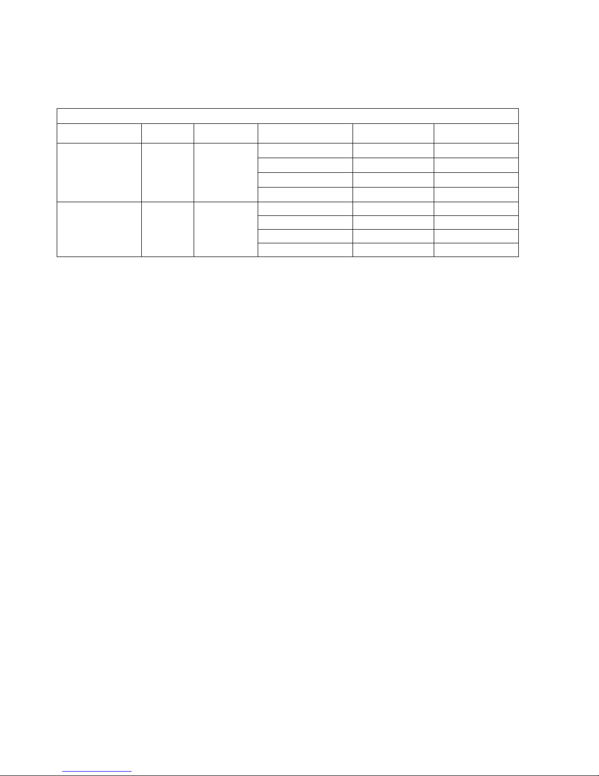
D1xB2XH2: 21J Xenon Beacon
Class / Division Ratings for US
Class I Div 1 Group ABCD T4A Ta -55°C to +80°C
Class I Div 1 Group ABCD T5 Ta -55°C to +55°C
Class I Div 1 Group ABCD T6 Ta -55°C to +40°C
Class / Division Ratings for Canada
Class I Div 1 Group CD T4A Ta -55°C to +80°C
Class I Div 1 Group CD T5 Ta -55°C to +55°C
Class I Div 1 Group CD T6 Ta -55°C to +40°C
Class / Division Ratings for US and Canada
Class II Div 1 Group EFG T4 Ta -55°C to +80°C
Class II Div 1 Group EFG T4A Ta -55°C to +60°C
Class III Div 1 Ta -55°C to +80°C
Class / Zone ratings for US
Class I Zone 1 AEx db IIC T4 Ta -55°C to +80°C
Class I Zone 1 AEx db IIC T5 Ta -55°C to +55°C
Class I Zone 1 AEx db IIC T6 Ta -55°C to +40°C
Zone 21 AEx tb IIIC 131°CTa -55°C to +80°C
Class / Zone ratings for Canada
Ex db IIC T4 Ta -55°C to +80°C
Ex db IIC T5 Ta -55°C to +55°C
Ex db IIC T6 Ta -55°C to +40°C
Ex tb IIIC 131°C Ta -55°C to +80°C
The certification approval has validated continuous use up to 38C ambient and are for transient use up to 80C ambient

_______________________________________________________________________________________________________________________________
European Safety Systems Ltd. Impress House, Mansell Road, London, W3 7QH, UK [email protected]m Tel: +44 (0)208 743 8880
www.e-2-s.com Fax: +44 (0)208 740 4200
Document No. D191-00-251-IS-SC_Issue_E 27/04/2018 Sheet 2 of 7
WARNING:
DO NOT OPEN WHEN AN EXPLOSIVE ATMOSPHERE IS PRESENT
DO NOT OPEN WHEN ENERGISED
POTENTIAL ELECTROSTATIC CHARGING HAZARD - CLEAN ONLY WITH A DAMP CLOTH
HIGH VOLTAGE SHOCK HAZARD. WAIT 5 MINUTES AFTER REMOVING POWER BEFORE OPENING THE
ENCLOSURE
DO NOT PAINT
TO REDUCE THE RISK OF IGNITION OF HAZARDOUS ATMOSPHERES, CONDUIT RUNS MUST HAVE A
SEALING FITTING CONNECTED WITHIN 18 INCHES OF ENCLOSE
TO PREVENT IGNITION OF GROUP A, B, C AND D ATMOSPHERES - SEE
INSTRUCTION FOR CHEMICAL COMPATIBILITY
AVERTISSEMENT:
NE PAS OUVRIR UN PRESENCE D'ATMOSPHERE EXPLOSIVE
NE PAS OUVRIR ENERGIE
DANGER POTENTIEL CHARGE ÉLECTROSTATIQUE - NETTOYER UNIQUEMENT AVEC UN CHIFFON HUMIDE
HAUT TENSION, RISK DE CHOC. ATTENDEZ 5 MINUTES APRES
AVOIR DEBRANCHE L'ALIMENTATION AVANT D'OUVRIR LA BOITIER
NE PAS PEINTURER
POUR RÉDUIRE LE RISQUE D'INFLAMMATION DES ATMOSPHÈRES DANGEREUSES, LES CONDUITES DE
CONDUIT DOIVENT AVOIR UN RACCORD D'ÉTANCHÉITÉ RACCORDÉ À MOINS DE 18 POUCES DE
L'ENFERMEMENT
POUR PRÉVENIR L'INFLAMMATION DES ATMOSPHÈRES DES GROUPES A, B, C ET D-VOIR L'INSTRUCTION
POUR LA COMPATIBILITÉ CHIMIQUE
Type Approval Standards:
UL 1203
CSA C22.2 No. 30-M1986
CSA C22.2 No. 25-1966
UL1638 & UL1971
CAN/ULC S526
Ingress Protection Ratings
The product is rated for ingress protection as follows:
IP rating per EN60529: IP66
Type rating per UL50E / NEMA250: 4 / 4X / 3R / 13
Suitable for exposure to Acetone , Ammonium Hydroxide , Diethyl Ether , Ethyl Acetate , Ethylene Dichloride , Furfural
, n-hexane , Methyl Ethyl Ketone , Methanol , 2-NitroPropane and Toulene.
Electrical Ratings per UL Listing
13.1 Operating current Consumption
Electrical Ratings
Model Nom.
Voltage
Voltage
Range
Flash Rate Setting Nom. operating
current
#
Max. operating
current
##
D1xB2XH1DC024 24Vdc 20-28Vdc
1Hz (60fpm)* 635 mA 765 mA
1.5Hz (90fpm)* 700 mA 765 mA
1.33Hz (80fpm)* 695 mA 765 mA
Double flash
580 mA 765 mA
D1xB2XH2DC024
24Vdc
20-28Vdc
1Hz (60fpm)* 1165 mA 1360 mA
1.5Hz (90fpm)* 1230 mA 1360 mA
1.33Hz (80fpm)* 1215 mA 1360 mA
Double flash 1085 mA 1360 mA

_______________________________________________________________________________________________________________________________
European Safety Systems Ltd. Impress House, Mansell Road, London, W3 7QH, UK [email protected]m Tel: +44 (0)208 743 8880
www.e-2-s.com Fax: +44 (0)208 740 4200
Document No. D191-00-251-IS-SC_Issue_E 27/04/2018 Sheet 3 of 7
* Flash rates Public Mode Fire
# nominal rms current at nominal voltage
## max. rms current at worst-case voltage in voltage range.
Surge Current for Fire Alarm use per UL Listing
Surge Currents
Model Nom.
Vol
tage
Voltage
Range
Flash Rate Setting Init, Peak Surge
Current (A)
Init. RMS Surge
Current (mA)
D1xB2XH1DC024 24Vdc 20-28Vdc
1Hz (60fpm) 1150 mA 697 mA
1.5Hz (90fpm) 1100 mA 742 mA
1.33Hz (80fpm) 1090 mA 680 mA
Double flash
1070 mA 639 mA
D1xB2XH2DC024 24Vdc 20-28Vdc
1Hz (60fpm) 1590 mA 1180 mA
1.5Hz (90fpm) 1590 mA 1120 mA
1.33Hz (80fpm) 1710 mA 1130 mA
Double flash 1650 mA 1200 mA
Surge current given at worst case voltage
Installation
There are no restrictions on unit orientation.
Safe Installation Requirements
To maintain the ingress protection rating and mode of protection, the cable entries must be fitted with suitably rated cable
entry and/or blanking devices during installation. If conduit is used for installation, seal conduit within 18 inches from the
enclosure.
If entries are fitted with adaptors they must be suitably rated for the application. Fitting of blanking elements into adaptors
is not permitted.
Connections are to be made into the terminal blocks using solid or stranded wire, sizes 0.5-2.5mm2 / AWG 20-14. Wire
insulation needs to be stripped 6-7mm. Wires may be fitted securely with crimped ferrules. Terminal screws need to be
tightened down with a tightening torque of 0.4 Nm / 3.5 Lb-in.
Earthing connections should be made to the Internal Earth terminal in the explosionproof chamber or the external earth
stud.
Check that the ‘O’ ring seal is in place before replacing the explosionproof cover.
Selection of Cable, Cable Glands, Blanking Elements & Adapters
When selecting the cable size, consideration must be given to the input current that each unit draws (see Table), the number of
beacons on the line and the length of the cable runs. The cable size selected must have the necessary capacity to provide the input
current to all of the sounders connected to the line.
When selecting the cable size consideration must be given to the voltage drop over the length of the cable run to ensure the min. input
voltage at the point of use (voltage range)
The voltage drop depends on:
- The total current draw if the devices installed on this cable run
- The wire size and total length of the cable run, determining the total resistance of this cable run
- The minimum output voltage supplied by the power supply
The voltage drop and input voltage at the point of use can be calculated.
Total Wire resistance =
Wire resistance / 1000ft x length of cable run x 2

_______________________________________________________________________________________________________________________________
European Safety Systems Ltd. Impress House, Mansell Road, London, W3 7QH, UK [email protected]m Tel: +44 (0)208 743 8880
www.e-2-s.com Fax: +44 (0)208 740 4200
Document No. D191-00-251-IS-SC_Issue_E 27/04/2018 Sheet 4 of 7
(length of cable run needs to be multiplied by two to account for two wires going to and from the unit)
Total current draw =
Current draw per unit x number of units
Voltage Drop = Total current draw x Total wire resistance
Minimum output of power supply =
Min. voltage at point of use + voltage drop
Flash Rate Settings
The D1xB2XH1 & D1xB2XH2 beacons can produce different flash patterns as shown in Table. The flash patterns are selected by
operation of the flash setting DIP switch on the PCBA
(*setting permitted for use as public mode fire alarm device)
Fig. 8 Dip Switch
1=ON; 0=OFF
Example shown: 10 = Flashing 1.5Hz
(Default setting is 00 1Hz)
Line Monitoring
All DC units have a blocking diode fitted in their supply input lines.
An end of line monitoring diode or an end of line monitoring resistor can be connected across the +ve and –ve terminals
in the flameproof chamber.
If an end of line resistor is used it must have the following values:
Minimum resistance 3K3 Ohms Minimum Power 0.5W
Minimum resistance 500 Ohms Minimum Power 2.0W
Switch
Setting S1 Mode
00 1Hz* (60FPM)
01 1.33Hz* (80FPM)
10 1.5Hz* (90FPM)
11 Double Flash

_______________________________________________________________________________________________________________________________
European Safety Systems Ltd. Impress House, Mansell Road, London, W3 7QH, UK [email protected]m Tel: +44 (0)208 743 8880
www.e-2-s.com Fax: +44 (0)208 740 4200
Document No. D191-00-251-IS-SC_Issue_E 27/04/2018 Sheet 5 of 7
Light output for Fire alarm use
In order to meet the requirements for UL 1971 & UL1638
for Public Mode Fire alarm Use when used with 1Hz (60FPM),
1.5Hz (90FPM) & 1.33Hz (80FPM) the installation must be
carried out to the correct NFPA standards and guidelines
or CEC regulations.
Horizontal Light Output Dispersion for
wall mounting – public mode
Horizontal dispersion angles for wall mounting
D1xB2XH1 - Horizontal Light Output Dispersion for Wall Mounting
Viewing Angle % Of Rating
Intensity (cd) at
1Hz flash rate
(60FPM)
Intensity (cd) at
1.5Hz flash rate
(90FPM)
Intensity (cd) at
1.33Hz flash rate
(80FPM)
0
⁰
100
86.37
51.65
58.57
5-25
⁰
90
77.73
46.49
52.71
30-45
⁰
75
64.78
38.74
43.93
50
⁰
55
47.50
28.41
32.21
55
⁰
45
38.87
23.24
26.36
60
⁰
40
34.55
20.66
23.43
65
⁰
35
30.23
18.08
20.50
70
⁰
35
30.23
18.08
20.50
75
⁰
30
25.91
15.50
17.57
80
⁰
30
25.91
15.50
17.57
85
⁰
25
21.59
12.91
14.64
90
⁰
25
21.59
12.91
14.64
Compound 45
⁰
to Right 24
20.73
12.40
14.06
Compound 45
⁰
to Left 24
20.73
12.40
14.06
D1xB2XH2 - Horizontal Light Output Dispersion for Wall Mounting
Viewing Angle % Of Rating
Intensity (cd) at
1Hz flash rate
(60FPM)
Intensity (cd) at
1.5Hz flash rate
(90FPM)
Intensity (cd) at
1.33Hz flash rate
(80FPM)
0
⁰
100
190.60
114.69
128.48
5-25
⁰
90
171.54
103.22
115.63
30-45
⁰
75
142.95
86.02
96.36
50
⁰
55
104.83
63.08
70.66
55
⁰
45
85.77
51.61
57.82
60
⁰
40
76.24
45.88
51.39
65
⁰
35
66.71
40.14
44.97
70
⁰
35
66.71
40.14
44.97
75
⁰
30
57.18
34.41
38.54
80
⁰
30
57.18
34.41
38.54
85
⁰
25
47.65
28.67
32.12
90
⁰
25
47.65
28.67
32.12
Compound 45
⁰
to Right 24
45.74
27.53
30.84
Compound 45
⁰
to Left 24
45.74
27.53
30.84

_______________________________________________________________________________________________________________________________
European Safety Systems Ltd. Impress House, Mansell Road, London, W3 7QH, UK [email protected]m Tel: +44 (0)208 743 8880
www.e-2-s.com Fax: +44 (0)208 740 4200
Document No. D191-00-251-IS-SC_Issue_E 27/04/2018 Sheet 6 of 7
Vertical Light Output Dispersion for
wall mounting – public mode
Vertical dispersion angles for wall mounting
D1xB2XH1 - Vertical Light Output Dispersion for Wall Mounting
Viewing
Angle % Of Rating
Intensity (cd) at
1Hz flash rate
(60FPM)
Intensity (cd) at
1.5Hz flash rate
(90FPM)
Intensity (cd) at
1.33Hz flash rate
(80FPM)
0° 100
86.37
51.65
58.57
5-30° 90
77.73
46.49
52.71
35° 65
56.14
33.57
38.07
40° 46
39.73
23.76
26.94
45° 34
29.37
17.56
19.91
50° 27
23.32
13.95
15.81
55° 22
19.00
11.36
12.89
60° 18
15.55
9.30
10.54
65° 16
13.82
8.26
9.37
70° 15
12.96
7.75
8.79
75° 13
11.23
6.71
7.61
80-90° 12
10.36
6.20
7.03
D1xB2XH2 - Vertical Light Output Dispersion for Wall Mounting
Viewing
Angle % Of Rating
Intensity (cd) at
1Hz flash rate
(60FPM)
Intensity (cd) at
1.5Hz flash rate
(90FPM)
Intensity (cd) at
1.33Hz flash rate
(80FPM)
0° 100
190.60
114.69
128.48
5-30° 90
171.54
103.22
115.63
35° 65
123.89
74.55
83.51
40° 46
87.68
52.76
59.10
45° 34
64.80
38.99
43.68
50° 27
51.46
30.97
34.69
55° 22
41.93
25.23
28.27
60° 18
34.31
20.64
23.13
65° 16
30.50
18.35
20.56
70° 15
28.59
17.20
19.27
75° 13
24.78
14.91
16.70
80-90° 12
22.87
13.76
15.42

_______________________________________________________________________________________________________________________________
European Safety Systems Ltd. Impress House, Mansell Road, London, W3 7QH, UK [email protected]m Tel: +44 (0)208 743 8880
www.e-2-s.com Fax: +44 (0)208 740 4200
Document No. D191-00-251-IS-SC_Issue_E 27/04/2018 Sheet 7 of 7
Vertical Light Output Dispersion
for ceiling mounting – public mode
Vertical dispersion angles for ceiling mounting X and Y planes
All light output ratings min. values as per UL 1971 / UL1638 / CAN/ULC-S526 at worst-case (min.) input voltage.
D1xB2XH1 - Vertical Light Output Dispersion for Ceiling Mounting
Viewing Angle % Of Rating
Intensity (cd) at
1Hz flash rate
(60
FPM)
Intensity (cd) at
1.5Hz flash rate
(90FPM)
Intensity (cd) at
1.33Hz flash rate
(80FPM)
0
⁰
100
86.37
51.65
58.57
5-25
⁰
90
77.73
46.49
52.71
30-45
⁰
75
64.78
38.74
43.93
50
⁰
55
47.50
28.41
32.21
55
⁰
45
38.87
23.24
26.36
60
⁰
40
34.55
20.66
23.43
65
⁰
35
30.23
18.08
20.50
70
⁰
35
30.23
18.08
20.50
75
⁰
30
25.91
15.50
17.57
80
⁰
30
25.91
15.50
17.57
85
⁰
25
21.59
12.91
14.64
90
⁰
25
21.59
12.91
14.64
D1xB2XH2 - Vertical Light Output Dispersion for Ceiling Mounting
Viewing Angle % Of Rating
Intensity (cd) at
1Hz flash rate
(60FPM)
Intensity (cd) at
1.5Hz flash rate
(90
FPM)
Intensity (cd) at
1.33Hz flash rate
(80FPM)
0
⁰
100
190.6
114.69
128.48
5-25
⁰
90
171.54
103.22
115.63
30-45
⁰
75
142.95
86.02
96.36
50
⁰
55
104.83
63.08
70.66
55
⁰
45
85.77
51.61
57.82
60
⁰
40
76.24
45.88
51.39
65
⁰
35
66.71
40.14
44.97
70
⁰
35
66.71
40.14
44.97
75
⁰
30
57.18
34.41
38.54
80
⁰
30
57.18
34.41
38.54
85
⁰
25
47.65
28.67
32.12
90
⁰
25
47.65
28.67
32.12
This manual suits for next models
1
Table of contents
Other E2S Fire Alarm manuals
Popular Fire Alarm manuals by other brands

Panasonic
Panasonic Firetracker FT1020G3 CIE Technical and Programming Manual

Bosch
Bosch B925F installation guide

Ansul
Ansul Checkfire MP-N Installation, Recharge, Inspection and Maintenance Manual

System Sensor
System Sensor ECO1002ABLINK Installation and maintenance instructions

Honeywell
Honeywell Notifier ID60 operating manual

Advanced
Advanced MxPro4 Series Installation Sheet & Quick Reference Guide