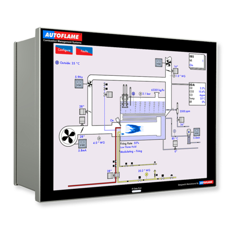
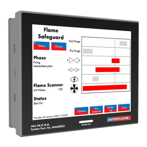
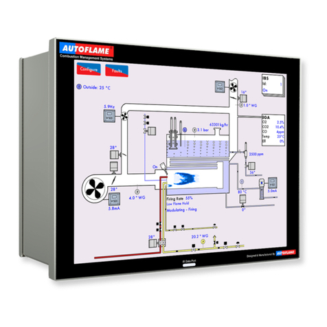
AUTOFLAME Mini Mk8 M.M. User manual

Combustion Management Systems
AUTOFLAME MK8
FLAME SAFEGUARD
CONTROLLER MANUAL
MM80001/FSG
08 FEB 2024

COMBUSTION MANAGEMENT SYSTEMS
Autoflame Engineering Ltd.
Unit 1-2 Concorde Business Centre
Airport Industrial Estate
Wireless Road, Biggin Hill
Kent TN16 3YN
United Kingdom
Tel:
+44 (0)1959 578 820
Email:
technicalsupport@autoflame.com
Web:
www.autoflame.com
AUTOFLAME MK8
FLAME SAFEGUARD
MANUAL
MM80001/FSG
08 FEB 2024
This manual and all the information contained herein is copyright of Autoflame Engineering Ltd. It may not be
copied in the whole or part without the consent of the Managing Director.
Autoflame Engineering Ltd’s policy is one of continuous improvement in both design and manufacture. We
therefore reserve the right to amend specifications and/or data without prior notice. All details contained in this
manual are correct at the time of going to print.

Important Notes
A knowledge of combustion related procedures and commissioning is essential before embarking work on any of
the MM / EGA systems. This is for safety reasons and effective use of the MM / EGA system. Hands on training
is required. For details on schedules and fees relating to group training courses and individual instruction, please
contact the Autoflame Engineering Ltd. offices at the address listed herein.
Short Form - General Terms and Conditions
A full statement of our business terms and conditions are printed on the reverse of all invoices. A copy of these
can be issued upon application, if requested in writing.
The System equipment and control concepts referred to in this Manual MUST be installed, commissioned and
applied by personnel skilled in the various technical disciplines that are inherent to the Autoflame product range,
i.e. combustion, electrical and control.
The sale of Autoflame’s systems and equipment referred to in this Manual assume that the dealer, purchaser and
installer has the necessary skills at his disposal. i.e. A high degree of combustion engineering experience, and a
thorough understanding of the local electrical codes of practice concerning boilers, burners and their ancillary
systems and equipment.
Autoflame’s warranty from point of sale
•Two years on all electronic systems and components.
•One year on all mechanical systems, components and sensors.
The warranty assumes that all equipment supplied will be used for the purpose that it was intended and in strict
compliance with our technical recommendations.
Autoflame’s warranty and guarantee is limited strictly to product build quality, and design. Excluded absolutely
are any claims arising from misapplication, incorrect installation and/or incorrect commissioning.

CONTENTS
1
AUTOFLAME FLAME SAFEGUARD OVERVIEW, SPECIFICATIONS AND WIRING...............................13
1.1 Autoflame Flame Safeguard Overview..................................................................................................13
1.1.1
Autoflame Flame Safeguard Main Features..................................................................................14
1.1.2
Fixing Holes and Dimensions ........................................................................................................15
1.2 Installation..............................................................................................................................................16
1.2.1. Humidity.........................................................................................................................................16
1.2.2. Vibration.........................................................................................................................................16
1.2.3. Weather .........................................................................................................................................16
1.2.4. Environmental Classification..........................................................................................................17
1.3 Wiring.....................................................................................................................................................18
1.3.1
Servo Motor Control Schematic Main Board.................................................................................19
1.3.2
On/Off Burner Control Schematic..................................................................................................20
1.3.3
Expansion Board............................................................................................................................21
1.3.4
Fuse Ratings..................................................................................................................................22
1.4 Electrical Specifications .........................................................................................................................23
1.4.1
Classifications................................................................................................................................23
1.4.2
Inputs and Outputs.........................................................................................................................23
1.4.3
Internal Hardware Status Monitoring.............................................................................................23
1.4.4
Input Checks..................................................................................................................................23
1.4.5
Expansion Board Inputs and Outputs............................................................................................24
1.4.6
Cable Specifications ......................................................................................................................25
1.4.7
Terminals Description....................................................................................................................26
1.4.8
Expansion Board Terminals Description........................................................................................28
1.5 Relay Box...............................................................................................................................................29
1.5.1
Relay Box Terminal Description ....................................................................................................29
1.6 Converting a Flame Safeguard unit to an Autoflame Flame Safeguard................................................31
1.6.1
Converting Honeywell Flame Safeguard Units..............................................................................31
1.6.2
Converting Fireye Flame Safeguard Units ....................................................................................33
1.7 Standards...............................................................................................................................................34
2
OPTIONS AND PARAMETERS....................................................................................................................35
2.1 Options...................................................................................................................................................35
2.2 Parameters ............................................................................................................................................59
2.3 Language...............................................................................................................................................69
2.4 Set Clock................................................................................................................................................70
3
CONFIGURING THE AUTOFLAME FLAME SAFEGUARD UNIT ..............................................................71
3.1 Overview................................................................................................................................................71
3.1.1
Single Servo Burner Set up...........................................................................................................72
3.1.2
On/Off Burner Set up.....................................................................................................................72
3.1.3
Wiring Checks................................................................................................................................72
3.2 Installation Checks.................................................................................................................................73
3.2.1
Configuration Checks ....................................................................................................................73
3.2.2
Operational Checks .......................................................................................................................73
3.2.3
Installation Precautions..................................................................................................................73
3.2.4
Maintenance and Servicing ...........................................................................................................73
4
GENERAL FEATURES.................................................................................................................................74
4.1 No Pre-Purge.........................................................................................................................................74
4.2 Autoflame Flame Safeguard Flame Detection Using Flame Switch......................................................75
4.3 Terminals 80 and 81 Functions .............................................................................................................76

4.3.1
T80 Functions................................................................................................................................76
4.3.2
T81 Functions................................................................................................................................76
4.4 Valve Proving with Autoflame Gas Sensor............................................................................................77
5
EXPANSION FEATURES .............................................................................................................................78
6
DIRECT MODBUS ........................................................................................................................................79
6.1 Overview................................................................................................................................................79
6.2 Direct Modbus Expansion Options ........................................................................................................80
6.3 Setup and Configuration........................................................................................................................81
6.4 Modbus Addresses................................................................................................................................82
6.4.1
Modbus Address for MM Status (30102).......................................................................................91
7
FIRST OUTS..................................................................................................................................................92
7.1 Overview of First Outs...........................................................................................................................92
7.2 First Outs Expansion Options................................................................................................................92
7.3 First Outs Configuration.........................................................................................................................93
7.3.1
Enabling First Outs ........................................................................................................................93
7.3.2
Accessing First Outs......................................................................................................................93
7.3.3
First Out Function ..........................................................................................................................94
7.3.4
Edit First Out Label........................................................................................................................95
7.3.5
First Outs Interlock.........................................................................................................................96
8
OPERATION..................................................................................................................................................98
8.1 Home Screen.........................................................................................................................................98
8.1.1
Flame Safeguard - History.............................................................................................................99
8.1.2
Options.........................................................................................................................................100
8.1.3
Parameters ..................................................................................................................................101
8.1.4
Expansion....................................................................................................................................102
8.1.5
Run Times....................................................................................................................................103
8.1.6
System Log..................................................................................................................................106
8.1.7
First Outs .....................................................................................................................................107
8.1.8
Faults...........................................................................................................................................108
9
BURNER START-UP SEQUENCE.............................................................................................................109
9.1 Recycle................................................................................................................................................110
9.2 Standby................................................................................................................................................111
9.3 Internal Relay Tests.............................................................................................................................112
9.4 CPI Input..............................................................................................................................................113
9.5 Valve Proving.......................................................................................................................................114
9.6 Wait for Air Switch ...............................................................................................................................118
9.7 Purge ...................................................................................................................................................119
9.8 Ignition .................................................................................................................................................122
9.9 Pilot......................................................................................................................................................124
9.10 Proving.................................................................................................................................................127
9.11 Firing....................................................................................................................................................128
9.12 Post Purge...........................................................................................................................................129
10
UNLOCKING THE AUTOFLAME FLAME SAFEGUARD UNIT TO A MK8 MM.......................................130
10.1 Fully Unlocking the Autoflame Flame Safeguard Controller................................................................130
11
ERRORS AND LOCKOUTS .......................................................................................................................133
11.1 Errors...................................................................................................................................................133
11.2 Lockouts...............................................................................................................................................137
11.3 Alarms and Warnings...........................................................................................................................142
11.4 Settings Conflicts.................................................................................................................................150

1
Autoflame Flame Safeguard Overview, Specifications and Wiring
Flame Safeguard (MM80001/FSG) Manual
Page | 12
VERY IMPORTANT SAFETY NOTES
Please fully read and understand the following notes before commencing with any
work related to the Mk8 MM Flame Safeguard Controller. Failing to do so can
result in serious injury or even death, and can cause serious equipment and
substantial property damage.
Any person working on a boiler must be adequately trained and have a
thorough understanding and appreciation of the boiler plant.
It is the responsibility of the technician working on the plant to ensure that the system
operation meets all local codes and regulations.
Options, Parameters and Expansion Options must only be changed by an Autoflame-trained
and certified technician who has thorough understanding of the Autoflame combustion
control systems and boiler/combustion control in general. Any person changing these
settings without undergoing the necessary training and gaining an understanding of the
boiler plant may place themselves and others in a potentially dangerous situation or cause
permanent equipment damage.
Modification to the Autoflame system settings should only ever be carried out by qualified
combustion engineers. Changes to the Autoflame control system setuphas the potential
to make the controller operate in an unstable and potentially unsafe manner.
Commissioning or burner start-up must only be carried out by a an Autoflame- trained and
certified technician.
The commissioning procedure as described must be strictly adhered to. Anybody
commissioning an Autoflame system must be trained in operating combustion equipment
safely.
Autoflame products must only be installed, set up, commissioned and adjusted by an
Autoflame certified technician.
The fundamental idea of the system is to set a fuel valve position and then set a
corresponding air damper position. Care must be taken when adjusting the fuel and air
positions so as not to create any unstable or hazardous combustion conditions, e.g. moving
the fuel valve to the open position without increasing the air damper position. Improper use
may result in property damage, serious physical injury or death.
Electrical connections are live, make sure to fully and safely isolate the mains power before
carrying out any work related to the wiring connections, failure to do so may result in
serious physical injury or death.
If you are unclear about anything related to the Autoflame system, please contact
Autoflame for technical advice.

1
Autoflame Flame Safeguard Overview, Specifications and Wiring
Flame Safeguard (MM80001/FSG) Manual
Page | 13
1
AUTOFLAME FLAME SAFEGUARD OVERVIEW, SPECIFICATIONS AND
WIRING
1.1 Autoflame Flame Safeguard Overview
The Autoflame Flame Safeguard unit or MM80001/FSG is a version of the Micro-Modulating system that provides
an easily programmable and flexible means of providing the flame safeguard aspects of controlling a
boiler/burner.
This control module encompasses all the functions required for reliable flame safeguard management. Built into
this system is a fully automated flame safeguard, valve proving system and a 12.1” multi-touch screen interface.
MODBUS (MK8006) connectivity & First Outs (MK8007) requires unlock codes to use these features.
With the Mk8 MM, it is possible to control all boiler processes from a single 12.1” multi-touch screen interface
without any added module.
This system monitors the flame safeguard, as it checks on the flame of the burner from the use of a UV, Flame
Switch, or IR Scanner.
Additional expansion features include:
•Direct Modbus connectivity
•First out annunciation

1
Autoflame Flame Safeguard Overview, Specifications and Wiring
Flame Safeguard (MM80001/FSG) Manual
Page | 14
1.1.1
Autoflame Flame Safeguard Main Features
•12.1” Full colour touch screen
•120V or 230V standard operation 50/60Hz
•4 independent fuel programmes
•Internal flame safeguard –full flame supervision with self-check UV, IR & Flame switch.
•Dual flame scanner operation (IR and UV scanners)
•Gas valve train leak supervision via Autoflame gas pressure sensor as a low gas pressure limit
•Air pressure proving and monitoring via Air switch
•128 lockouts, errors, alarms and warnings stored with date, time, phase and reset
•1000 entry system log stored with date, time and status
•Burner control safety times user selectable
•Password protection of all safety related functions
•Infra-red port for upload/download of commission data
•First out annunciation inputs
•Download / upload all commissioning data and controller settings from MM module to a PC via
Bluetooth or IR
•Direct Modbus communications to BMS or remote monitoring and control
•Flame Safeguard mode, which allows the MM to operate as a standard Flame Safeguard.

1
Autoflame Flame Safeguard Overview, Specifications and Wiring
Flame Safeguard (MM80001/FSG) Manual
Page | 15
1.1.2
Fixing Holes and Dimensions

1
Autoflame Flame Safeguard Overview, Specifications and Wiring
Flame Safeguard (MM80001/FSG) Manual
Page | 16
1.2 Installation
When Installing this Flame Safeguard Controller
Read these instructions carefully. Failure to follow them could damage the product or cause a hazardous
condition.
Check the ratings given in the instructions and marked on the product to ensure the product is suitable for
your application.
The installer must be an Autoflame trained, experienced, flame safeguard service technician.
After installation is complete, check out the product operation as detailed in these instructions.
Never update the software on the Flame Safeguard Controller without consulting Autoflame first. Using
wrong software can damage equipment.
Warning
Fire or Explosion Hazard. Can cause severe injury, death or property damage.
To prevent possible hazardous burner operation, perform verification of safety requirements
each time a Flame Safeguard controller is installed on a burner.
IMPORTANT
For on-off gas-fired systems, some authorities, who have jurisdiction, prohibit the wiring of any limit or
operating contacts in series between the flame safeguard control and the main fuel valve(s).
Two flame detectors can be connected if necessary (see the latest Autoflame Flame Scanners Guide)
This equipment generates, uses and can radiate radio frequency energy, and if not installed and used in
accordance with the instructions, may cause interference to radio communications. It has been tested and
found to comply with the limits for a Class B computing device of part 15 of FCC rules, which are designed
to provide reasonable protection against such interference when operated in a commercial environment.
Operation of this equipment in a residential area may cause interference, in which case the users, at their
own expense, may be required to take whatever measures are required to correct this interference.
This digital apparatus does not exceed the Class B limits for radio noise of digital apparatus set out in the
Radio Interference Regulations of the Canadian Department of Communications.
1.2.1. Humidity
The Autoflame Flame Safeguard controller is designed to operate in a maximum 90 percent relative humidity,
continuous, noncondensing moisture environment.
Condensing moisture can cause a shutdown.
1.2.2. Vibration
Do not install the Flame Safeguard controller where it could be subjected to vibration in excess of 0.5G continuous
maximum vibration.
1.2.3. Weather
The Flame Safeguard controller is not designed to be watertight. If installed outdoors it must be protected by an
approved watertight enclosure. See protection rating in section 1.2.4.

1
Autoflame Flame Safeguard Overview, Specifications and Wiring
Flame Safeguard (MM80001/FSG) Manual
Page | 17
1.2.4. Environmental Classification
The Flame Safeguard Controller meets the following climate specification:
Climate:
Min. Temperature
0°C (32°F)
Recommended Temperature
Less than 40°C (104°F)
Max. Temperature
60°C (140°F)
Humidity
0 to 90% non-condensing
Storage:
Temperature
-20 to 85°C (-4 to 185°F)
Protection
Rating:
The unit is designed to be panel mounted in any orientation and the front
facia is IP65, NEMA4. The back of the unit is IP20, NEMA1.

1
Autoflame Flame Safeguard Overview, Specifications and Wiring
Flame Safeguard (MM80001/FSG) Manual
Page | 18
1.3 Wiring
1. For the internal block diagram of the Autoflame Flame Safeguard controller, see section 1.3.1, 1.3.2
& 1.3.3.
2. Disconnect the power supply before beginning installation to prevent electrical shock and
equipment damage. More than one power disconnect may be involved.
3. All wiring must comply with all applicable electrical codes, ordinances and regulations. Wiring,
where required, must comply with NEC Class 1 wiring.
4. Recommended wire size and type is defined in section 1.4.6 Cable Specifications. For high
temperature installations, use wire selected for a temperature rating above the maximum operating
temperature. All wiring must be moisture resistant.
5. Do not connect more than two wires per terminal. If more than two wires need to be connected to a
terminal, wire into a suitable terminal block in the panel first and from there to the unit terminal with
a single wire.
6. Recommended wire routing for Autoflame Flame Scanners:
a. Do not run high voltage ignition transformer wires in the same conduit with the flame scanner
wiring.
b. Do not route flame scanner wires in a conduit with line voltage circuits.
c. Enclose flame scanner wires in metal conduit.
d. Follow directions given in the Autoflame Flame Scanners Guide.
7. Do not exceed the terminal ratings. Refer to the wiring diagram in section 1.3.1, 1.3.2 & 1.3.3 or to
the ratings in the section 1.4 Electrical Specifications.
8. The voltage tolerance of the power supply must match those of the Flame Safeguard controller. A
separate power supply circuit may be required for the Flame Safeguard controller with the required
disconnect and overload protection added.
9. Check all wiring circuits and complete all the checks before installing the plug-in connectors to the
flame safeguard controller; see section 1.3.1, 1.3.2 & 1.3.3.
10. Install all electrical connectors.
11. Restore power to the panel.
Electrical Shock Hazard
Can cause severe injury, death or property damage.
1. To prevent electrical shock and equipment damage, disconnect the power supply before beginning
installation. More than one power supply disconnect may be involved.
2. Wiring connections for the Autoflame Flame Safeguard controller are unique; therefore, refer to
sections 1.3 and 1.4 for the correct specifications and connections.
3. Wiring must comply with all applicable codes, ordinances and regulations.
4. Wiring, where required, must comply with NEC Class 1 wiring.
5. Loads connected to the Flame Safeguard controller must not exceed those listed on the wiring label
or the specifications (see section 1.4.2 & 1.4.5 of this manual).
6. Limits and interlocks must be rated to carry and break current simultaneously to the ignition
transformer, pilot valve, and main fuel valve(s).
7. All external timers must be listed or component recognized by authorities who have jurisdiction for
the specific purpose for which they are used.

1
Autoflame Flame Safeguard Overview, Specifications and Wiring
Flame Safeguard (MM80001/FSG) Manual
Page | 19
1.3.1
Servo Motor Control Schematic Main Board
72
CALL FOR HEAT
BURNER ON/OFF
AIR PROVING SWITCH
GAS VALVES C.P.I./POC
LOCKOUT RESET
PILOT VALVE
MAIN FUEL VALVE 1
MAIN FUEL VALVE 2
IGNITION TRANSFORMER
GREEN
YELLOW
22
21
N
LIVE/HOT
NEUTRAL
EARTH
BURNER MOTOR 58
BLUE
51
50
51
50
RED
* LIMIT STAT
51
50
S
55
53
52
54
56
57
VENT VALVE
60
59
61
63
62
64
67
66
68
70
69
71
FLAME SWITCH
AT NO FLAME STATE.
78
75
73
74
76
77
80
79
81
83
82
84
FUEL 2
FUEL 1
LINE V
0 V
FUEL 4
FUEL 3
90
87
85
86
88
89
92
91
93
95
94
11
4
2
1
S
3
6
5
7
S
9
8
10
14
S
12
13
S
15
17
16
20
S
18
19
22
21
S
29
26
24
23
25
S
28
27
S
35
30
34
31
49
48
41
38
S
37
S
S
39
40
43
42
45
44
47
46
S
PRE-IGNITION
SAFETY INTERLOCK CIRCUIT
RUNNING INTERLOCK
NON-RECYCLING INTERLOCK
GREEN
YELLOW
BLACK
RED
YELLOW
GREEN
LINE VOLTAGE
LOW VOLTAGE
I.R. SCANNER
MODBUS
27
28
6A FUSED SUPPLY
*NOTE:
HIGH LIMIT STAT
MUST BE
MANUAL RESET
TYPE
U.V. DETECTOR
SELF CHECK
U.V. DETECTOR
EXTERNAL AUXILIARY
DELAY TO PURGE
OUTLET
PRESS.
(OPTIONAL)
GAS
BOOSTER
INLET
PRESS.
6.3A T
T50 TO T64
ALL LOW VOLTAGE WIRING TO THE CONTROL IS TO BE WIRED AS PART OF A CLASS 1 CIRCUIT
BLUE
RED
S
32
33
F4
500mA
F3
500mA
FUSE 1
2A T
SERVO SHORT
CIRCUIT
FUSE 2
LF/20.06.23/MK8 MM FLAME SAFEGUARD ISS3
IF IN DOUBT ASK AUTOFLAME TECHNICAL DEPARTMENT
80
81
HIGH FIRE / PURGE SWITCH
RELAY BOX
HIGH/LOW INITIATE
RELEASE TO MODULATE
B
R
W
69
R1
W1
B1
B
R
W
R
W
B
PRESSURE
CONTROLLER
MOTOR
HF
LF
LOW FIRE / START SWITCH
R1
R2
POWER
COMMON ALARM RELAY 79
BROWN
PURPLE
BLUE
RED
GAS PRESSURE
SENSOR

1
Autoflame Flame Safeguard Overview, Specifications and Wiring
Flame Safeguard (MM80001/FSG) Manual
Page | 20
1.3.2
On/Off Burner Control Schematic
72
CALL FOR HEAT
BURNER ON/OFF
AIR PROVING SWITCH
GAS VALVES C.P.I./POC
LOCKOUT RESET
PILOT VALVE
MAIN FUEL VALVE 1
MAIN FUEL VALVE 2
IGNITION TRANSFORMER
GREEN
YELLOW
22
21
N
LIVE/HOT
NEUTRAL
EARTH
BURNER MOTOR 58
BLUE
51
50
51
50
RED
* LIMIT STAT
51
50
S
55
53
52
54
56
57
VENT VALVE
60
59
61
63
62
64
67
66
68
70
69
71
FLAME SWITCH
AT NO FLAME STATE.
78
75
73
74
76
77
80
79
81
83
82
84
FUEL 2
FUEL 1
LINE V
0 V
FUEL 4
FUEL 3
90
87
85
86
88
89
92
91
93
95
94
11
4
2
1
S
3
6
5
7
S
9
8
10
14
S
12
13
S
15
17
16
20
S
18
19
22
21
S
29
26
24
23
25
S
28
27
S
35
30
34
31
49
48
41
38
S
37
S
S
39
40
43
42
45
44
47
46
S
PRE-IGNITION
SAFETY INTERLOCK CIRCUIT
RUNNING INTERLOCK
NON-RECYCLING INTERLOCK
GREEN
YELLOW
BLACK
RED
YELLOW
GREEN
LINE VOLTAGE
LOW VOLTAGE
I.R. SCANNER
MODBUS
27
28
6A FUSED SUPPLY
*NOTE:
HIGH LIMIT STAT
MUST BE
MANUAL RESET
TYPE
U.V. DETECTOR
SELF CHECK
U.V. DETECTOR
EXTERNAL AUXILIARY
DELAY TO PURGE
OUTLET
PRESS.
(OPTIONAL)
GAS
BOOSTER
INLET
PRESS.
6.3A T
T50 TO T64
ALL LOW VOLTAGE WIRING TO THE CONTROL IS TO BE WIRED AS PART OF A CLASS 1 CIRCUIT
BLUE
RED
S
32
33
F4
500mA
F3
500mA
FUSE 1
2A T
SERVO SHORT
CIRCUIT
FUSE 2
LF/14.07.23/MK8 MM FLAME SAFEGUARD
(ON/OFF BURNER) ISS1
IF IN DOUBT ASK AUTOFLAME TECHNICAL DEPARTMENT
80
81
HIGH FIRE / PURGE SWITCH
LOW FIRE / START SWITCH
COMMON ALARM RELAY 79
BROWN
PURPLE
BLUE
RED
GAS PRESSURE
SENSOR
TR1
70
69
ON DELAY TIMER RELAY
SET DELAY TO 5 SEC.

1
Autoflame Flame Safeguard Overview, Specifications and Wiring
Flame Safeguard (MM80001/FSG) Manual
Page | 21
1.3.3
Expansion Board
LF/20.06.23/MK8 MM FLAME SAFEGUARD ISS3
IF IN DOUBT ASK AUTOFLAME TECHNICAL DEPARTMENT
1-12 FIRST OUT ANNUNCIATION
LINE VOLTAGE INPUTS.
LABELS AND OPERATION, SETUP ON MM
POWER FEED OUTPUT (230/110V) 2 Amp
13-15 FIRST OUT ANNUNCIATION
LINE VOLTAGE INPUTS.
(USER ASSIGNABLE LABELS
SAME AS FIRST OUTS 1-12)
FO1
LINE VOLTAGE
LOW VOLTAGE
ALL LOW VOLTAGE WIRING TO THE CONTROL IS TO BE WIRED AS PART OF A CLASS 1 CIRCUIT
S
P-
FW
P+
S
-
T1
T2
S
-
T3
TW
S
F-
MF
CF
S
I+
V+
IV-
EX+
S
EX-
DT+
DT-
S
DP-
DP+
DPW
S
5T+
5T-
4P-
4P+
6T+
6T-
S
S
3P+
3P-
3T+
3T-
S
1P+
1P-
1T+
1T-
S
2P+
2P-
2T+
2T-
FO2
FO3
FO4
FO5
FO6
FO7
FO8
FO9
FO10
FO11
FO12
PF
FO13
FO14
FO15
HAI
1AI
2AI
M/R
TST
NC
TB
TBI
1LV
H1A
2LV
2LA
HWV
BB
BFW
MVI
MVD
TBD
DCI
DCD
2.5A
F8
FUSE 5
2A
PF OUTPUT
4A
F7
2A
F6

1
Autoflame Flame Safeguard Overview, Specifications and Wiring
Flame Safeguard (MM80001/FSG) Manual
Page | 22
1.3.4
Fuse Ratings
Fu s e
Rating
Sp are P a rt Nu m be r
1
6.3A (T)
FU10026
Fuse 1 protects the mains input to the MM, including the mains output terminals 50 –64.
2
2A (T)
FU10034
Fuse 2 protects the power supply (terminal 69) for the servomotors, alarm and 2 port valve. If this fuse blows,
error ‘Triac Power Supply Error (Check F2)’ will occur.
3
500mA
FU10040
Fuse 3 protects the 13.5V power supply to the oil pressure sensor and IR scanner on terminal 49. If this fuse
blows, error ‘Fused 13.5V Supply Error (Check F3)’ will occur.
4
500mA
FU10040
Fuse 4 protects the 12V power supply to the gas/air pressure sensor and steam pressure detector on
terminals 34 and 39. If this fuse blows, error ‘Fused 12V Supply Error (Check F4)’ will occur.
5
2A (T)
FU10034
Fuse 5 protects the power supply (terminal PF) for the expansion servos and alarm outputs. If fuse 5 blows,
error ‘Expansion PF Output (Check F5)’ will occur.
6
2A
FU10027
Fuse 6 protects the DC circuits. If this fuse blows, the display will be off and both LEDs adjacent to fuse 7
and 8 will be off.
7
4A
FU10050
Fuse 7 protects the internal 5V supply. If this fuse blows the display will be off and the LED adjacent to the
fuse will be off.
8
2.5A
FU10042
Fuse 8 protects the internal 12V supply. If this fuse blows the display will be off and the LED adjacent to the
fuse will be off.

1
Autoflame Flame Safeguard Overview, Specifications and Wiring
Flame Safeguard (MM80001/FSG) Manual
Page | 23
1.4 Electrical Specifications
1.4.1
Classifications
Classification according to BS EN298:2012
Mains Supply:
Single phase 230V, +10%/-15%}
47-63 Hz, unit max. consumption 140W
Single phase 120V, +10%/-15%}
1.4.2
Inputs and Outputs
Output Terminal
Rating (230V)
Rating (120V)
Notes
57
250mA
250mA
Must be connected through contactor
58
250mA
250mA
Must be connected through contactor
59
1A
2A
0.6 power factor
60
1A
2A
0.6 power factor
61
1A
2A
0.6 power factor
62
1A
2A
0.6 power factor
63
1A
2A
0.6 power factor
79
100mA
100mA
To drive relay/lamp only –switched neutral
Max. Load
6A
6A
Electrical Shock Hazard
Can cause severe injury, death or property damage.
•
The high and low voltage connections are not safe to touch. Protection against electric shock is provided by
correct installation.
•
Control voltage cabling should be maximum 10m, screened (if not screened then less than 1m, however
servomotors can be unscreened up to 10m)
•
Any cabling over 10m must have additional surge protection.
•
Low voltage cables should be screened (shielded) cable as specified in section 1.4.6.
•
The burner ‘High Limit Stat’ must be a manual reset type.
•
All external safety devices that require manual reset must be reset external to the Autoflame system and prior
to completing the recycling interlock.
The cover (back plate) of the Flame Safeguard controller must always be re-fitted after the wiring is completed to
prevent access to the electric shock hazard areas, unauthorised wiring modifications or fuse replacement.
1.4.3
Internal Hardware Status Monitoring
The Flame Safeguard controller analyses the integrity of the internal hardware and diagnostics values for key
parameters are available.
The relay safety checks are carried out during every startup sequence and their progress will be displayed on the
screen.
1.4.4
Input Checks
All system input circuits are examined to assure that the Flame Safeguard controller is capable of recognising the
true status of external controls, limits and interlocks. If any input fails this test, a safety shutdown occurs and the fault
will be logged.

1
Autoflame Flame Safeguard Overview, Specifications and Wiring
Flame Safeguard (MM80001/FSG) Manual
Page | 24
1.4.5
Expansion Board Inputs and Outputs
Outputs:
120/230 V
All outputs with the exception of PF are switched neutrals
79
100mA
(alarm indicator on MM board)
PF
Maximum 2A
(load currents for above terminal)
Main Voltage Signal Inputs:
At 120V current loading is approximately maximum 0.7mA per input.At
230V current loading is approximately maximum 1.5mA per input.

1
Autoflame Flame Safeguard Overview, Specifications and Wiring
Flame Safeguard (MM80001/FSG) Manual
Page | 25
1.4.6
Cable Specifications
Low Voltage
The screened cable used for low voltage wiring from the Flame Safeguard unit to the detectors, must conform to
the following specification:
UV scanner cable length should not exceed 25m, all other screened cables should not exceed 50m.
•16/0.2mm PVC insulated overall braid, screened, PVC sheathed.
•Sixteen wires per core
•Diameter of wires in each core 0.2mm
•Rated at 440V AC rms at 1600Hz
•DEF 61-12 current rating per core 2.5A
•Maximum operating temperature 70oC (158oF)
•Nominal conductor area 0.5sq mm per core
•Nominal insulation radial thickness on core 0.45mm
•Nominal conductor diameter per core 0.93mm
•Nominal core resistance at 20oC. 40.1Ω/1000m
•Nominal overall diameter per core 1.83mm
•Fill factor of braid screen 0.7
•Equivalent imperial conductor sizes 14/0.0076
Use the number of cores suitable for the application. A universal part numbering system appears to havebeen
adopted for this type of cable as follows:
•16-2-2C 2 Core
•16-2-3C 3 Core
•16-2-4C 4 Core
•16-2-6C 6 Core
•16-2-8C 8 Core
(5 Core not readily available)
Note: If using 4 Core cable and interference is detected, use 2 sets of 2 Core.
Data Cable
Data cable must be used for communication connections between MM to BMS systems of Modbus RS485.
Communication cable should not exceed 1km.
Types of data cable that can be used:
•
Belden 9501 for 2-core shielded cable (1 twisted pair)
•
Belden 9502 for 4-core shielded cable (2 twisted pairs)
•
STC OS1P24
Samples are available upon request. Low voltage and data cable can be ordered directly from Autoflame
Engineering, please contact Autoflame Sales.

1
Autoflame Flame Safeguard Overview, Specifications and Wiring
Flame Safeguard (MM80001/FSG) Manual
Page | 26
1.4.7
Terminals Description
S
All terminals marked S are internally connected. They are provided for connections to the various
screened cables
21, 22
Connections to an Autoflame self-check UV sensor
27, 28
Communications port connections for Modbus
29, 30
Digital communications connections to an Autoflame IR scanner
31, 32
Digital communications connections to an Autoflame gas pressure sensor
33
0V supply to an Autoflame gas pressure sensor
34
+12V supply to an Autoflame gas pressure sensor
48
0V supply to an Autoflame IR scanner
49
+15V supply to an Autoflame IR scanner
50, 51
Connections to an Autoflame UV scanner
52
Mains voltage input –external auxiliary delay to purge/ secondary proving set in option/parameter
157
53
Mains voltage input –burner on/off signal, running interlock circuit
54
Mains voltage input –air proving switch
55
Mains voltage input - proving circuits, e.g. gas valve proof of closure
56
Mains voltage input - lockout reset
57
Mains voltage output –call for heat
58
Mains voltage output –burner motor
59
Mains voltage output –start/pilot valve
60
Mains voltage output –main fuel valve 1
61
Mains voltage output –main fuel valve 2
62
Mains voltage output –vent valve
63
Mains voltage output –ignition transformer
66
Mains supply –earth
67
Main supply –neutral
68
Mains supply –live/hot
69
Mains voltage output, power to Relay Box (SP80070, SP80070/110)
70
Switched neutral –High/Low Initiate output.
71
Switched neutral –Release to Modulate output.
79
Switched neutral –alarm output for MM lockout/MM error.
80
Low Fire / Start position interlock.
81
High Fire / Purge position interlock.
Other manuals for Mini Mk8 M.M.
2
Table of contents
Other AUTOFLAME Controllers manuals
Popular Controllers manuals by other brands
Kencove
Kencove AG M4 operating instructions
ABB
ABB Totalflow mflo Series Startup guide
Becker
Becker CentralControl CC51 Commissioning instructions
ITT
ITT Conoflow GB50 Series Instruction and maintenance manual
Rosenberg
Rosenberg H42 Series operation instruction
Controlli
Controlli MVH56EA quick start guide
