AUTOFLAME Mk8 MM User manual

Mk8 MM
End User Guide

Mk8 MM
End User Guide
Issued by:
AUTOFLAME ENGINEERING LTD
Unit 1-2, Concorde Business Centre
Airport Industrial Estate, Wireless Road
Biggin Hill, Kent TN16 3YN
Tel: +44 (0)845 872 2000
Fax: +44 (0)845 872 2010
Email: [email protected]
Website: http://www.autoflame.com/
Registered Holder:
Company:
Department:
This manual and all the information contained herein is copyright of
Autoflame Engineering Ltd. It may not be copied in the whole or part without
the consent of the Managing Director.
Autoflame Engineering Ltd’s policy is one of continuous improvement in both
design and manufacture. We therefore reserve the right to amend
specifications and/or data without prior notice. All details contained in this
manual are correct at the time of going to print.

Important Notes
A knowledge of combustion related procedures and commissioning is essential before
embarking work on any of the M.M./E.G.A. systems. This is for safety reasons and
effective use of the M.M./ E.G.A. system. Hands on training is required. For details on
schedules and fees relating to group training courses and individual instruction, please
contact the Autoflame Engineering Ltd. offices at the address listed on the front.
Short Form - General Terms and Conditions
A full statement of our business terms and conditions are printed on the reverse of all
invoices. A copy of these can be issued upon application, if requested in writing.
The System equipment and control concepts referred to in this Manual MUST be installed,
commissioned and applied by personnel skilled in the various technical disciplines that
are inherent to the Autoflame product range, i.e. combustion, electrical and control.
The sale of Autoflame’s systems and equipment referred to in this Manual assume that
the dealer, purchaser and installer has the necessary skills at his disposal. i.e. A high
degree of combustion engineering experience, and a thorough understanding of the
local electrical codes of practice concerning boilers, burners and their ancillary systems
and equipment.
Autoflame’s warranty from point of sale is two years on all electronic systems and
components.
One year on all mechanical systems, components and sensors.
The warranty assumes that all equipment supplied will be used for the purpose that
it was intended and in strict compliance with our technical recommendations. Auto-
flame’s warranty and guarantee is limited strictly to product build quality, and design.
Excluded absolutely are any claims arising from misapplication, incorrect installation
and/or incorrect commissioning.

Contents
1 OVERVIEW AND BENEFITS……………………………………………………………………………… 1
1.1 Features and Benefits……………………………………………………………………………………………1
1.2 System Example…………………………………………………………………………………………………… 4
1.3 Micro-Modulation (MM)……………………………………………………………………………………….5
2 ELECTRICAL SPECIFICATIONS………………………………………………………………………….. 6
2.1 Classifications………………………………………………………………………………………………………. 6
2.2 Inputs and Outputs………………………………………………………………………………………………. 6
2.3 Cable Specifications……………………………………………………………………………………………… 8
3 END USER OPERATION…………………………………………………………………………………… 9
3.1 Home Screen…………………………………………………………………………………………………… 9
3.1.1 Home Screen Components………………………………………………………………………10
3.1.2 Faults………………………………………………………………………………………………………12
3.2 Status Screen………………………………………………………………………………………………….13
3.2.1 Status………………………………………………………………………………………………………13
3.2.2 Status –History……………………………………………………………………………………….14
3.2.3 Status –Burner Enable/Disable……………………………………………………………… 15
3.2.4 Status –Low Flame Hold………………………………………………………………………… 16
3.2.5 Status –Hand Mode………………………………………………………………………………..17
3.3 Fuel-Air Screen……………………………………………………………………………………………… 18
3.3.1 Fuel-Air –Curve……………………………………………………………………………………… 18
3.3.2 Fuel-Air –Map……………………………………………………………………………………….. 19
3.3.3 Fuel-Air –History…………………………………………………………………………………….20
3.4 Flame Safeguard Screen………………………………………………………………………………….21
3.4.1 Flame Safeguard……………………………………………………………………………………..21
3.4.2 Flame Safeguard –History……………………………………………………………………… 22
3.5 Channels Screen……………………………………………………………………………………………..23
3.5.1 Servomotor…………………………………………………………………………………………… 23
3.5.2 VSD Channel…………………………………………………………………………………………. 24

3.6 Gas Pressure Sensor Screen 35 3.6.1 Gas Pressure…………………………………………. 25
3.6.2 Gas Sensor –History………………………………………………………………………………. 26
3.7 Air Pressure Sensor Screen……………………………………………………………………………. 27
3.7.1 Air Pressure……………………………………………………………………………………………. 27
3.7.2 Air Sensor –History…………………………………………………………………………………28
3.8 First Outs………………………………………………………………………………………………………..29
3.9 System Configuration Screen…………………………………………………………………………. 30
3.9.1 Language Selection………………………………………………………………………………….31
3.9.2 Options……………………………………………………………………………………………………32
3.9.3 Parameters…………………………………………………………………………………………… 33
3.9.4 Expansion Options…………………………………………………………………………………..34
3.9.5 Set Clock………………………………………………………………………………………………….35
3.9.6 Manual……………………………………………………………………………………………………36
3.9.7 Commission Data…………………………………………………………………………………….37
3.9.8 Diagnostics ……………………………………………………………………………………………. 38
3.9.9 System Log………………………………………………………………………………………………39
4 ERRORS AND LOCKOUTS……………………………………………………………………………… 40
4.1 Errors…………………………………………………………………………………………………………………. 40
4.2 Lockouts………………………………………………………………………………………………………………44
4.3 Alarms and Warnings…………………………………………………………………………………………. 49
4.4 Settings Conflicts…………………………………………………………………………………………………57
4.5 Forced Commission Reasons………………………………………………………………………………. 62
4.6 Troubleshooting and Further Information……………………………………………………………64
4.6.1 UV Shutter Faults………………………………………………………………………………………… 64
4.6.2 UV Problems………………………………………………………………………………………………..64
4.6.3 Snubbers…………………………………………………………………………………………………….. 64
4.6.4 Channel Positioning Error……………………………………………………………………………. 65
4.6.5 Input Fault……………………………………………………………………………………………………65
6 STANDARDS…………………………………………………………………………………………………. 66

1 Overview and Benefits
22.05.2017 Mk8 MM End User Guide Page 1
1 OVERVIEW AND BENEFITS
1.1 Features and Benefits
Micro-Modulation (MM) / Flame Safeguard
Fuel/ air ratio control
Full colour touch screen
120V or 230V standard operation 50/60Hz
Controls up to 5 servomotors and 2 variable speed drives (VSD/ VFD)
4 independent fuel programmes
Fully adjustable PID load control for temperature or pressure
Internal flame safeguard – full flame supervision with self-check UV or IR
Dual flame scanner operation (IR and UV scanners)
Gas valve train leak supervision and high/low gas pressure monitoring
Air pressure proving and monitoring
128 lockouts, errors, alarms and warnings stored with date, time, phase and reset
1000 entry system log stored with date, time and status
Online diagnostics showing system electronics information
Single point change for adding, removing and adjusting fuel/air positions on fuel-air curve
Golden start position for optimum ignition position
Flue gas recirculation start position
Variable servomotor travel speed
Burner control safety times user selectable
External voltage/current load control and setpoint adjustment
Outside temperature compensation of boiler setpoint
Second setpoint and run times scheduling
Hand/auto/low flame hold firing modes
Various boiler load detectors available
Fuel flow metering capability – instantaneous and totalised
Fuel flow feedback
Multi-burner capability with synchronised firing rate up to 10 MMs
4-20mA (0-20mA) / 0-10V (2-10V) input for external modulation
4-20mA (0-20mA) / 0-10V (2-10V) output confirming firing rate
Fully metered combustion control for commissioning based on equivalence ratio and excess air
Draft control to maintain stack pressure
Password protection of all safety related functions
Infra-red port for upload/download of commission data

1 Overview and Benefits
Page 2 Mk8 MM End User Guide 22.05.2017
15 First out annunciation inputs
4 fuel commission curves possible
24 hour history graphical information on MM when powered on
Custom boiler display configuration
Water Level Control
Fully modulating feed water control with servomotor and VSD as well pump on/off
Capacitance probes for patented wave signature level detection
Water level alarms 2nd low, 1st low, high water and optional pre 1st low and pre-high water
Conductivity probe for auxiliary 2nd low alarm
Automatic bottom blowdown with time reduction for blowdown savings
Continuous modulating top blowdown control to maintain TDS in water
Steam/ hot water flow metering to calculate flow rates based on temperature sensor
Exhaust Gas Analyser (EGA)
3 Parameter trim of O2, CO2and CO
Analysis of O2, CO, CO2, NO, exhaust gas temperature, efficiency and delta temperature
Optional analysis of NO2and SO2
Local display for re-calibration, changing cells, user configuration and standalone operation
Upper/lower offset and absolute limits for O2, CO, CO2, NO and exhaust gas temperature
Six 4-20mA output signal for interface with other controls/chart recorders
Intelligent Boiler Sequencing
System will sequence hot water boilers or steam boilers via lead/lag distribution
Fully adjustable user options within the system to tailor sequencing operation to the application
System control for isolation of valves or pumps (2 port valve operation)
Standby setpoint and warming for lag boilers via a standby pressure and timing sequence
Lead boiler and lag boiler warming modes selection
Remote Control and Data Transfer Interface (DTI)
Direct Modbus communications from MM including remote setpoint and firing rate adjustment,
burner enable/disable (without DTI or intelligent boiler sequencing)
DTI will collect operational data for up to 10 MM modules, 10 EGA modules and 10 universal
I/O modules in one communications loop
Information transmitted via RS422 or Ethernet link to local PC/network for running Autoflame
CEMS Audit software

1 Overview and Benefits
22.05.2017 Mk8 MM End User Guide Page 3
PC Compatible
Download all commissioning data and controller settings from MM module to a PC
Upload commission data and controller settings from PC to MM module
Universal Digital and Analogue Input/ Output Module
Detailed logging inputs and outputs when coupled with Mk7 DTI
16 Line voltage inputs (110V/ 230V)
6 Analogue inputs and 6 analogue outputs
8 Volt free contacts
Configurable alarms through Mk7 DTTI

1 Overview and Benefits
Page 4 Mk8 MM End User Guide 22.05.2017
1.2 System Example

1 Overview and Benefits
22.05.2017 Mk8 MM End User Guide Page 5
1.3 Micro-Modulation (MM)
To ensure maximum efficiency and reliability of the boiler plant operation, two requirements are of
paramount importance, the air to fuel ratio and the target temperature or pressure:
The air to fuel ratio must be kept to the minimum to ensure complete combustion within the
limitations of the combustion head design. A very high air to fuel ratio will be an indication of
high excess air, which decreases the overall efficiency of the boiler. The fuel valve and air
damper positions set for this minimum air to fuel ratio along the whole commission curve must
be infinitely repeatable to an incredibly high degree of accuracy.
The target temperature or pressure of the boiler should be monitored by the combustion system
and at all times, with exactly the right amount of fuel and air fired to achieve this target value.
Irrespective of load changes, the burner/boiler system should be able to meet the target
temperature or pressure.
The burner’s fuel to air ratio was traditionally governed by mechanical systems which involved multiple
cams, shafts and linkages controlled by one motor. The inherent hysteresis that occurred from the
system design allowing components to be loose, which made the level of accuracy required impossible.
With this poor accuracy, the response of the fuel input to the monitored temperature/ pressure of the
boiler meant that the set target value at most times would overshoot or fall short.
The Micro-Modulation module is the basic building block of the Autoflame System. The Autoflame MM
module provides an easily programmable and flexible means of optimising combustion quality
throughout the load requirement range of the burner/boiler unit whilst ensuring the temperature is
accurate to within 1°C (°F) and pressure to within 1 PSI (0.1Bar). Using direct drive motors to
individually control the air damper and fuel valve(s), gives the optimum combustion of the burner at
every point along the firing range. The allowed error in angular degrees of rotation between the two
servomotors at any position in the load range is 0.1°.
This automated system of burner control can achieve ‘locked on’ near stoichiometric air to fuel mixing
throughout the fuel input range of the boiler while maintaining exact temperature or pressure target
values. The load control incorporates user-variable Proportional Integral Derivative control. The PID
control is infinitely adjustable to match any boiler room requirements.

2 Electrical Specifications
2 ELECTRICAL SPECIFICATIONS
2.1 Classifications
Classification according to BS EN298:2012
Mains
Supply:
Single phase 230V, +10%/-15%} 47-63 Hz, unit max. consumption 140W
Single phase 120V, +10%/-15%}
Climate: Min. Temperature 0OC (32OF)
Recommended Temperature Less than 40OC (104OF)
Max. Temperature 60OC (140OF)
Humidity 0 to 90% non-condensing
Storage: Temperature -20 to 85OC (-4 to 185OF)
Protection
Rating:
The unit is designed to be panel mounted in any orientation and the front facia is IP65,
NEMA4. The back of the unit is IP20, NEMA1.
2.2 Inputs and Outputs
MM Inputs and Outputs
230V Unit:
Outputs Terminal 57 250mA Must be connected through contactor
Max Load 6A
58 250mA Must be connected through contactor
59 1A 0.6 power factor
60 1A 0.6 power factor
61 1A 0.6 power factor
62 1A 0.6 power factor
63 1A 0.6 power factor
78 100mA To drive relay only – switched neutral
79 100mA To drive relay/lamp only – switched neutral
120V Unit:
Outputs Terminal 57 250mA Must be connected through contactor
Max Load 6A
58 250mA Must be connected through contactor
59 2A 0.6 power factor
60 2A 0.6 power factor
61 2A 0.6 power factor
62 2A 0.6 power factor
63 2A 0.6 power factor
78 100mA To drive relay only – switched neutral
79 100mA To drive relay/lamp only – switched neutral
22.05.2017 Mk8 MM End User Guide Page 6

2 Electrical Specifications
Expansion Board Inputs and Outputs
Outputs: 120/230 V All outputs with the exception of PF are switched neutrals
BFW 250mA Must be connected through contactor
BB 250mA Must be connected through contactor
HWV 100mA (alarm indicator)
2LA 100mA (alarm indicator)
2LV 100mA (alarm indicator)
H1A 100mA (alarm indicator)
1LV 100mA (alarm indicator)
79 100mA (alarm indicator on MM board)
TB 250mA Solenoid only, must be connected through contactor
PF Maximum 2A (load currents for above terminals)
Note: Max number of alarm indicators on at any time is 3 (1LV, 2LA, 2LV)
Main Voltage Signal Inputs:
At 120V current loading is approximately maximum 0.7mA per input.
At 230V current loading is approximately maximum 1.5mA per input.
Note:
1. The high and low voltage connections are not safe to touch. Protection against electric shock is
provided by correct installation. CAUTION – ELECTRIC SHOCK HAZARD.
2. Control voltage cabling should be maximum 10m, screened (if not screened then less than 1m,
however servomotors can be unscreened up to 10m)
3. Any cabling over 10m must have additional surge protection.
4. Low voltage cables should be screened cable as specified in section 2.3.
5. The burner ‘High Limit Stat’ must be a manual reset type.
Note: There is a lid (back plate) fitted onto the back of the Mk8 MM with a Warning label to prevent
any unauthorised fuse replacements.
Page 7Mk8 MM End User Guide 22.05.2017

2 Electrical Specifications
2.3 Cable Specifications
Low Voltage
The screened cable used for low voltage wiring from the MM to the servomotors, detectors and
variable speed drive must conform to the following specification:
U.V. cable length should not exceed 25m, all other screened cable should not exceed 50m.
16/0.2mm PVC insulated overall braid, screened, PVC sheathed.
Sixteen wires per core
Diameter of wires in each core 0.2mm
Rated at 440V AC rms at 1600Hz
DEF 61-12 current rating per core 2.5A
Maximum operating temperature 70oC (158oF)
Nominal conductor area 0.5sq mm per core
Nominal insulation radial thickness on core 0.45mm
Nominal conductor diameter per core 0.93mm
Nominal core resistance at 20oC. 40.1Ω/1000m
Nominal overall diameter per core 1.83mm
Fill factor of braid screen 0.7
Equivalent imperial conductor sizes 14/0.0076
Use the number of cores suitable for the application. A universal part numbering system appears to
have been adopted for this type of cable as follows:
16-2-2C 2 Core
16-2-3C 3 Core
16-2-4C 4 Core
16-2-6C 6 Core
16-2-8C 8 Core
(5 Core not readily available)
Note: If using 4 Core cable and interference is detected, use 2 sets of 2 Core.
Data Cable
Data cable must be used for communication connections between MMs for sequencing applications as
well as between MMs to EGAs, MMs to a DTI and DTI to BMS systems.
Communication cable should not exceed 1km.
Types of data cable that can be used:
1 Beldon 9501 for 2-core shielded cable (1 twisted pair)
2 Beldon 9502 for 4-core shielded cable (2 twisted pairs)
3 STC OS1P24
Samples are available upon request. Low voltage and data cable can be ordered directly from
Autoflame Engineering, please contact Autoflame Sales.
When using a VSD, please review the manufacturer’s guidelines on installations to prevent EMC
including the recommendations for reactors and filters.
22.05.2017 Mk8 MM End User Guide Page 8

3 End User Operation
3 END USER OPERATION
3.1 Home Screen
Figure 3.1.i Home Screen
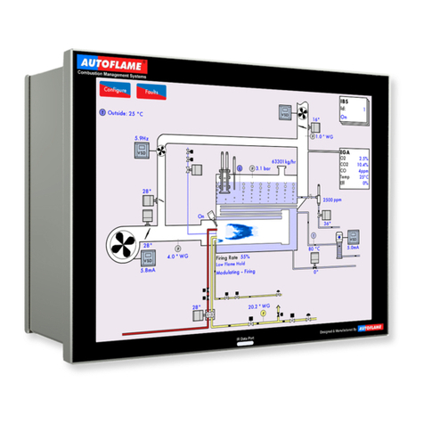
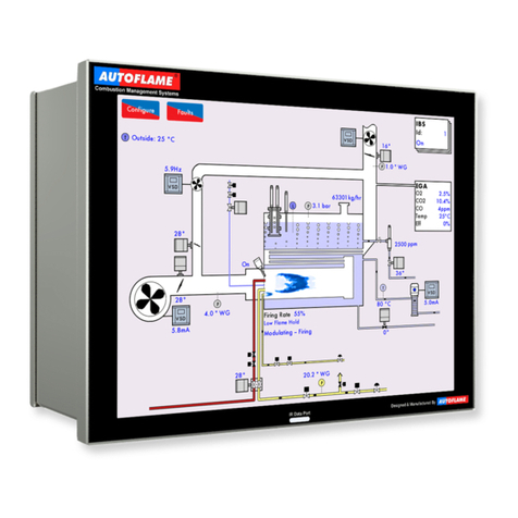
The home screen shown in Figure 3.1.i displays the current boiler setup. It provides operation
information for each component of the burner/boiler in real time. Pressing on components will display
further information e.g. pressing on the servomotor image will show the servomotor position history.
This boiler room setup can be configured to display what is actually on site, please see section 3.19.5
Boiler Room Configuration.
22.05.2017 Mk8 MM End User Guide Page 9

3 End User Operation
3.1.1 Home Screen Components
Servomotor Variable
speed drive
Flame
scanner Oil pressure
sensor
Air pressure
sensor/
boiler steam
pressure
detector
Gas pressure
sensor
Boiler
temperature
detector/
outside
temperature
sensor
Feed water
temperature
sensor
Main fuel
valve open Main fuel
valve closed
Pilot gas
valve open
Pilot gas
valve closed
Control fuel
valve open
Control fuel
valve closed
Main gas
regulator Pilot gas
regulator
Gas flowing
No gas
flowing
Oil flowing
No oil
flowing
Combustion
air fan
Induced
draught fan
Gas flame Oil flame
#
Capacitance
probes
2nd Low
conductivity
probe
External level
sensor for
water level
Steam
header
TDS probe Feed water
pump
Page 10 Mk8 MM End User Guide 22.05.2017

3 End User Operation
IBS
Information
Three Pass
Fire Tube
22.05.2017 Mk8 MM End User Guide Page 11

3 End User Operation
3.1.2 Faults
Figure 3.1.2.i Lockouts
Press in the Home screen to view the faults, which are categorised into lockouts, errors,
alarms, warning and first out alarms, and are access by pressing on the corresponding tabs.
Fault Type Shuts Down Burner Reset By
Lockout Burner control fault Yes Reset button or input on T56
Error Internal or hardware fault Yes Power cycle
Alarm Critical system fault Yes Reset button or input
Warning Non-critical fault No Reset button
First out Configurable fault Optional Reset button/ auto
Page 12 Mk8 MM End User Guide 22.05.2017

3 End User Operation
3.2 Status Screen
3.2.1 Status
Figure 3.2.1.i Status
Press on the boiler load detector or the boiler image in the Home screen (Figure 3.1.i) to display the
Status screen, which gives the following information:
Burner rating
Current fuel selected and type
Burner starts and run hours
Current firing rate
Control method – internal PID control, external modulation or DTI/remote firing rate
Actual temperature/pressure reading from load detector
Current setpoint – required, reduced, DTI or external
Stat status – running interlock T53/ internal stat
Burner switch on/off offset
Reduced setpoint
Indication if MM is firing to meet required or reduced setpoint (red = active, grey = inactive)
Arrows for adjusting setpoint
Press the arrows to change the required or reduced setpoints. If these arrows are not
displayed, then either the user setpoint change has been disabled (option 15), the DTI is controlling the
setpoint (option 16), external setpoint is enabled (parameter 72), or OTC is enabled (option 80).
Note: Use parameters 29 and 30 to adjust the load detector reading if required.
22.05.2017 Mk8 MM End User Guide Page 13

3 End User Operation
3.2.2 Status – History
Figure 3.2.2.i Status – History
Press in the Status screen in Figure 3.2.1.i to show the Status History. The setpoint, actual
temperature/pressure and firing rate are displayed graphically.
This data is logged for 24 hours on the MM. Use the buttons to change the timescale of the
data displayed, and press and drag on the axis to zoom in/out of the graph.
This information is logged for 2 years on the DTI when connected with the MM.
Note: Power cycling the MM or changing fuel will reset the 24 hour history data log on the MM.
Page 14 Mk8 MM End User Guide 22.05.2017

3 End User Operation
3.2.3 Status – Burner Enable/Disable
Figure 3.2.3.i Status – Burner Enable/Disable
Press and hold for 3 seconds in the Status screen in Figure 3.2.1.i to disable the burner.
Press and hold this same button to enable the burner.
22.05.2017 Mk8 MM End User Guide Page 15
Other manuals for Mk8 MM
3
Table of contents
Other AUTOFLAME Controllers manuals
