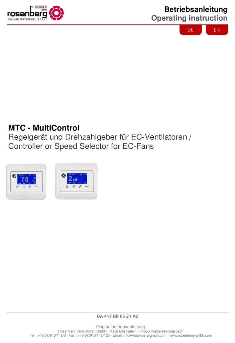
Rosenberg H42 Series Technical manual

1
Operation Instruction
BA 415 AB 07/15/A/ Release 1
Rosenberg Ventilatoren GmbH ·Maybachstraße 1 ·74653 Künzelsau-Gaisbach
Tel.: +49(0)7940/142-0 ·Fax.: +49(0)7940/142-125 ·Email: info@rosenberg-gmbh.com ·www.rosenberg-gmbh.com
EN
Suprabox User Terminal
Ventilation control
for SupraBox COMFORT 800 to 5000

2

3
1 Index
1 Index 3
2 General Information 4
3 Safety 4
4 Definition of Qualified Personnel 5
5 Normal Operation / Scope of validity 5
5.1 Normal operation 5
5.2 Scope of validity 5
6 Description 6
6.1 Technical Data 7
6.2 Terminal configuration 7
6.3 Scope of delivery of the Control System 8
7 Installation 8
7.1 Assembly / Initiation 9
7.2 Lead Colours 10
7.3 Identification of Electric Accessories 10
8 Brief Instruction 11
8.1 Key Configuration 11
8.2 Main display 12
8.3 Switch On/Off the Unit 14
8.4 Menu-Overview 14
8.5 Setting the Temperature 16
8.6 Setting of the Fan intensity 17
8.7 Activating the automatic operation 18
8.8 Alarm Display, Alarm Message and Warnings 20
8.9 Unit settings, initial operation 23
8.10 Language Settings 24
8.11 Time and Time Programs 24
8.12 Manufacturer Information, Service information and System information 26
8.13 Real value display (Status I/O) 28
8.14 USB- Port for Software Update 29
8.15 Optional accessories 30
9 Service Menu 33
9.1 Enter the service menu 33
9.2 Working hours 33
9.3 Alarm Memory 33
9.4 Bus connection 34
9.5 Guided Setup 34
9.6 Manual operation 41
9.7 Setup Menu 41
10 Parameter list 42
11 Storage, Transport 45
12 Maintenance, Servicing 45
13 Accessories and Field devices 45
14 Copyright 48
15 Customer Service, Manufacturer’s address 49
16 Initial Operation Report 50
17 Notes 51

4
2 General Information
This operating manual contains important technical and safety information.
Read this operating manual carefully before unpacking, mounting, commissioning and for other
maintenance and service activities on the control device.
It must be ensured that the operating manual is accessible and available during the operation of the
ventilation unit type SupraBox COMFORT (SBC).
An operator of the electronic must read the operating manual carefully and understand the infor-
mation before unpacking, mounting, commissioning and for other maintenance and service activities
on the control device.
If there are further questions regarding installation, operation or maintenance please consult our
sales department.
3 Safety
The following icons show certain hazards or give advice for the save operation.
Caution! Danger zone! Safety advice!
Hazardous electricity or high voltage!
Caution! Hot surface!
Important advice, Information
This unit carries hazardous electric current and controls rotating, mechanical parts.
Death, grave physical harm or substantial damage to property may occur, if the in-
structions of the operation manual are not observed.
Only qualified pers
onnel
should work on the units. These personnel must be familiar
with all warning instructions and actions to install and use the unit according to the
manual. The successful and safe operation of the unit is dependent on the correct
transport, assembly use and maintenance.
Do not install the unit in places with current conducting dust, corrosive or flammable
gases, humidity, rain or excessive heat or pollution.
SupraBox COMFORT Control is not protected against explosion (Directive 94/9/EG).

5
It is strictly forbidden to perform work on live electrical equipment. Protection rating
of the open unit is IP21! Contact with dangerous voltage is possible.
The unit operates with alternating current. The current level must correspond to the
value on the name plate. The suprabox Comfort and the integrated switch cabinet
must be closed during the operation.
Repairs may only be made by specialists authorized by Rosenberg Ventilatoren
GmbH. Only replace circuit breakers, do not repair or bridge them. Only use fuses
which are indicated in the wiring diagram. Check the zero-potential using a bipolar
voltage tester.
The wiring of the
Supra
B
ox
COMFORT
Controller
or the assembly with the article
number H42-73****must be carried out according to the connection schematic.
Wrong connections lead to the destruction of the unit. Deficiencies of electrical in-
stallations/assemblies/equipment must be repaired immediately. If there is imminent
danger do not operate the unit/assembly in defective condition.
4 Definition of Qualified Personnel
According to the operation manual and the warning instructions, qualified personnel are persons who
are familiar with installation, assembly, initialization and operation of the product and have the follo
w-
ing qualifications
:
-
Training or instruction i.e. authorization to switch power and equipment on and off, to ground
and to mark circuits and devices according to the standards of safety engineering.
-
Training or briefing in maintenance and use of appropriate safety equipment according to the
standards of safety engineering.
-
Training in first aid.
5 Normal Operation / Scope of validity
5.1 Normal operation
The Controller or the assembly with the article number H42-73**** optionally equipped with an
interface-card is exclusively developed and intended for the tasks as control, regulation and monitor-
ing for the Rosenberg ventilation unit Supra Box COMFORT (SBC). Other uses or uses above their
intended use are prohibited unless contractually agreed upon. The manufacturer is not liable for
damages which might occur by use of the product for something other than its intended purpose.
The user assumes all risks.
It is part of the intended use to obey the operations described in this manual for the
assembly, operation and maintenance.
We point out that this operation manual is only valid for the device and not for the
complete installation!
5.2 Scope of validity
The scope of validity of this manual includes the following control versions or the assembly
with the article number H42-73****:
-temperature and ventilation for SupraBox COMFORT (SBC) for series 800-5000

6
6 Description
The control units or the assembly with the article number H42-73**** have been specially con-
structed for the control of Rosenberg Ventilatoren GmbH compact appliance series Suprabox Com-
fort (SBC) and represent the epitome of convenience, safety of use, control and maintenance of
the equipment. The control units are produced according to the German VDE guidelines and meet
the requirements of the valid EG-regulation (DIN EN 60204-1 and others).
The following functions are included in the control system and can be activated if necessary:
•Temperature control of the supply air and room temperature respectively for the use of
PWW register and systems (pump warm water)
EEH systems (single-stage electrical heating)
PKW register and systems (pump cold water)
•Temperature control of the supply air and room temperature respectively for the use of di-
rect evaporator and systems with on-site interface boards for example CompTrol Interface
III (Producer Mitsubishi / Stulz) of PAC IF011B (producer Mitsubishi)
•Temperature control of the supply air and room temperature respectively for the use of
set-point compensation according to the outside temperature conditions in winter and
summer and taking into account the energetic temperature conditions, cool-night air func-
tion, Mixed air function, Standby mode
•Temperature control of the supply air and room temperature respectively for the use of
heat recovery system
PWT countercurrent plate heat exchanger system
RWT rotary heat exchanger system
•Temperature control of the supply air and room temperature respectively for the use of
Fresh air and return air dampers
•Automatic mode with step less control and monitoring of the EC-Fans
•Automatic mode with control of the fans and operation with the help of a selectable de-
mand sensor (speed, volume flow, pressure)
•Overriding of the fans upon requests by external switch contact or a selectable demand
sensor (Temperature, humidity, CO2, VOC)
•Airflow monitoring
•External running mode and collective fault signal
•Program sequence for defrosting / de-icing of the heat recovery, preheating
•Anti-Blocking protection for the pump PWW- (pump warm water) and PKW- (pump cold
water) system
•Anti-Freeze protection for PWW- (pump warm water) system
•Overheating control EEH- System
•Automatic mode with adjustable weekly program with 6 switching times and 3 profiles per
weekday
•Automatic mode with indication of the actual value, state and alarm, alarm memory, man-
ual activation of the outputs
•Loading of the program routine via USB- Interface
•Room operating device with simple settings on the program routine
•Communication- Interface card with different transmission protocol (Modbus, Bacnet)
•Display German and English

7
6.1 Technical Data
Nominal voltage: AC 230/400V 50Hz (+6% / -10%)
Control voltage: AC 24V 50Hz,
disconnected galvanically from the mains
voltage
Ambient temperature
Operating device and
-20°C to +60°C max. 90%r.F.
IP protection type of the external operat-
ing device
IP40 for wall mounting / IP65 for front mount-
ing
Wire connection from the control to the
operating device
Li9YY6 not crossed with RJ 11 Telephone
plug,
10m cable enclosed
length max.: 50m (without TCONN6J000)
Conductor NYM-J 3x2,5mm²
Maximum power of the alarm relay
AC 250V 10A for 1,5mm2core cross-section
The alarm relay energizes as soon as the Suprabox COMFORT (SBC) is live.
In case of an alarm or the interruption of the voltage supply the relay de-energizes.
6.2 Terminal configuration
The terminal configuration has to be performed exclusively according to the valid wiring.
The electric potentials must be observed when mounting and wiring. Incorrect wiring
may damage the electronic circuit or lead to wrong logically program routine.
If after reading the operating instructions and the circuit diagram there are still some
questions regarding installation, operation or maintenance please contact the Rosen-
berg Ventilatoren GmbH.

8
6.3 Scope of delivery of the
Control System
•Control:
Controller Item Number H42-00400 with connecting plug Item Number H42-
00401
or the complete assembly Item number H42-73**** integrated in the Ventilation
Unit SupraBox COMFORT (SBC)
•Operation and display:
Control panel Item number H42-00104 or H42-00102, to be connected with
the Controller via
connecting cable
•Connecting cable:
10m flat cable Item number TF5-20012 with 2 pieces tab connectors Item
number TF5-20011, pre-assembled
•Operating instructions Doc. No. BA 415 AA 09/14/A/ Edition 1, updated edi-
tion
•Circuit documentation, circuit diagram
•Program Routine SupraBox COMFORT is already loaded in the Controller
7 Installation
- Check the rightness of the the article number of all delivered components from
the assembly control and the ventilation unit SupraBox COMFORT (SBC) with
the delivery note date, the technical data and the planning data in the circuit di-
agram. Damages and costs due to mistakes can be avoided.
- Unpack the components and check for damages. Damages shall be reported
immediately to the supplier or the manufacturer Rosenberg Ventilatoren GmbH.
Damaged and defected components or assemblies must not be put into opera-
tion.
Read operation manual and safety instructions carefully. Please note the safety
symbols on the ventilation unit SupraBox COMFORT (SBC). Take care that
every user of the SupraBox COMFORT reads the operation manual before ini-
tiation. The operation manual must be accessible to everybody.
- The unit may not be installed in places with current conducting dust, corrosive
or flammable gases. Protect the control and operating device from humidity,
rain or heat.
- The control is operated with alternating current voltage. Obey the instructions
on the type plate of the ventilation unit SupraBox COMFORT (SBC).
- Electrical installation of the equipment, the mains voltage and the external op-
erating devices must be made according to the valid circuit diagram. The elec-
trical potential must be observed during the wiring. Incorrect wiring can cause
permanent damage to the electronic or lead to wrong logical program routine.
- Electrical connection may only be made by an authorized electrician according
to the German VDE regulations and the instructions of the local electrical power
supplier in your region. Connection must be made exactly according to the cir-
cuit diagram and the configuration diagram. Check all screw joints and retighten
them if necessary.
- The main switch fixed at the control terminal of the SupraBox COMFORT (SBC)
must be freely accessible. The phases must be connected to the main switch.
- The consumers (fans, pumps) as well as control units (actuators, valve actua-
tor) can with conventional cables are wired which is sufficient for the current
carrying capacity and thermal load.

9
- The collective alert contact is a changeover contact, which displays malfunc-
tions of the equipment. The relay is energized, if there is voltage supply and no
malfunction. In case of alarm message, the relay will de-energize and keep this
status until the malfunction is repaired and the current alert will be acknowl-
edged at the operating device.
7.1 Assembly / Initiation
Preparing the SupraBox COMFORT (SBC) for initial operation:
Proper mechanical assembly
Electric connection according to instructions
Remove foreign particles in the suction and exhaust area and in the
complete SupraBox COMFORT (SBC)
Please observe the necessary normative, regulations and directives
(for example EN 60204-1) for a continuous protective conductor sys-
tem, for equipotential banding and for automatic switch-off of the
supply voltage to avoid dangerous situations.
Check the supply cables before assembly if there is absence of tension
after you have saved the the electrical protection against reactivation. The
ventilation unit leads after connecting to the supply line dangerous elec-
trical tension and controls rotating mechanical parts.
Assembly the electrical components only when the mechanical ventilation
system parts are permanently installed on their intended place.
The fans must rotate completely smoothly and without jolt at every motor
speed.
The control and the electrical accessories must be connected according
to the connection diagram. Faulty connections will cause destruction of
the unit.
The user i
s bound to operate the devices only in proper working cond
i-
tion. Danger zones which can exist between the Rosenberg Ventilatoren
GmbH units and installations on the customer side must be safeguarded
by the user!

10
7.2 Lead Colours
Main current: Control wire:
L1 ⇒black N ⇒blue 24V AC ⇒red 24V DC ⇒violet
PE ⇒yellow/green 24V AC ⇒red-white 24V DC ⇒violet-white
External
voltage
/ Alarm relays orange
The isolation of the individual electrical conductor (strand) is performed in the shown colours for the purpose of
labelling.
7.3 Identification of Electric
Accessories
Code letter Type of Accessories Examples
A Assemblies Amplifier as assembly
B Converter Measuring converter, microphone
C Capacities Condenser
D Memory, delay device UND-link, magnetic tape recorder
E Miscellaneous Light, heating
F Protection equipment Fuse, actuator
G Generators, power supply Machine generator, oscillator
H Annunciator Signal unit
K Relays, contactors Auxiliary contactor, main contactor
L Inductors Coil
M Motors Polyphase motor, direct current motor
N Amplifier Measuring amplifier
P Measuring amplifier Voltmeter
Q High voltage current devices Circuit breaker, automatic interrupter
R Resistors Thermal resistor
S Switch, selector Key, rotary switch
T Transformers Voltage transformer
U Modulators Frequency converter
V Tubes, semi-conductors Diodes, Transistors
W Transmission Cables, waveguides
X Clamps Socket-Outlet
Y Electric mechanics Break
Z Escape, Filter, Balance Compandor
The integral components complete assembly Art. No. H42-73**** integrated in the ventilation unit SupraBox
COMFORT (SBC) are like the labeling in the circuit documentation (circuit diagram).

11
8 Brief Instruction
The
Contro
ller
restarts after the supply voltage is switched on and
shows the
main display with the supply temperature and the plant status.
If within 60s no keystroke is recognized, the display changes from every sub-
menu automatically back to the main display.
8.1 Key Configuration
Image: Operation and main display
Key [ALARM]
Flashes red if an error occurred.
Displaying of the upcoming alarms by operation
Acknowledging of eliminates interferences after operation
Returning to the main display after operation
Key [Prg]
Selection of the menu-overview and the main-menu pages by operation
Key [Esc]
Returning to the menu-overview and the main-display by operation
When operating during a change of values of parameters it will switch to the higher level (menu-
overview-display). There is no guarantee that the previous parameter value remains.
Key [Up]
Arrow key
„up“
Change the display in the menu-overview and for the in-and output sides by operation
Changing or raising a parameter value (setting value) for the value adjustment

12
Key [Down]
Arrow key
„down“
Change the display in the menu-overview and for the in-and output sides forward or down-
wards by operation
Changing or reducing a Parameter value (setting value) for the Value adjustment
Key [Enter]
Arrow key
„middle“
Choosing of the current adjustable parameter value for processing after operation
Confirming the current adjustable parameter value after processing after operation
On and Off switch of the program routine or the controller or the ventilation unit by a continuing
actuation (only for displaying in the main display)
8.2 Main display
Main display
Display for the supply temperature in °C
The current measurement of the sensor will automatically be updated and displayed.
Display for the room or return temperature in °C following the selection
Selection for displaying the control temperature in the programming level > commissioning >
Temperature control
The current measurement of the sensor will automatically be updated and displayed.
Display for the plant status. The possible text are:
Status OFF, Status ON, Status START-UP, Status SUPPORT, Status PRE-HEAT, Status
COOL RECOVER, Status DEFROST, Status STOP RUN, Status ALARM, Status
OVERDRIVE, Status AUTO-OFF
Key [Enter]
Arrow key
„middle“
Automatic operation
On and Off switching of the program routine or the control or ventilation unit by a con-
tinuing actuation
Key [Prg]
Selection of the Menu-Overview and the menu pages by operation
From the main display you can go while pressing the [Prg]key to the main menu

13
Automatic operation:
The automatic operation can be manually activated by pressing the [Enter] key or through the
time program or with an extern switch or through an optional accessory zone operating device.
This functions can be deselected in the display Menu-Overview at Settings

14
8.3 Switch On/Off the Unit
Key [Enter]
Arrow key „mid-
dle“
Automatic operation
On and Off switching of the program routine or the control or the ventilation unit by a con-
tinuing actuation for display of the main display.
Automatic operation:
The automatic operation can be manually activated by pressing the [Enter] key or through the
time program or with an extern switch or through an optional accessory zone operating device.
This function can be deselected in the display Menu-Overview > Settings
Additional information in the chapter optional accessories.
8.4 Menu-Overview
Main menu
Password request
Key [Prg]
From the main display you can go to the main menu with the key [Prg]
Selection of the Menu-Overview and the menu pages by operation

15
Key [Up]
Arrow key „up“
Key [Down]
Arrow key
„down“
To be used to switch between the display or in the main menu, or to scroll.
The possibilities to be chosen are:
1 = Settings
2 = Status I/O
3 = Time schedule
4 = Date, time
5 = System info
6 = Language
7 = Program
To be used to adjust the password at the password entry level
Key [Enter]
Arrow key
„middle“
Selection of the menu group
Switching in the selected input and output sides
Switching to the selected program levels with the password request
Password Level Service = 0077
Password Level Service and Unit configuration = 0123
The password will be reset after a selected time.
Service menu after the password request
Key [Up]
Arrow key „up“
Key [Down]
Arrow key
„down“
To be used to switch between the display or in the main menu, or to scroll.
The possibilities to be chosen are:
1 = Hours counter
2 = Alarm history
3 = Communication

16
Key [Enter]
Arrow key
„middle“
Selection of the menu group
Switching in the selected input and output sides
Switching to the selected program levels with the password request
8.5 Setting the Temperature
Set point to Menu-Overview > Settings
The temperature set point can be set manually in the menu Settings. The input value is the
manual set point for the comfort temperature to heat and cool.
By pressing the key [Enter] while Setting is marked the display for temperature set point on the
electronic controller is called.
Key [Up]
Arrow key „up“
Key [Down]
Arrow key
„down“
In the display changes or increase/reduce of the parameter value:
Key [Enter]
Arrow key
„middle“
In the display: Choosing of the current adjustable parameter value for operation
The Cursor / pointer jumps on the setting value manual temperature value-set point.
Confirming of the current changed parameter value setting value manual temperature set point.

17
The display of the room-/return temperature in °C is made upon selection or
setting of the control temperature for the Temperature-Set point:
The selection takes place in the programming level > initial operation > Temperature control
The current measurement of the sensor will be automatically displayed and updated.
8.6 Setting of the Fan intensity
The ventilation intensity can be set in the menu settings. The display can be shown or
hidden according to the settings during the initial operation. The entries are manual set
point standards for the supply air and the return air fan.
Speed set point setting scaled in %
to find at Display Menu-overview >
Settings
Speed set point setting scaled in Pa
to find at Display Menu-Overview >
Settings
Speed set point setting scaled in m3/h
to find at Display Menu-Overview >
Settings
By pressing the key [Enter] while setting is marked the display for air volume
or ventilation intensity on the electronic control can be seen. The display is in
the display list of the settings. With the key [Up] or the key [Down] you can
switch to the display bellow.
The display of the setting for the fan operation can be chosen with the de-
faults programming level > Initial operation> Fan setting
Key [Up]
Arrow key „up“
Key [Down]
Arrow key „down“
In the display changes or increase/reduce of the parameter value:

18
Key [Enter]
Arrow key „middle“
In the display; Choose the current adjustable parameter value for operation
The Cursor / pointer jumps to the setting value manual temperature value-set
point.
Confirming of the current changed parameter value setting value manual
temperature set point.
During the automatic operation the ventilation intensity will be automatically
calculated. A distinction is made here between two variants:
1. If there is an external sensor for moisture measurement, air quality
measurement or pressure measurement with a 0-10 V out, the sensor value
is applied in order to determine the optimal ventilation demand. The volume
flow measurement takes place with the connected sensors and the installed
air tubes. With the default setting volume flow the automatic mode can be
set with selected sensor or sensor values.
2. The used sensors for the automatically modification of the ventilation
intensity can be from the type temperature, humidity, air quality VOC and
CO2concentration. The larger the current temperature deviation the more is
ventilated. The Fans were operated therefore in three stages.
See also chapter activating the automatic operation (release according to
the default in the programming level)
Other setting values in the display programming level >initial operation
>Fan settings.
8.7 Activating the automatic
operation
The ventilation intensity, external running mode, the activation of the
time program, the back-up mode and night air can be set in the menu
settings.The display can be shown or hidden according to the set-
tings during the initial operation.
By pressing the key [Enter] while the settings are marked, one of the display
below the electronic controller can be invoked. The display is in the display
list of the settings. With the Key [Up] or Key [Down]you can switch to the
display bellow.
3. During the automatic operation the ventilation intensity will be auto-
matically calculated. By selecting, the control type will be activated or
deactivated for operation of the fans. The used sensors for the auto-
matically modification of the ventilation intensity can be from the type
temperature, humidity, air quality VOC and CO2concentration. The
larger the current temperature deviation the more is ventilated. The
fans were operated therefore in three stages.
Other setting values in the display programming level >initial operation >Fan set-
tings.
The automatic operation can be activated through an external switch or key
with adjustable operation time per program routine. The activation of the sig-
nal contact or signal input at the electronic controller is activated by the
choice or deactivated by deselection. If the weekly program is activated, the
configured times and set points were used. Other setting values in the dis-
play Menu-Overview>time program. Standards issued by the manufacturer
are in the display program level >initial operation>comfort function.

19
The user has the possibility to activate the internal time program of the
electronic controller.
Through a selection the weekly program is activated or by deselection
deactivated. If the weekly program is activated, the configured times
and set point were selected. Further setting values in the display
Menu-Overview>time program.
Activating the back-up mode heating or cooling.
The menu is displayed only with connected room temperature sensor
and release heating or cooling.
At the back-up mode heating the adjustable temperature should not be
reduced also at inoperative status of the unit. At the back-up mode cool-
ing the adjustable temperature should n
ot be reduced also at inoperative
status of the unit. The unit automatically switches on when the adjusta-
ble limiting values were exceeded. The unit runs in the back-up mode at
least for the time set. Set the limit values and the maturities in the pro-
gramming level at >Program level > initial operation >comfort function
Activating of the function night air by using the energetic Temperature-
Potential. The menu is displayed only for connected external-and room
sensors.
Certain temperature condition allows in summer an air exchange in the
room at night. When during the day a high temperature has heated up
the room and at night a cooling of the room temperature with cool out-
side air takes place. The outdoor temperature at night must be higher as
the set value so that in the cool season an exchange with too cool air
can be excluded. At the same time, the room temperature must have at
least one set value, so that the room does not cool down through the air
exchange. An adjustable minimum value as difference between room
and outdoor temperature prevents not efficient ventilation through air ex-
change. If all premises are given the ventilation runs for the minimum
term. The function is only permitted with a connected room and outdoor
temperature sensor. Setting of the limit value and terms in the program
level at >Program level> initial operation>comfort function
Key [Up]
Arrow key „up“
Key [Down]
Arrow key „down“
In the display changes or increase/reduce of the parameter value:
Key [Enter]
Arrow key „middle“
In the display; Choose the current adjustable parameter value for operation
The Cursor / pointer jumps to the setting value manual temperature value-
set point.
Confirm the current changed parameter value setting value Menu-Overview
> Settings

20
8.8 Alarm Display, Alarm Mes-
sage and Warnings
An alarm message will be generated, when the return and supply air fan
reports a disruption. The fault signal relay from the fan-electronic starts a
signal contact to the controller; see circuit documentation or circuit diagram.
The fault signals relay on the return and supply air fan delay after
switching on the voltage activation. Usually the fault signal relay in the
fan electronic is assembled in the factory. In event of an exchange the
setting must be verified with the Rosenberg Software EC-Param.
Possible disruptions can be :
Locked rotor,
Overheating of the electronic,
Overheating of the Motor,
Overcurrent,
Power supply under voltage, Overvoltage,
Over speed,
Error power electronics
An alarm message will be generated, when the return and supply filter is
dirty (the maximum pressure deviation of the return filter)
A dirty filter must be replaced. Replacement parts can be ordered at Rosen-
berg Ventilatoren GmbH.
The limit value can be adapted in the program level.
A smoke alarm or signal contact to a central fire alarm system/a fire pro-
tection flap can be connected to the Suprabox Comfort. The behavior in
case of alarm can be adjusted on startup of the unit. After the alarm is
acknowledged, the Suprabox Comfort continues normal operation.
The water heater is supplied with a capillary contact, which opens in case
the frost protection temperature falls below the minimum level. After that the
mixing valve of the heating coil will be totally opened, the circulating pump
started, the fans stopped and the external air damper closed. When the ca-
pillary contact closes, the unit re-starts after a certain time which can be
determined. After the frost protection alarm is tripped three times (within 2h)
the unit is stopped until it is manually restarted at the operator panel. Before
the manual restart the cause of the alarm must be verified. The SupraBox
COMFORT (SBC) starts again the normal operation when the disruption at
the signal input is no longer recognized.
Three internal temperature sensors are integrated in the unions of the Su-
prabox Comfort for the measurement of return air, fresh air (during the oper-
ation of the Suprabox Comfort) and to measure the temperature after the
heat recovery. An alarm is initiated in case that one or several sensors are
incorrectly connected or defective. In case of error the unit will be stopped
until it is acknowledged.
This manual suits for next models
4
Table of contents
Other Rosenberg Controllers manuals
Popular Controllers manuals by other brands

Cirrus Logic
Cirrus Logic Crystal LAN CS8900A Application note

Atmel
Atmel AT91 ARM Thumb Application note

VAC
VAC V200P Installation, operation and maintenance instructions

Neptronic
Neptronic TM100N Specification & installation instructions

Danfoss
Danfoss ERC 113 Reference manual

CNC
CNC AC-CNC2017-2S operating instructions

Omron
Omron E5EK DEVICENET user manual

CHINT
CHINT NS2-80 User instruction

Lennox
Lennox VRF F1943L-3P Product specifications

Danfoss
Danfoss VLT Option Panel instruction manual

Dwyer Instruments
Dwyer Instruments DHII Digihelic II Series Specifications-installation and operating instructions

Hobby
Hobby Biotherm II Operating instruction