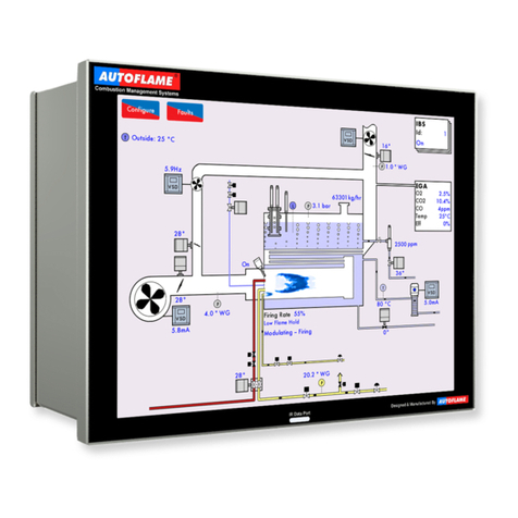
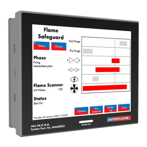
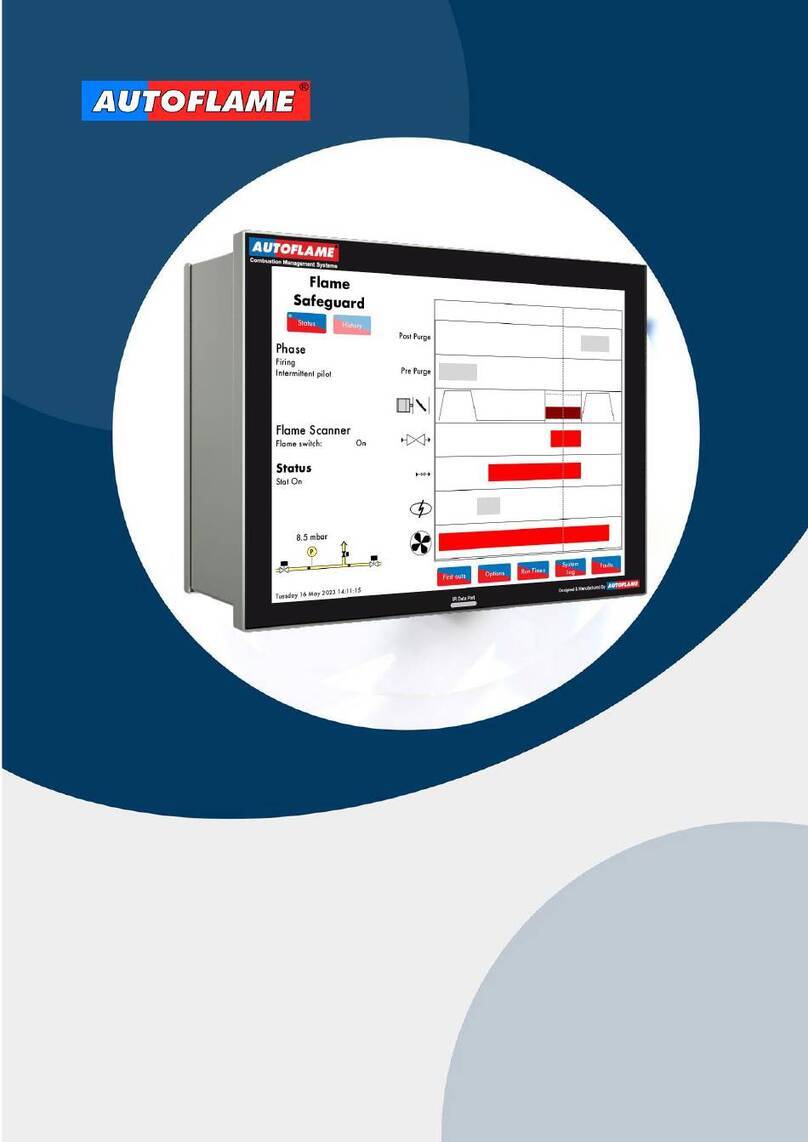
AUTOFLAME Mk8 MM User manual

Mk8 MM
Expansion Features
Installation and
Commissioning Guide


Mk8 MM
Expansion Features
Installation and Commissioning Guide
Issued by:
AUTOFLAME ENGINEERING LTD
Unit 1-2, Concorde Business Centre
Airport Industrial Estate, Wireless Road
Biggin Hill, Kent TN16 3YN
Tel: +44 (0)845 872 2000
Fax: +44 (0)845 872 2010
Email: [email protected]
Website: http://www.autoflame.com/
Registered Holder:
Company:
Department:
This manual and all the information contained herein is copyright of
Autoflame Engineering Ltd. It may not be copied in the whole or part without
the consent of the Managing Director.
Autoflame Engineering Ltd’s policy is one of continuous improvement in both
design and manufacture. We therefore reserve the right to amend
specifications and/or data without prior notice. All details contained in this
manual are correct at the time of going to print.


Important Notes
A knowledge of combustion related procedures and commissioning is essential before
embarking work on any of the M.M./E.G.A. systems. This is for safety reasons and
effective use of the M.M./ E.G.A. system. Hands on training is required. For details on
schedules and fees relating to group training courses and individual instruction, please
contact the Autoflame Engineering Ltd. offices at the address listed on the front.
Short Form - General Terms and Conditions
A full statement of our business terms and conditions are printed on the reverse of all
invoices. A copy of these can be issued upon application, if requested in writing.
The System equipment and control concepts referred to in this Manual MUST be installed,
commissioned and applied by personnel skilled in the various technical disciplines that
are inherent to the Autoflame product range, i.e. combustion, electrical and control.
The sale of Autoflame’s systems and equipment referred to in this Manual assume that
the dealer, purchaser and installer has the necessary skills at his disposal. i.e. A high
degree of combustion engineering experience, and a thorough understanding of the
local electrical codes of practice concerning boilers, burners and their ancillary systems
and equipment.
Autoflame’s warranty from point of sale is two years on all electronic systems and
components.
One year on all mechanical systems, components and sensors.
The warranty assumes that all equipment supplied will be used for the purpose that
it was intended and in strict compliance with our technical recommendations. Auto-
flame’s warranty and guarantee is limited strictly to product build quality, and design.
Excluded absolutely are any claims arising from misapplication, incorrect installation
and/or incorrect commissioning.

Contents
1TECHNICAL SPECIFICATIONS ................................................................................... 1
1.1 Mk8 Expansion Board.............................................................................................................1
1.2 Expansion Board Inputs and Outputs ......................................................................................2
1.2.1 Fuse Ratings.....................................................................................................................2
1.3 Cable Specifications ................................................................................................................3
1.4 Expansion Board Terminals Description ..................................................................................4
2EXPANSION OPTIONS ............................................................................................ 7
3WATER LEVEL CONTROL ........................................................................................ 25
3.1 Overview.............................................................................................................................. 25
3.1.1 Safety ........................................................................................................................... 25
3.1.2 Autoflame Water Level Control .................................................................................... 25
3.1.3 Water Treatment........................................................................................................... 26
3.2 Water Valve ......................................................................................................................... 27
3.2.1 Specifications................................................................................................................ 27
3.2.2 Feed Water Valve Sizing.............................................................................................. 28
3.2.3 Feed Water Control...................................................................................................... 29
3.3 Ways of Level Sensing.......................................................................................................... 30
3.3.1 Overview ...................................................................................................................... 30
3.3.2 Configuration................................................................................................................ 31
3.4 Capacitance Probes.............................................................................................................. 35
3.4.1 Overview ...................................................................................................................... 35
3.4.2 Operation..................................................................................................................... 36
3.4.3 Specification ................................................................................................................. 36
3.4.4 Installation Safety Guidelines ....................................................................................... 39
3.4.5 Capacitance Probe – Externally Mounted Pots ............................................................ 40
3.4.6 Capacitance Probe – Internally Mounted Pots ............................................................. 42
3.4.7 Capacitance Probe – Installation for a Water Tube Boiler ........................................... 44
3.4.8 External Probe Chamber Dimensions ........................................................................... 45
3.4.9 Configuration................................................................................................................ 46
3.5 2nd Low Probe........................................................................................................................ 47
3.5.1 Overview ...................................................................................................................... 47
3.5.2 Operation..................................................................................................................... 48
3.5.3 Specifications................................................................................................................ 48
3.5.4 Installation and Safety Guidelines ................................................................................ 50
3.5.5 Configuration................................................................................................................ 51

3.6 External Level Sensor ........................................................................................................... 52
3.7 Auxiliary Alarm Inputs.......................................................................................................... 53
3.8 Commissioning Procedure .................................................................................................... 54
3.8.1 Commissioning Checks.................................................................................................. 54
3.8.2 Levels............................................................................................................................ 54
3.8.3 Setting End of Probe Level............................................................................................ 55
3.8.4 Setting 2nd Low Level ..................................................................................................... 57
3.8.5 Setting 1st Low Level...................................................................................................... 58
3.8.6 Setting Control Point Level ............................................................................................ 59
3.8.7 Setting HIGH Level ....................................................................................................... 60
3.8.8 Save Commissioning..................................................................................................... 61
3.8.9 Operational Checks...................................................................................................... 63
3.8.10 Adjust Control Point ...................................................................................................... 64
3.9 Water Level Control Functions.............................................................................................. 65
3.9.1 Pre-Alarms .................................................................................................................... 65
3.9.2 Pump Bypass................................................................................................................. 65
3.9.3 Test Outputs and Shunt Switch...................................................................................... 66
3.9.4 Sudden Pressure Drop .................................................................................................. 67
3.10 Faults .................................................................................................................................... 68
4TOP BLOWDOWN ................................................................................................. 71
4.1 Overview.............................................................................................................................. 71
4.1.1 Importance of Maintaining TDS.................................................................................... 71
4.1.2 TDS, Conductivity and Temperature ............................................................................. 72
4.2 TDS Valve ............................................................................................................................. 73
4.3 TDS Probe............................................................................................................................. 74
4.3.1 Specification ................................................................................................................. 74
4.3.2 Dimensions.................................................................................................................... 75
4.3.3 Installation .................................................................................................................... 76
4.3.4 Configuration................................................................................................................ 77
4.4 Ways of Controlling TDS Level ............................................................................................. 78
4.4.1 Continuous TDS Control................................................................................................ 78
4.4.2 Solenoid and Servomotor 2-State TDS Control............................................................. 78
4.4.3 TDS Timing Diagram ..................................................................................................... 79
4.4.4 Sample Routine............................................................................................................. 80
4.5 Calibrating TDS Probe .......................................................................................................... 81
4.6 Faults .................................................................................................................................... 83
5BOTTOM BLOWDOWN.......................................................................................... 84

5.1 Overview.............................................................................................................................. 84
5.2 Bottom Blowdown Reduction ................................................................................................ 85
5.2.1 Blowdown Savings........................................................................................................ 85
5.2.2 Calculation for Bottom Blowdown Reduction................................................................ 86
5.3 Installation Guidance............................................................................................................ 88
5.3.1 Bottom Blowdown Valve............................................................................................... 88
5.3.2 Bottom Blowdown Module ........................................................................................... 89
5.4 Set-up.................................................................................................................................... 92
5.4.1 Bottom Blowdown Settings............................................................................................ 92
5.4.2 Setting Servomotor ....................................................................................................... 93
5.5 Bottom Blowdown Configuration .......................................................................................... 97
5.5.1 Bottom Blowdown Log .................................................................................................. 99
5.6 Faults .................................................................................................................................. 100
6DRAUGHT CONTROL ........................................................................................... 101
6.1 Overview............................................................................................................................ 101
6.1.1 Benefits of Draught Control ........................................................................................ 101
6.1.2 Fully Integrated Draught Control................................................................................ 101
6.2 Draught Control Operation ................................................................................................ 103
6.2.1 Overview .................................................................................................................... 103
6.2.2 Deactivation Window ................................................................................................. 103
6.2.3 Draught Control Trim .................................................................................................. 105
6.3 Set-Up ................................................................................................................................. 107
6.3.1 Configuration.............................................................................................................. 107
6.3.2 Ways of Using Draught Servomotor........................................................................... 108
6.4 Commissioning Draught Control ......................................................................................... 109
6.4.1 Commissioning Checks................................................................................................ 109
6.4.2 Commissioning Screen................................................................................................ 110
6.5 Faults .................................................................................................................................. 111
7REMOTE CONTROL .............................................................................................. 112
7.1 Overview............................................................................................................................ 112
7.2 Configuration...................................................................................................................... 113
7.3 Modbus Addresses ............................................................................................................. 114
8FIRST OUTS ......................................................................................................... 123
8.1 Overview............................................................................................................................ 123
8.2 Configuration...................................................................................................................... 124
8.2.1 Running Interlock Circuit ............................................................................................. 124
8.2.2 Interlock Option.......................................................................................................... 128

9HEAT FLOW......................................................................................................... 129
9.1 Overview............................................................................................................................ 129
9.1.1 Benefits of Steam/Hot Water Flow Metering.............................................................. 129
9.1.2 Configuration.............................................................................................................. 129
9.2 Steam Flow Metering.......................................................................................................... 130
9.2.1 Steam Flow Calculation .............................................................................................. 130
9.2.2 Steam Flow ................................................................................................................. 134
9.2.3 Steam Flow with Economiser ...................................................................................... 135
9.2.4 Steam Flow with Deaerator ........................................................................................ 136
9.2.5 Steam Flow with Deaerator and Feed Sensor ............................................................ 137
9.3 Hot Water Flow Metering................................................................................................... 138
9.3.1 Hot Water Flow Calculation ....................................................................................... 138
9.3.2 Hot Water Flow .......................................................................................................... 140
9.3.3 Hot Water Flow with Economiser................................................................................ 141
9.4 Faults .................................................................................................................................. 142
10 FULLY METERED COMBUSTION CONTROL ............................................................ 143
10.1 Overview............................................................................................................................ 143
10.1.1 Introduction................................................................................................................. 143
10.1.2 Importance of Excess Air ............................................................................................ 143
10.2 Fully Metered Combustion Control Operation ................................................................... 144
10.2.1 Philosophy .................................................................................................................. 144
10.2.2 Firing Rate .................................................................................................................. 144
10.2.3 Control Process........................................................................................................... 145
10.2.4 Mass Flow Meters....................................................................................................... 146
10.2.5 Volume Flow Meters ................................................................................................... 146
10.3 Set-Up ................................................................................................................................. 147
10.3.1 Configuration.............................................................................................................. 147
10.3.4 Limitations ................................................................................................................... 148
10.3.5 Commissioning............................................................................................................ 149
10.4 Faults .................................................................................................................................. 153


1 Technical Specifications
04.09.2016 Mk8 MM Expansion Features Installation and Set-Up Guide Page 1
1 TECHNICAL SPECIFICATIONS
1.1 Mk8 Expansion Board

1 Technical Specifications
Page 2 Mk8 MM Expansion Features Installation and Set-Up Guide 04.09.2016
1.2 Expansion Board Inputs and Outputs
Outputs: 120/230 V All outputs with the exception of PF are switched neutrals
BFW 250mA Must be connected through contactor
BB 250mA Must be connected through contactor
HWV 100mA (alarm indicator)
2LA 100mA (alarm indicator)
2LV 100mA (alarm indicator)
H1A 100mA (alarm indicator)
1LV 100mA (alarm indicator)
79 100mA (alarm indicator on MM board)
TB 250mA Solenoid only, must be connected through contactor
PF Maximum 2A (load currents for above terminals)
Note: Max number of alarm indicators on at any time is 3 (1LV, 2LA, 2LV)
Main Voltage Signal Inputs:
At 120V current loading is approximately maximum 0.7mA per input.
At 230V current loading is approximately maximum 1.5mA per input.
1.2.1 Fuse Ratings
Fuse Rating Spare Part Number
1 6.3A (T) FU10026
Fuse 1 protects the mains input to the MM, including the mains output terminals 50 – 64.
2 2A (T) FU10034
Fuse 2 protects the power supply (terminal 69) for the servomotors, alarm and 2 port valve. If this
fuse blows, the error ‘Triac Power Supply Error (Check F2)’ will occur.
3 500mA FU10040
Fuse 3 protects the 13.5V power supply to the oil pressure sensor and IR scanner on terminal 49. If
this fuse blows, the error ‘Fused 13.5V Supply Error (Check F3)’ will occur.
4 500mA 500mA
Fuse 5 protects the power supply (terminal PF) for the expansion servos and alarm outputs. If fuse
5 blows, the error ‘Expansion PF Output (Check F5)’ will occur.
5 2A (T) FU10034
Fuse 5 protects the power supply (terminal PF) for the expansion servos and alarm outputs. If fuse
5 blows, the error ‘Expansion PF Output (Check F5)’ will occur.
6 2A FU10027
Fuse 6 protects the DC circuits. If this fuse blows, the display will be off and both LEDs adjacent to
fuse 7 and 8 will be off.
7 4A FU10050
Fuse 7 protects the internal 5V supply. If this fuse blows the display will be off and the LED
adjacent to the fuse will be off.
8 2.5A FU10042
Fuse 8 protects the internal 12V supply. If this fuse blows the display will be off and the LED
adjacent to the fuse will be off.

1 Technical Specifications
04.09.2016 Mk8 MM Expansion Features Installation and Set-Up Guide Page 3
1.3 Cable Specifications
High/ Control Voltage
Screened cable should not exceed 10m and unscreened cable should not exceed 1m. The ionisation/
flame rod cable must be shielded to prevent interference with other cables, as it is a high voltage and
high frequency signal.
Low Voltage
The screened cable used from the MM to the servomotors and detectors must conform to the following
The screened cable used for low voltage wiring from the MM to the servomotors, detectors and
variable speed drive must conform to the following specification:
16/0.2mm PVC insulated overall braid, screened, PVC sheathed.
Sixteen wires per core
Diameter of wires in each core 0.2mm
Rated at 440V AC rms at 1600Hz
DEF 61-12 current rating per core 2.5A
Maximum operating temperature 70oC (158oF)
Nominal conductor area 0.5sq mm per core
Nominal insulation radial thickness on core 0.45mm
Nominal conductor diameter per core 0.93mm
Nominal core resistance at 20oC. 40.1Ω/1000m
Nominal overall diameter per core 1.83mm
Fill factor of braid screen 0.7
Equivalent imperial conductor sizes 14/0.0076
Use the number of cores suitable for the application. A universal part numbering system appears to
have been adopted for this type of cable as follows:
16-2-2C 2 Core
16-2-3C 3 Core
16-2-4C 4 Core
16-2-6C 6 Core
(5 Core not readily available)
Note: If using 4 Core cable and interference is detected, use 2 sets of 2 Core.
Data Cable
Data cable must be used for connections between MMs for sequencing applications and between MMs
and EGAs and for connection between MMs and DTI
Types of data cable that can be used:
1 Beldon 9501 for 2-core shielded cable (1 twisted pair)
2 Beldon 9502 for 4-core shielded cable (2 twisted pairs)
3 STC OS1P24
Samples are available upon request. Low voltage and data cable can be ordered directly from
Autoflame Engineering, please contact Autoflame Sales.

1 Technical Specifications
Page 4 Mk8 MM Expansion Features Installation and Set-Up Guide 04.09.2016
1.4 Expansion Board Terminals Description
S All terminals marked S are internally connected. They are provided for connections
to the various screened cables.
P- 0V supply to top blowdown and feed water servomotors
FW Signal from feed water servomotor, indicating position
P+ +12V supply to top blowdown and feed water servomotors
- Common for terminals T1, T2 and T3
T1 Signal input from T1 temperature sensor
T2 Signal input from T2 temperature sensor
- Common for terminal T1, T2 and T3
T3 Signal input from T3 temperature sensor
TW Signal from top blowdown servomotor, indicating position
F- Common for terminals MF and CF
MF Current input, 4-20mA for cold water make up flow meter
CF Current input, 4-20mA for condensate return flow meter
I+ Current output, 4-20mA to feed water VSD
V+ Voltage output, 0-10V to feed water VSD
IV- Common for terminals I+ and V+
EX- Common for terminal EX+
EX+ Current input, 4-20mA for external water level probe or fuel flow feedback
DT+, DT- Digital communications from draught control pressure sensor
DP- 0V supply to draught control pressure sensor and draught control servomotor
DP+ +12V supply to draught control pressure sensor and draught control servomotor
DPW Signal from draught control servomotor, indicating position
5T+, 5T- Digital communications from bottom blowdown module and 2nd low probe
4P- 0V supply to 2nd low resistance probe
4P+ +12V supply to 2nd low resistance probe
6T+, 6T- Communications port connections I/O module RS485
3P+ +9V supply to TDS probe

1 Technical Specifications
04.09.2016 Mk8 MM Expansion Features Installation and Set-Up Guide Page 5
3P- 0V supply to TDS probe
3T+, 3T- Digital communication connections from TDS probe
1P+ +9V supply to capacitance probe 1
1P- 0V supply to capacitance probe 1
1T+, 1T- Digital communications connections from capacitance probe 1
2P+ +9V supply to capacitance probe 2
2P- 0V supply to capacitance probe 2
2T+, 2T- Digital communications connections from capacitance probe 2
FO1 First Out annunciation line voltage input 1
FO2 First Out annunciation line voltage input 2
FO3 First Out annunciation line voltage input 3
FO4 First Out annunciation line voltage input 4
FO5 First Out annunciation line voltage input 5
FO6 First Out annunciation line voltage input 6
FO7 First Out annunciation line voltage input 7
FO8 First Out annunciation line voltage input 8
FO9 First Out annunciation line voltage input 9
FO10 First Out annunciation line voltage input 10
FO11 First Out annunciation line voltage input 11
FO12 First Out annunciation line voltage input 12
PF Power feed 2A output (230V/110)
FO13 First Out annunciation line voltage input 13
FO14 First Out annunciation line voltage input 14
FO15 First Out annunciation line voltage input 15
HAI External high water auxiliary input
1AI External 1st low water auxiliary input
2AI External 2nd low water auxiliary input
M/R System alarm mute/reset
TST System test alarm inputs/ shunt switch

1 Technical Specifications
Page 6 Mk8 MM Expansion Features Installation and Set-Up Guide 04.09.2016
NC Unused – do not connect
TB Switched neutral – top blowdown contactor
TBI Switched neutral – drives top blowdown servomotor clockwise
1LV Switched neutral – 1st low water visual alarm
H1A Switched neutral – 1st low/ high water audible alarm
2LV Switched neutral – 2nd low water visual alarm
2LA Switched neutral – 2nd low water audible alarm
HWV Switched neutral – High water visual alarm
BB Switched neutral – Bottom blowdown contactor
BFW Switched neutral – Feed water pump contactor
MVI Switched neutral – drives feed water servomotor clockwise
MVD Switched neutral – drives feed water servomotor counter clockwise
TBD Switched neutral – drives top blowdown servomotor counter clockwise
DCI Switched neutral – drives draught control servomotor clockwise
DCD Switched neutral – drives draught control servomotor counter clockwise

2 Expansion Options
04.09.2016 Mk8 MM Expansion Features Installation and Set-Up Guide Page 7
2 EXPANSION OPTIONS
The Options, Parameters and Expansion Options must only be changed by factory
trained and certified technicians who have a thorough appreciation of the Autoflame
combustion systems and the combustion process in general. Any person changing these
settings without the correct factory training and understanding of the boiler plant may
place themselves and others in a potentially dangerous situation.
CH1, CH2, CH3, CH4, CH5, CH6 and CH7 refer to the rows of buttons respectively
start with CH1 at the top.
The options, parameters and expansion options are all viewable while the MM is in run mode. In
commissioning mode, all of the options, parameters and expansion options can be adjusted according
to the application. Non safety-critical options, parameters and expansion options can be adjusted
through Online Changes.
Press in the Commission Mode screen to access the Expansion Options. Any number of
expansion options can be changed at on time. By pressing WLC, TBD, BBD, DC, Modbus FO and Flow
at the bottom of the screen, the expansion options can be grouped together by feature.
When the changes have been made to suit the application’s needs, press Exit to go back to the
Commission Mode screen.
To set all the options, parameters and expansion options to the default values and erase the
commissioning data, set option/ parameter 160 to 5. The MM will then automatically restart.
Note: The Expansion Feature must be unlocked by sending the code for that MM via
Download Manager. Please see PC Software Guide on unlocking Expansion Features.
Unlockable Software Feature Part Number
Autoflame Water Level MK8001
Analogue Water Level (requires Autoflame Water Level) MK8002
Top Blowdown MK8003
Bottom Blowdown MK8004
Draught Control MK8005
Direct Modbus MK8006
First Out Annunciation MK8007
Fully Metered Combustion System MK8008
Heat Flow (Steam Flow + Hot Water Flow) MK8009

2 Expansion Options
Page 8 Mk8 MM Expansion Features Installation and Set-Up Guide 04.09.2016
Exp
Option Default Range Description
1 0 Water Level Control Function
Expansion feature 1 must be unlocked on the MM For setting 1, there must
be a minimum of two level sensing elements or a conflict will appear. For
the possible water level sensing device combinations, please see section
3.3. The capacitance probes with/without external level sensor will be
commissioned at end of probe, second low, first low, control point and high
water.
0 Water level control disabled
1 Water level control enabled
2 0 Feedwater Control Element
The feedwater pump will turn on and off at the according to the levels set
relative to the control point, through expansion options 10, 11 and 12. For
setting 0, water going to the boiler is only controlled by the feedwater
pump output terminal BFW. For settings 1 and 2 the MM controls the
feedwater via a PID loop, see expansion options 13, 14, 15, and 16. For
setting 1 the MM uses the servomotor on terminals P-, FW, P+, MVI and
MVD. For setting 2 the MM uses the VSD on terminals I+, V+ and IV-.
0 Pump on/off only
1 Pump on/off and servomotor control
2 Pump on/off and VSD control
3 0 Capacitance Probes
If water level control is enabled, the MM will require a minimum of two
level sensing elements. For the possible water level sensing device
combinations, please see section 3.3.
0 Capacitance probes disabled
1 One capacitance probe
2 Two capacitance probes
4 0 External Level Sensor
The external level sensor is wired to terminals EX- and EX+ and will give a
4-20mA signal. The readings can be scaled in expansion options 30 and
31. If an external level sensor is used, then a 4-20mA signal for fuel flow
feedback cannot be enabled (option 57) and fully metered combustion
control cannot be enabled (expansion option 140). For the possible water
level sensing device combinations, please see section 3.3.
0 Disabled
1 Enabled
5 0 Auxiliary Alarm Inputs
For setting 1, the auxiliary alarm mains inputs terminals HAI, 1AI and 2AI
are used in addition to the capacitance probes with/without external level
sensor readings. For the possible water level sensing device combinations,
please see section 3.3.
0 Auxiliary alarm inputs disabled
1 Auxiliary alarm inputs enabled
6 0 Second Low Probe
For setting 0, it is recommended that an auxiliary second low mains input is
wired to terminals 2AI. For setting 1, the Autoflame conductive second low
probe is wired to terminals 4P-, 4P+, 6T- and 6T-. Please see local codes/
regulations for second low probe and auxiliary second low alarm setup.
For the possible water level sensing device combinations, please see
section 3.3.
0 Second low probe disabled
1 Second low probe enabled

2 Expansion Options
04.09.2016 Mk8 MM Expansion Features Installation and Set-Up Guide Page 9
Exp
Option Default Range Description
7 0 Pre-High Alarm Percentage
The pre-high alarm level is at percentage between the control point and
high water, with the control point being referring to 0% and the high water
referring to 100%. For setting 0 there is no pre-high alarm and for settings
higher than 1, the MM will generate an alarm if the water level reaches this
% value between the commissioned control point and high water. For
example, if this is set to 45%, then a pre-high alarm will occur if the water
level rises to 45% between the control point and high water level.
0 Disabled
1 – 99 1% - 99%
8 0 Pre-First-Low Alarm Percentage
The pre-first-low alarm level is at percentage between the control point and
first low, with the control point being referring to 0% and the first low
referring to 100%. For setting 0 there is no pre-first-low alarm and for
settings higher than 1, the MM will generate an alarm if the water level
reaches this % value between the commissioned control point and first low.
For example, if this is set to 45%, then a pre-first-low alarm will occur if the
water level drops to 45% between the control point and first low level.
0 Disabled
1 – 99 1% - 99%
9 0 Burner Operation at High Water
For setting 0, the burner will continue to fire at high water. For setting 1 the
burner will stop firing at high water. Expansion option 10 sets whether the
pump turns off above the control point or high water.
0 Burner runs at high water
1 Burner stops at high water
10 0 Pump Turn Off Point
The water level at which the pump turns off is set as a percentage above
the control point for setting 0, or above the high water for setting 1, see
expansion option 11.
0 Pump turns off above control point
1 Pump turns off above high water
11 30 Pump Turn Off Percentage
When the water level reaches this percentage of the control point or high
water, depending on how expansion option 11 is set, the pump will turn
off. If expansion option 11 is set to 0, then this percentage will be between
the control point and high water. If expansion option 11 is set to 1, then
then this percentage is above high water, and should not be set more than
a safe top of the probe level.
0 – 100 0% - 100%
12 10 Pump Turn On Percentage
When the water level dro
p
s the control
p
oint, the
p
um
p
will turn on
at this percentage in between the control point and first low.
0 – 100 0% - 100%

2 Expansion Options
Page 10 Mk8 MM Expansion Features Installation and Set-Up Guide 04.09.2016
Exp
Option Default Range Description
13 50 Feedwater Control Proportional Band
The proportional band is set as a percentage between the control point and
first low where the PID control will make corrections to the feedwater going
to the boiler to maintain the control point. The feedwater control will act on
servomotor or VSD depending on how expansion option 2. The control
point represents 0% and first low represents 100%, so it is possible to set
the feedwater control proportional band to a water level below the first
low. If the water level is outside of the proportional band, then the
feedwater servomotor will remain fully open.
0 Disabled
1 – 200 1% - 200%
14 20 Feedwater Control Integral Time
The integral element in the feedwater control will make corrections to the
feedwater via the servomotor or VSD, depending on expansion option 2.
For a slower response, increase the integral time. For a quicker response in
critical steam applications to avoid the water level reaching first low,
decrease the integral time. However if overshoot occurs and the water level
rises to above the control point and this is not desired, then the derivative
element will need to be enabled, see expansion option 15.
0 Disabled
1 – 1000 Seconds
15 0 Feedwater Control Derivative Time
The derivative element in the feedwater control is suitable for applications
requiring a quick response but the water level should not rise too high
above the control point. For example, if the burner is set to stop firing at
high water in expansion option 9 and high water is commissioned not too
far above from control point, then overshoot is undesirable in a critical
steam application, as the burner would stop firing.
0 Disabled
1 – 1000 Seconds
16 900 Feedwater Servo Open Angle
The feedwater servomotor closed position is set by zeroing the
potentiometer in commissioning mode. As default the servomotor is set as
fully open, however this setting can be decreased to shorten the
operational movement range of the servomotor.
100 – 900 10.0O– 90.0O
17 0 Pump Bypass Operation
The pump bypass (terminal TB) will turn on at the switch point set as a % of
the open range of the valve, and will turn off at an offset from the switch
point, set as the bypass hysteresis, see expansion options 18 and 19.
However if the pump is turned off, then the pump bypass will also be turned
off. For setting 1, the pump bypass hysteresis is below the switch point, so
the pump bypass will turn off at an offset below the switch point. For setting
2, the pump bypass hysteresis is above the switch point, so the pump
bypass will turn off at an offset above the switch point.
0 Pump bypass disabled
1 Pump bypass on above switch point
2 Pump bypass on below switch point
18 20 Pump Bypass Switch Point
The bump bypass switch point is set as a percentage of the valve open
range set in expansion option 16.
5 – 95 5% - 95%
Other manuals for Mk8 MM
3
Table of contents
Other AUTOFLAME Controllers manuals
