AutoGate 2490 Guide

FWI-0001-A –RIGHT ANGLE GEARMOTOR FIELD REPLACEMENT INSTRUCTIONS
READ INSTRUCTIONS PRIOR TO STARTING
REQUIRED TOOLS: Workbench or other suitable flat work surface, tape measure, 9/16” wrench, 9/16” socket, 10mm
socket, ratchet, 1/8” hex key, two (2) 2x4 wood blocks approximately 9 inches long, 2” x 4” x 1/8” spacer plate or any
other flat wide tool, pen or pencil and paper.

FWI-0001-A –RIGHT ANGLE GEARMOTOR FIELD REPLACEMENT INSTRUCTIONS
Parts Included in this kit:
#8 –4 pcs. M6 x 1 x 40mm carriage bolt
#9 –4 pcs. M6-1.0 nylon lock nut
#10 –4 pcs. 1” flat washer – 18-8 SS
#20 –1 pc. Gear motor –24v / 90 GC

FWI-0001-A –RIGHT ANGLE GEARMOTOR FIELD REPLACEMENT INSTRUCTIONS
1.) Lock the gate in the open or closed position using the T/M Safety Pin (see the operator details page (#10) in the
installation and operation manual or contact AutoGate.
Example: CLOSED position
2.) Remove four (4) “Tek” screws retaining the operator top panel then remove the top panel.
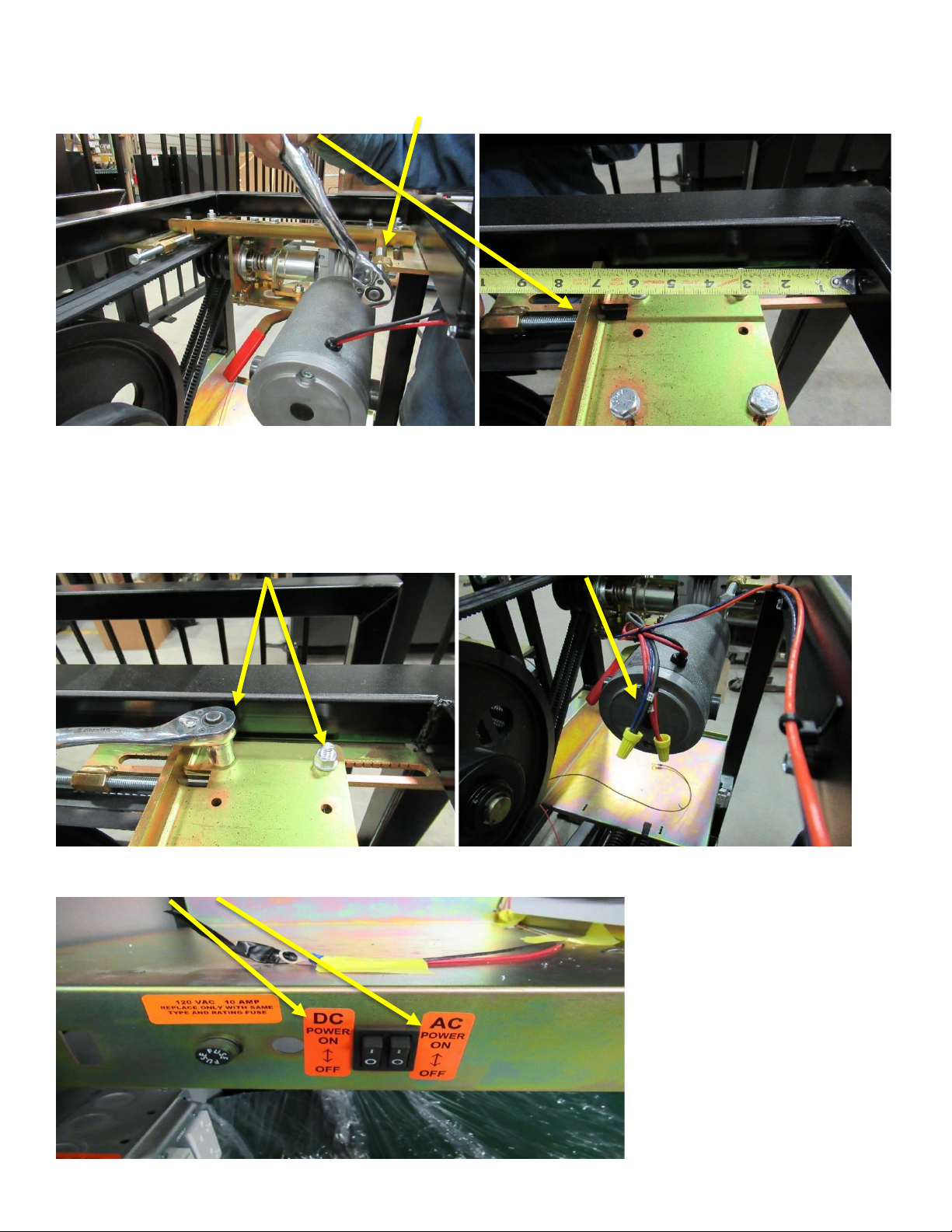
3a.) Turn off the DC and AC power switches. 3b.) Disconnect the motor power wires.
3c.) LOOSEN the four (4) 3/8-16 hex nuts (DO NOT REMOVE at this Time).
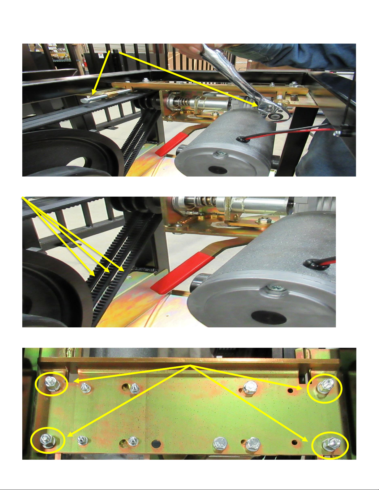
FWI-0001-A –RIGHT ANGLE GEARMOTOR FIELD REPLACEMENT INSTRUCTIONS
3d.) Remove two (2) 3/8-16 Belt Tension bolts.
3e.) Remove three (3) Drive Belts.
3f.) Remove ALL four (4) 3/8-16 hex nuts, four (4) 3/8” split lock washers, and four (4) 3/8-16 carriage bolts.
FWI-0001-A –RIGHT ANGLE GEARMOTOR FIELD REPLACEMENT INSTRUCTIONS
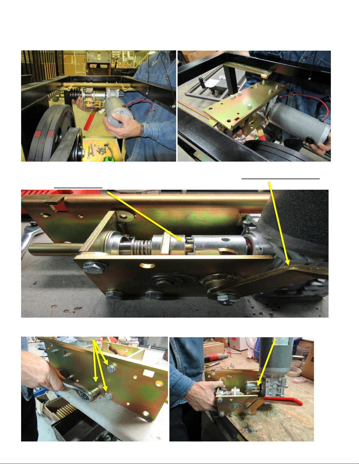
4.) Lift the Motor Assembly and move it toward the center of the operator then lower the Motor Assembly out of the
operator and place on a workbench or other suitable work surface.
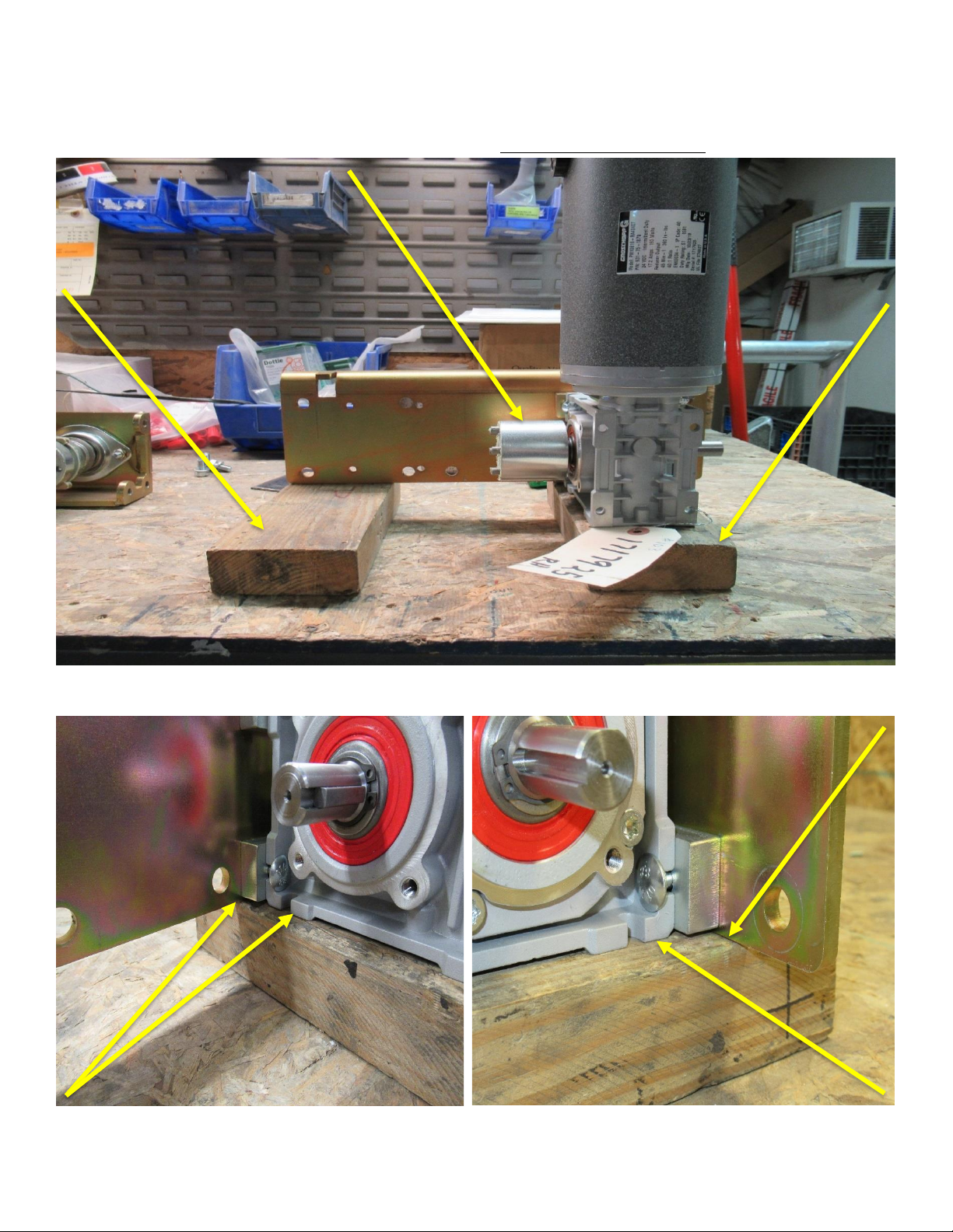
5.) Orient the Motor Assembly as shown (RH model shown, LH opposite). Using the 90 DM Retractor Cam Handle
Position the RAD Slide Coupler in the open position.
6.) Remove three (3) 3/8-16 bolts securing the RAD Bearing Mounting Bracket then remove the assembly.
FWI-0001-A –RIGHT ANGLE GEARMOTOR FIELD REPLACEMENT INSTRUCTIONS
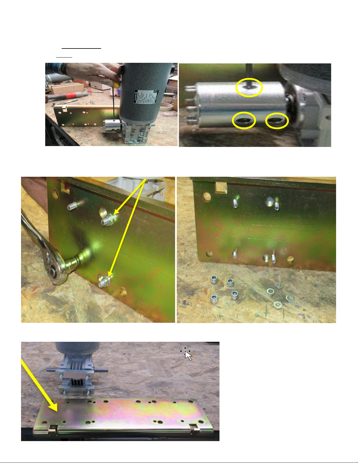
7.) Loosen, but do not remove three (3) set screws securing the RAD Fixed Coupler to the gearbox shaft then remove
the coupler. (retain for use on the replacement motor and gearbox assembly)
8.) Remove and discard four (4) M6-1.0 nylon hex nuts and four (4) M6 x 12mm flat washers used to retain the motor
and gearbox assembly to the mounting plate.
9.) Remove mounting plate. (Retain)
FWI-0001-A –RIGHT ANGLE GEARMOTOR FIELD REPLACEMENT INSTRUCTIONS
10a.) Remove and retain two (2) spacer blocks
10b.) Remove and discard four (4) M6-1.0 x 40mm carriage bolts. They can be difficult to remove and may have to be cut
off.
11.) Place the replacement motor and gearbox assembly on a work bench or other suitable work surface
12a.) Insert four (4) supplied M6-1.0 x 40mm carriage bolts into the slots on the motor and gearbox assembly.
12b.) Place two (2) retained spacers on the four (4) M6-1.0 x 40mm carriage bolts

FWI-0001-A –RIGHT ANGLE GEARMOTOR FIELD REPLACEMENT INSTRUCTIONS
12c.) Install the Mounting Plate onto the replacement motor and gearbox assembly
12d.) Install four (4) (supplied) M6 x 12mm flat washers and four (4) supplied M6-1.0 nylon hex nuts, (do not tighten
them.)
FWI-0001-A –RIGHT ANGLE GEARMOTOR FIELD REPLACEMENT INSTRUCTIONS
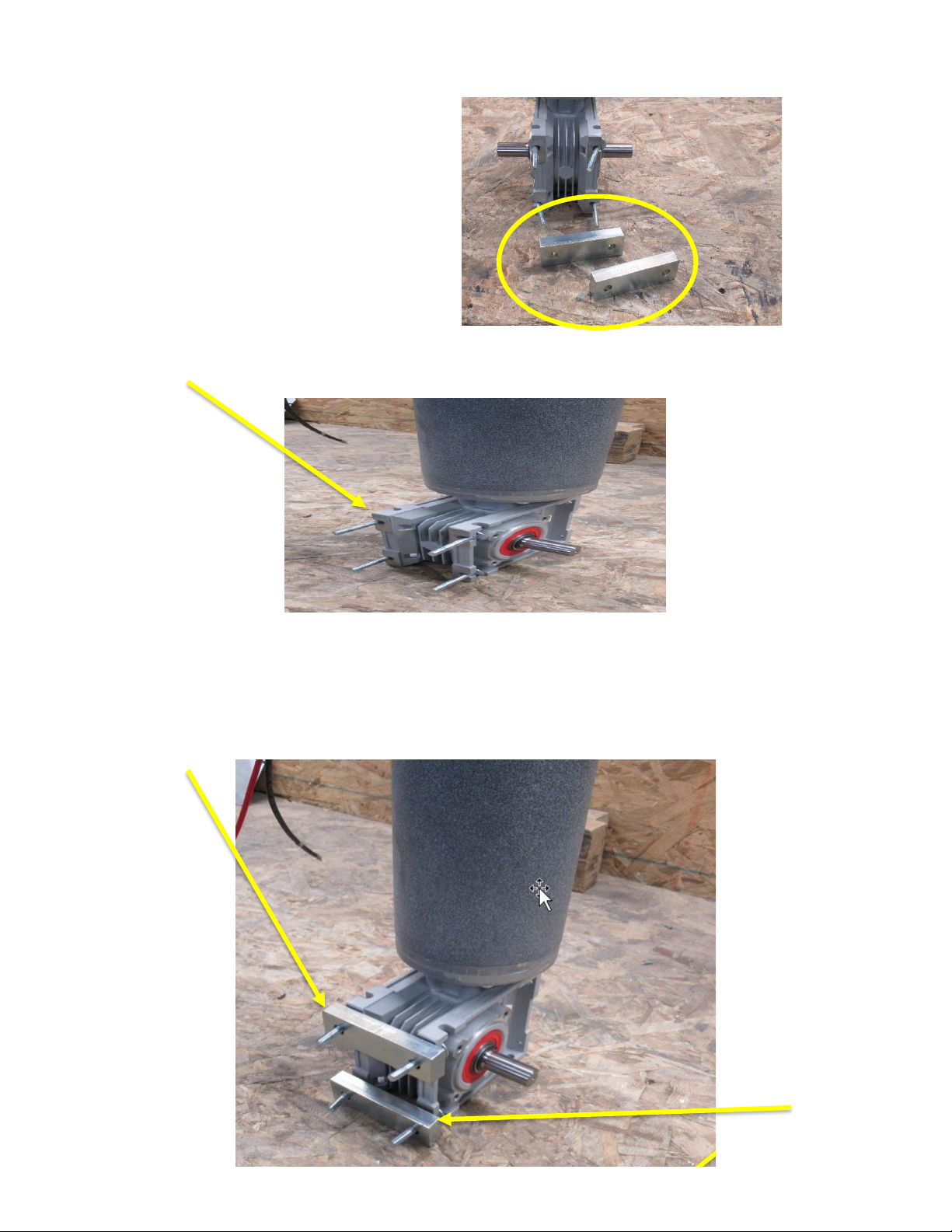
13a.) Place two (2) wood blocks on a workbench or other suitable work surface
13b.) Place the new motor and gearbox assembly and mounting plate on the wood blocks
13c.) Install the RAD Fixed Coupler on to the gear box shaft but do not tighten the set screws
14.) Ensure the motor and gear box assembly and the plate are fully seated on the wood blocks (no gaps present)

FWI-0001-A –RIGHT ANGLE GEARMOTOR FIELD REPLACEMENT INSTRUCTIONS
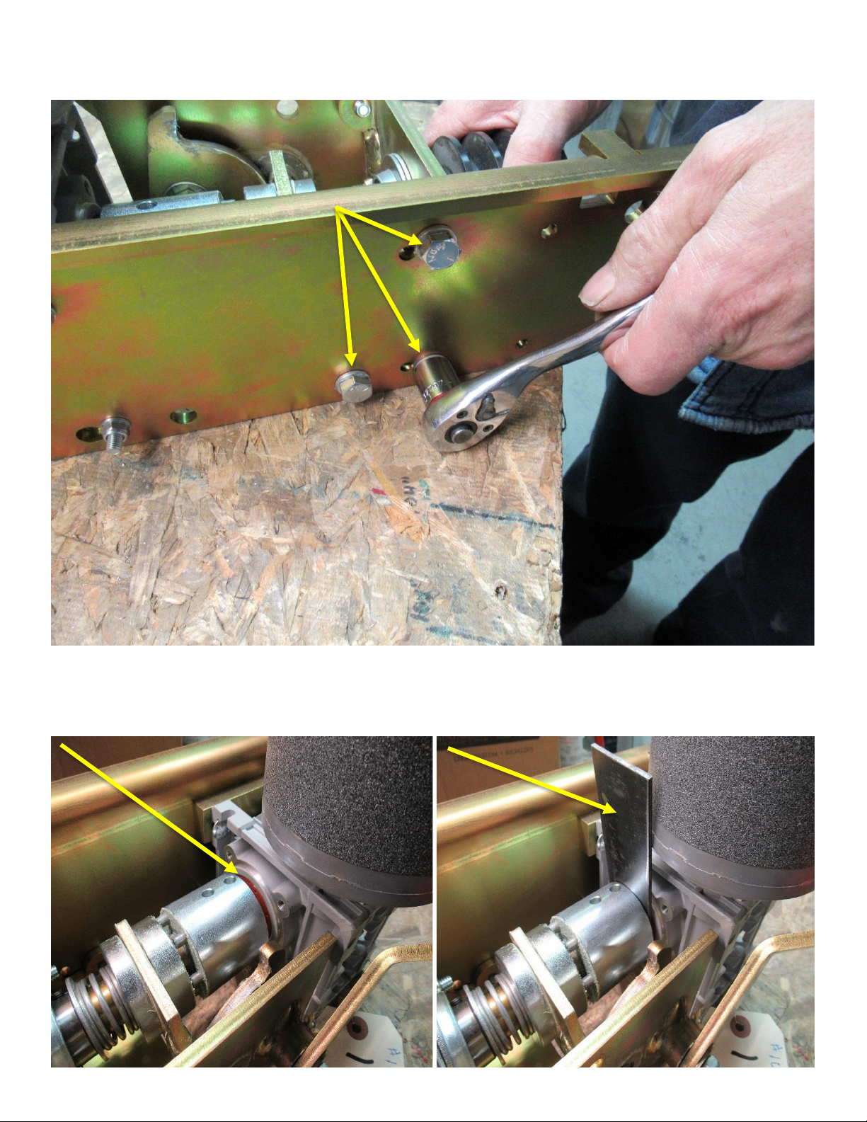
15.) Tighten four (4) M6-1.0 nylon hex nuts (ensure the mounting plate and gearbox stay seated against wood blocks)
16a.) Install the RAD Bearing Mounting Bracket assembly ensuring the pilot end of the RAD 1” Main Drive Shaft is
seated into the bearing in the RAD Fixed Coupler.
FWI-0001-A –RIGHT ANGLE GEARMOTOR FIELD REPLACEMENT INSTRUCTIONS
16b.) Secure the RAD Bearing Mounting Bracket assembly with three (3) 3/8-16 bolts
17.) Insert the 2” x 4” x 1/8” spacer plate or other flat wide tool between the gearbox and RAD Fixed Coupler and push
the fixed coupler toward the RAD Slide Coupler to ensure the RAD 1” Main Drive Shaft is fully seated in the bearing then
tighten the set screw/screws that are visible.
FWI-0001-A –RIGHT ANGLE GEARMOTOR FIELD REPLACEMENT INSTRUCTIONS
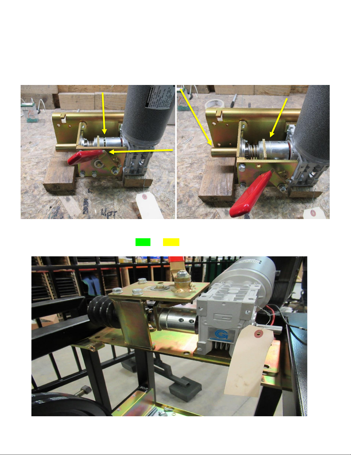
18a.) Close the RAD Slide Coupler using the 90 DM Retractor Cam Handle. Turn the shaft, by hand, until the RAD Slide
Coupler closes fully then inspect for a gap between the two (2) couplers. If a gap is present repeat steps 18 and 19 until
the gap is no longer present.
18b.) Open the RAD Slide Coupler, turn the shaft then close the RAD Slide Coupler. Turn the shaft until the RAD Slide
Coupler closes fully then inspect for a gap between the two (2) couplers. Repeat this step 3 to 4 times checking for gaps
each time. If a gap is present repeat step 18 and 19 until the gap is no longer present.
19.) Place the Motor Assembly on top of the slide side plates. Reconnect the motor power wires. Turn the AC and DC
power switches on. Run the motor using the OPEN and CLOSE buttons on the control board. As the motor runs, observe
the couplers and ensure there is no wobble and/or gaps. Repeat steps 18 –20 to eliminate all wobble and/or gaps.
FWI-0001-A –RIGHT ANGLE GEARMOTOR FIELD REPLACEMENT INSTRUCTIONS
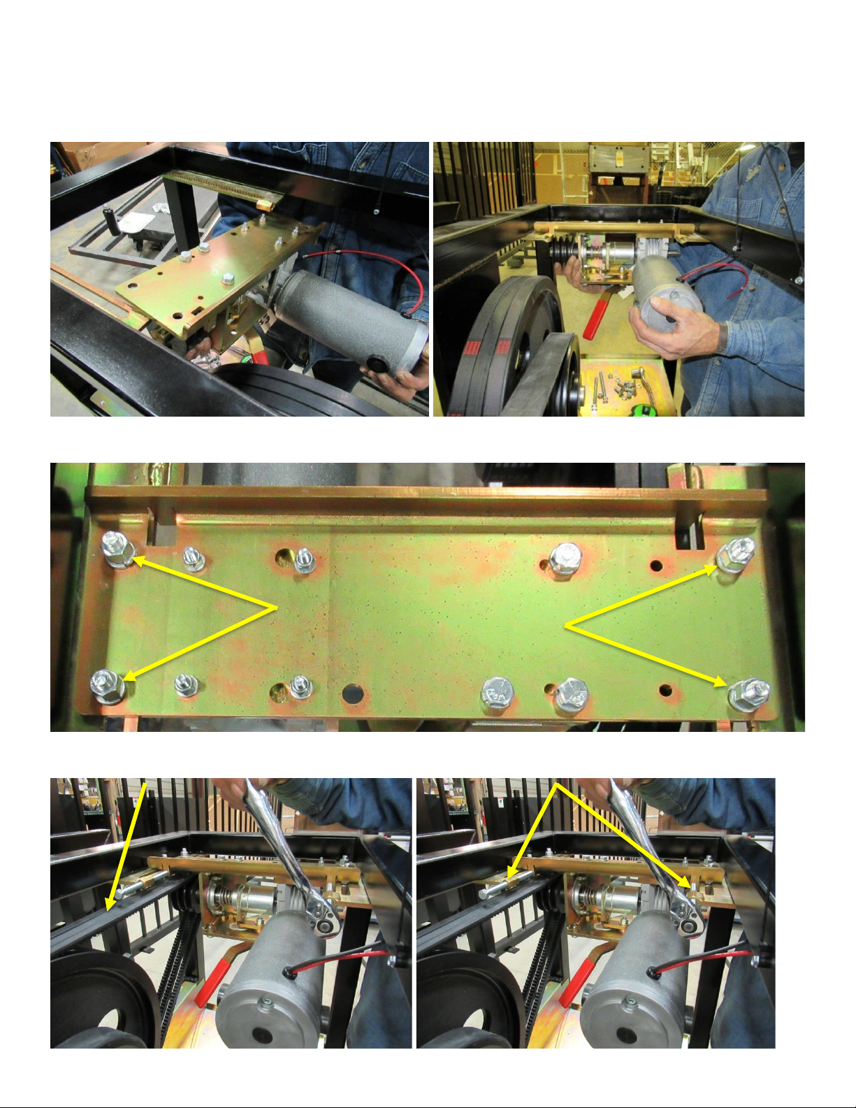
20.) Turn off the AC and DC power switches
21.) Disconnect the motor power wires
22.) Install the Motor Assembly into the operator
23a.) Install four (4) 3/8-16 carriage bolts, lock washers and hex nuts finger tight
23b.) Install three (3) Drive Belts 23c) Install two (2) 3/8-16 Belt Tension bolts
FWI-0001-A –RIGHT ANGLE GEARMOTOR FIELD REPLACEMENT INSTRUCTIONS
24.) Use Belt Tension bolts to adjust the RAD Mounting Plate back to the measurement taken in Step 4 or to the correct
belt tension, (7 ¼” in this example).
25. Take the time to inspect the belts before reinstalling them. Proceed if they are good, by tightening the (3) small
Belts down with ¼” of deflection and the Larger Belt with ½” of deflection by adjusting the Belt Tension bolts.
(This should be sufficient to operate your VPG system.)
26.) Tighten four (4) 3/8-16 hex nuts 27.) Reconnect the motor power wires
28.) Turn the DC and AC power switches on

FWI-0001-A –RIGHT ANGLE GEARMOTOR FIELD REPLACEMENT INSTRUCTIONS
29a.) Ensure the RAD Slide Coupler is locked in the open position
29b.) Jog the motor using the OPEN and CLOSE buttons on the control board to bring the remaining set screws to a more
accessible location for tightening
29c.) Turn the AC and DC power switches off then finish tightening the set screws
30.) Remove the T/M Safety Pin to unlock the gate
31.) Turn the AC and DC power switches on
32.) The operator is now ready to run
33.) Cycle the gate several times to ensure the alignment is correct
34.) Test all entrapment devises for proper operation
35.) Check Maintenance log to verify no preventative maintenance is needed.
36.) Re-Install the top panel
Other AutoGate Gate Opener manuals
 User manual")


Popular Gate Opener manuals by other brands


Merlin
Merlin G740A Instructions for installation & use

Beninca
Beninca DU.35L Operating instructions and spare parts catalogue

cedamatic
cedamatic CD.S20 operating instructions

Cardin Elettronica
Cardin Elettronica TECHNOCITY SL1524 Replacement procedure

Merlin
Merlin Swing A 200 Quick reference guide

Casit
Casit EQ2006 manual