AutoGate VPG2490 Reference manual

1
2490/GENESIS Introduction
MODEL VPG2490
FULL SIZE MANUAL AVAIALBLE TO DOWNLOAD AND PRINT AT WWW.AUTOGATE.COM

2
VPG2490 OPERATOR
TheVPG2490isAutoGate’snewUL325Rev7ListedVercalPivotGateOperator.TheVPG2490em-
ploysa90°,(RightAngleDrive)gearmotor,andanewlydesigned24VDCcontroller(GenesisBoard)and
ulizesanewLimit/PosionSensor(LPS)todetectgateposion.Theframeforthismodelis2”tallerthan
thepreviousmodeltoallowforclearancebetweenthewindbracingandtheendpaneloftheoperatorcab-
inetwhenthegateisfullyopen.Thisallowstheaddionof“OPENEDGE”contactbumpstripstobe
mountedaroundthegatethroatasrequiredbyUL325.InaddiontotheGateThroattheenre
“EntrapmentArea”isrequiredtohave“OPENOBSTRUCTION”proteconperUL325.
VPG2490 BELTS
Thenew90°gearmotorisa½horsepowermotorwithanon-backdrivableright-angledrivegearbox,anda
redesignedsheaveandbeltconfiguraon.Thenewconfiguraonwillprovidebeercontrolofthegatemo-
onandwillpreventthegatefrom"OVERRUNNING"themotor.Therewillbe2driveconfiguraonsused.
Thestandardspeedwillopenorclosethegatein8to10seconds,includingslowdown.Forlargerorextra
heavygatesthespeedwillbereducedslightlytopreventexcessiveweartothedrivemechanismandto
allowforsafercontrolofgatemoon.Thesesystemswillopenorclosein13to15seconds,includingslow-
down.
Adjustmentstothedrivebeltsareacricalpartofthegateoperatorfuncon.Withtheintroduconof
the½horsepowerrightangledrivegearmotor,the'MOTOR'drivebeltshavebeenchangedto"A"secon
belts.Thisnowrequires3beltstohandlethetorque.Anotherreasonforthesizechangefrom"B"to"A"
isitallowsustogetbeergripwithlessbeltwearonthesmallmotordrivesheave.The'GATE'drivebelts
willsllbethe"B"seconbelt.Thiswillconnuetobea"Banded"stylebeltbutwillbethe"Notched"
beltforbeertorqueandgrip.

3
The following are the recommended belt tension adjustments:
Toobtainthemeasurementsplacealongstraightedgeacrossthespanasshownbythedoedlineand
pressdownonthebeltwithasmallforcescaleorfingerpatmidspanbetweenthecontactpointsofthe
beltandsheaves.
Theprimary'MOTOR'driveadjustmentisanaverageofthe3belts.Adjustto.25"defleconwith6to7lbs.
offorce.Also,whenadjusngthe'MOTOR'drivebelttension,makesuretokeepthemotormounngas-
semblysquare,eitherusingatapemeasureorthenotchesinthemounngslides.Whenproperlyaligned
belttensionshouldbethesameinallthreebelts.
The'GATE'drivebelt,onastandardspeedsystem,fromtheintermediatesheavesettothefinaldrive
sheaveisasfollows;defleconof.3"witha5to6lbs.offorceforindividualbeltsor.3"with11to13lbs.of
forceforbandedbelts.
The"GATE"drivebeltonaslowspeedsystem,fromtheintermediatesheavesettothefinaldrivesheave
willhaveadefleconof.3"witha9to11lbs.offorce.
For complete BELT CHANGING instrucons refer to page 14 in this document.
2490 BELTS (cont.)

4
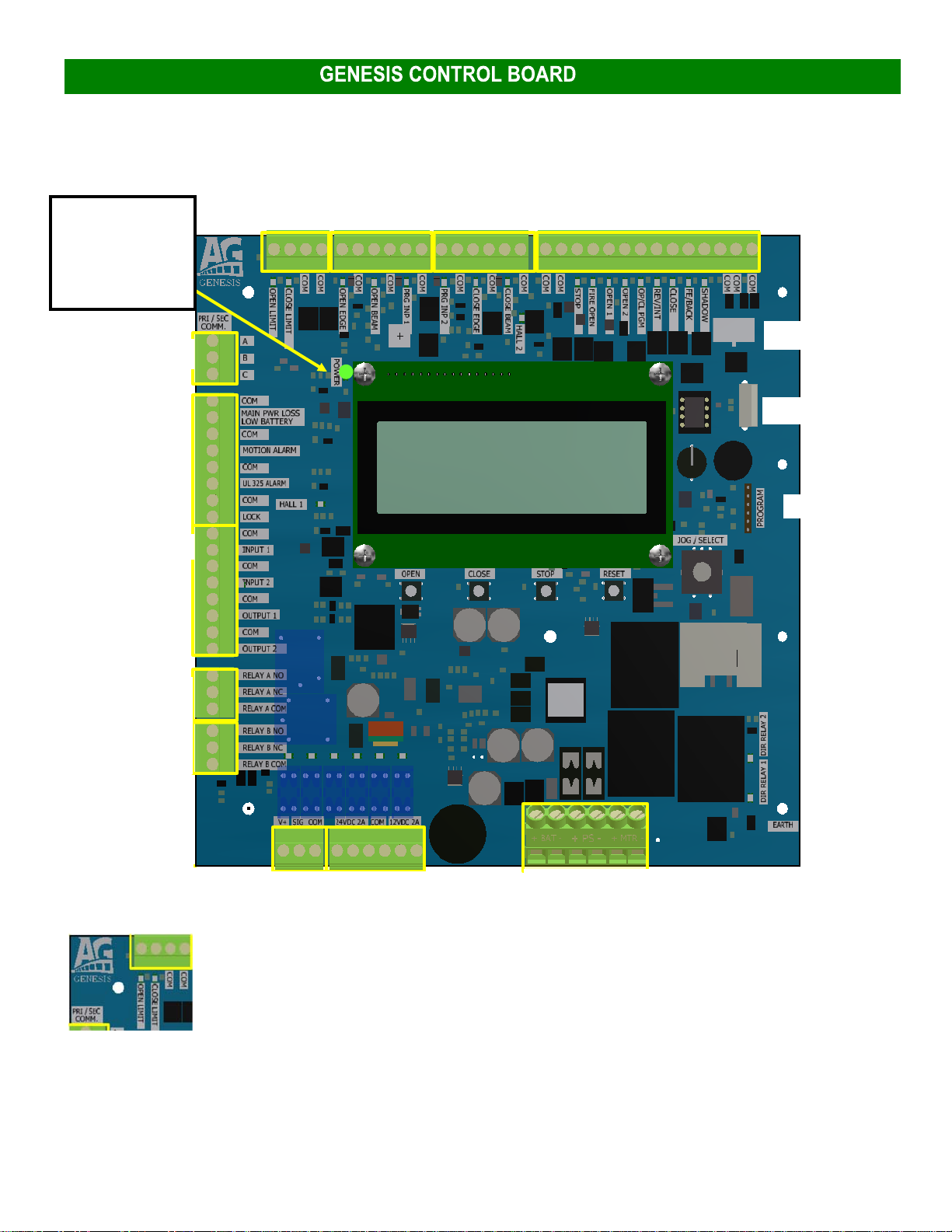
AutoGateisintroducingthe“GENESIS”controlboard.
Genesisisa24VoltDCboardcapableofcontrollingmo-
torsratedupto20Amps.Theboardhasa4line,20
charactersperlinedisplayforinformaonandprogram-
ming.
TheGenesisboardoperatesonDCpower.Ourstandard
systemwillbesuppliedwitha24to28-voltDC/18.8-
amppowersupplyandthePowerSupplysengwillbe
“NORMAL”.Thiswillpowerallfunconsofthegate.
Thereisaninternalbaerycharger/maintainercircuit
ontheGenesisboard.Thesystemwillrequiretwo(2)
12-voltbaerieswiredinseriesorasingle24-volt
baeryconnectedtothebaeryterminalsforback-up
capabilies(HighlyRecommended).Baeriesneedto
bethesamephysicalsize,andthesamecapacityrang.
Thepowersupplyhas(2)voltageinputsengswhichis
controlledbyaswitchonthesideofthecase.Thesengsare115and230.The115-voltsengisfor90
–132voltsACat10Amps.The230-voltsengisfor180-264-voltACat6Amps.
Thereare2morepowerinputsengsontheGenesisboard.Bothsengswillrequire(2)12-volt
baeriesor(1)24-voltbaeryforgateoperaon.OneistheSOLARseng.WhensetforSOLAR,anysolar
arraythatisdesignedfor24-voltchargingcanbedirectlyconnectedtotheGenesisboardinplaceofthepow-
ersupply.Theboardwillsllcontrolthegateasnormal,butthemotorwill
runfromthebaery/baeries.Theon-boardchargingsystemwillnowcharge
thebaeriesfromthesolarpanelswheneverthereisenoughlighttoacvate
thepanels.
NOTE:(2)12-voltsolarpanelswiredinseries,or(1)24-voltpanel,(2
24-voltpanelswiredinparalleltomaximizeoutputcurrent),willproducebe-
tween31VDCand45VDC.Whenthevoltagefallsbelow31volts,thecircuit
willstopchargingandpreventcurrentfrombackfeedingtothepanels.Make
surethatthepropersengischosen.Ifusingthenormalpowersupplyand
theboardissetfor“SOLAR”,thebaerieswillnevergetchargedbecausethe
powersupplyissetto26.5VDC,andthereforewillneverreachthelev-
elrequiredforchargingperthe“SOLAR”program.
Theothernon-standardsengiscalled“CHARGE”.Thiswill
mostlybeusedforbackwardscompabilityonsystemsthatcurrently
useatransformerwhenupgradingtotheGenesis.SincetheGenesis
boardonlyusesDCvoltage,theACtransformerwillnotwork.Byusing
a36-volt4-amppowersupply,the“CHARGE”sengwillworksimilar
tothe“SOLAR”seng.Thepowersupplywilloutput36voltsand
chargethebaeriesandthebaerieswillrunthegate.Butunlikesolar
panels,becausethepowersupplywillalwaysbeon,thechargingcircuit
willalwayswork.Thissetupiseasytoconvertonouroldersystems
usingthetransformerasapowersource.
Genesis Controller

5
GENESIS CONTROLLER (cont.)
TheGenesisboardisprogrammedtomonitortheinputpowerinall3scenarios.Innormaloperaon,
usingtheregularpowersupply,iftheACpowertothesupplyorthepowersupplyitselffails,theREDLEDindi-
catorlightonthedrivewayoperatorendpanelwillflash.Ifthe‘solar’panelsorthe‘charge’supplyfailto
chargethebaeriesformorethan24hours,againtheindicatorLEDwillflash,andawarningscreenwillshow
onthe4-linedisplayindicangthatthereisaproblemwiththesolarpanels,wiring,orthatthereisanissue
withtheACpowertothechargingpowersupplyorthepowersupplyitself.
Ifeitherthe‘NORMAL”orthe“CHARGE”powersupplyhaveanooutputcondion,firsttryturningoff
theACpowerswitch,thenaerafewsecondsturntheACswitchbackon.IftheGenesisdisplayshowspower
supplyvoltageasnormal,thentherewaseitheranovervoltageinputoranoverloadoftheampdrawonthe
output.Thepowersupplieshaveabuilt-inoverloadprotecontopreventdamagetoitselforthecontrol
board.Ifthepowersupplyoverheats,itwillshutdownunlthetemperaturereturnstonormalthenitwillre-
startautomacallyifACpowerispresent.
The12VDCterminalsarefor12-voltaccessories.Justlikethe24-voltterminals,thecommonsinthe
middleoftheblockareusedforthecircuit.Again,bothterminalscombinedhavea2-amploadrang.
Boththe24-voltandthe12-voltterminalsareprotectedbya2-ampfuse.Itishighlyrecommendedthat
thetotalloadoneithersetofterminalsdoesnotexceed1.75Amps.Currentdrawthatequalsthefuserang
couldblowthefuseundernormaluseduetofluctuaonsinequipment.
Thelastsetofterminalsontheboardarehighcurrentloadconnecons.Letorightare,BATT+,BATT-,
24VDC+,24VDC-,MOTOR“A”&“B”.
BATT+=Baeryposivewire
BATT-=Baerynegavewire
24VDC+=Powersupplyposiveinput
24VDC-=Powersupplynegaveinput
MOTOR“A”=WiredtotheREDmotorwire
MOTOR“B”=WiredtotheBLACKmotorwire

6
Note: P1 is NOT USED on the VPG2490 model. The VPG2490 uses a Limit Posion Sensor
(LPS). P1 would only be used if you were to install the GENESIS board in an older operator
with limit switches.
P14– Loop Rack Accessory Wiring harness port: Used with our LR‐3 Loop Rack board
J1‐USB For data connecon (future use)
P6‐Program Plug: Used to update board soware
(cont.)
P4 & P5/Pg. 7‐8
P1/Pg. 6
P11/Pg. 4
P3/Pg. 10
P12/Pg.11
P13/Pg. 11
P8/Pg. 12
P10/Pg. 12 P9/Pg. 11
POWER Indicator. If
the GREEN light is
flashing, there is
power to the board.
J1/Pg. 23
P14/Pg. 23
P1
P6/Pg. 23
P2/Pg. 9

7
TheGENESISboardisoneofthemostadvancedboardsonthemarkettomeetalltherequirementsforen-
trapmentforUL-325.Yourgatewillnotoperatewithoutwiringinthenecessary“reversingprotecon”
equipment.
Theboardhasbeendesignedtomeetjustaboutanyaccessorydeviceandapplicaonyoucanthinkof.
PleasereviewthenextfewpagesfordetailsoneachboardINPUT,OUTPUT,POWERandFUSINGdetails.
Standard INPUTS for OPEN, CLOSE, STOP, Loops, Access Controls, Pushbuttons, etc.
6 “MONITORED” 10K entrapment device INPUTS for OPEN and CLOSE obstruction
Dedicated 1 BEAM and 1 EDGE “OPEN” obstruction
Dedicated 1 BEAM and 1 EDGE “CLOSE” obstruction
Two additional programmable for either OPEN or CLOSE obstruction
Additional Programmable Relays
Additional Programmable INPUTS
Additional Programmable OUTPUTS
24VDC Fused Accessory Power
12VDC Fused Accessory Power
SPECIALNOTE:TheGENESISboardcanberetrofitintoolderoperators.IfaGenesisboardistobeusedinnon-
monitoredentrapmentdevicegatesystem,therequiredOPEN&CLOSEmonitoredinputscanbedeacvated.
Thiswillrequireaspecialpasscodetoallowtheservicingdealer24-houraccesstoprogrammingthatcanbypass
theULRev.6code.Togetthepasscode,aphonecalltoAutoGatewiththegateserialnumberorAG#andthe8
-charactercodedisplayedontheaccessscreen.TheAutoGaterepresentavewillreadbacka5-charactercode
thatwillneedtobeenteredonthedisplay.Again,thiswillallow24-houraccesstothisspecialprogramming
funcon.Aerthat,iftherewouldeverbeareasontoaccessthespecialprogrammingfuncons,anew
passcodewouldbeneeded.
See the following pages for definitions of each terminal on the GENESIS control board.
Genesis Controller (cont.)
P4 & P5
MONITORED DEVICE CONNECTIONS POINTS
GENESIS INPUT & OUTPUT DETAILS

8
MONITORED DEVICE CONNECTIONS POINTS
P4 & P5
Monitored Open Edge
Whenacvated,thegatewillstop,(inlessthan2seconds),andthenreverseandgotoafullclose
securedposion.Gatewillremainclosedunlitreceivesan“INTENDED”INPUT(Keypad/Reader/
PushBuon/FreeExit)ortheboardismanuallyreset(NotfromanEntrapmentinput).
Monitored Open Beam
Whenacvated,thegatewillstop,(inlessthan2seconds),andthenreverseandgotoafullclose
securedposion.Gatewillremainclosedunlitreceivesan“INTENDED”INPUT(Keypad/Reader/
PushBuon/FreeExit)ortheboardismanuallyreset(NotfromanEntrapmentinput).
Monitored Programmable
Input 1 & 2
ChoiceofOpenorClosedireconbyMenu,choiceofEdgeorBeamandthen10Kor2wirebyMenu.
(Refer to PROGRAMMABLE INPUT FUNCTIONAL descripƟons for required acƟon.
Monitored Close Edge
Whenacvatedthefirstme,thegatewillstopinlessthan2seconds,andreversetofullopenand
allowthe‘TimerToClose’tobeacvateduponopenlimit.Uponthesecondacvaonclosing,be-
forereachingthecloselimit,thegatewillagainstop,(inlessthan2seconds),andreversetofull
openandthe‘TimerToClose’willbedeacvated.Thegatewillremainatfullopenunlan
“INTENDED”INPUTisacvated(Keypad/Reader/PushBuon/FreeExit).Theclosecommandwill
closethegateandcleartheholdcommand.An‘Open’commandora“Reverse”command,(notthe
CloseBeaminput)willtriggertheresetofthe‘TimerToClose’acvaon.Also,anyoftheacon
buonsonthecontrolboardcanacvatethegate,(ClosebuonwillclosegateandtheOpen&Stop
buonswillresetthe‘TimerToClose’tobeacve).
Note:Uponthesecondacvaonbeforereachingthecloselimit,whenthegateisinthe“HOLD”
condion,anyinputthatwasbeingmaintainedatthemeofthesecondacvaonshallbeignored
unlthegateisenabledbyadifferentinput!IftheCLOSEEDGEremainsacvated,noinputwillre-
leasethegateforoperaon.
Monitored Close Beam Whenacvated,thegateshallstopinlessthan2seconds,andthenreversetofullopen.The‘Timer
toclose’willbecomeacveonlyaerallinputsareclear.
UL Alarm
Intheeventthegatereceivessequenalobstrucons,theULAlarmwillacvate.Toclear,verifythat
therearenoobstruconsinthemovementpathofthegate.ResetthegatebypressingtheSTOP
buonontheboardorpulsetheSTOPaccessorybuoninput.Ifthegatekeepsstoppingwithalarm
acvaon,checkthebalance,verifythattheOVERCURRENTsengishighenoughtoallownormal
operaonofthegate.Ona2490system,makesuretheLPSisfunconingproperly.

9
Inaddiontotheentrapmentsensorinputsthereareoperaonalinputsforvehicledetecon,communicaonwithanothergate
orsimilardeviceaswellaspushbuonsforcontrolofvariousmodesofoperaon.
Shadow Loop Whileatopenlimit,holdopen,ignoreonceoffoftheopenlimitswitch.(Not com-
mon on VerƟcal Pivot Gate)HoldOpen
FE/Back (Free Exit/
Back Away)
OpensgateasOpen1,butwhensignalisremoved,gateisgivencommandtoclose.
(ClosecommandoverriddenbyanyotheropenorReverse/Interruptcommandor
stopcommand)(PrimarilydesignedtoworkwithFE/BackonBarrierArms)
Startsopeningmovementfromany
posion
Close Loop
Startclosingmovementfromanyposion,Opencommandscanoverride.Ifgateis
closingwhenacvated,gatestopsunlclearandthenconnuestoclose.
Closeinputrespondsonreleaseoftheinputnormally.
Closeinputwillholdthegateopenwhileinputismaintainedwiththegateinthe
openposion.
Wheninconstantpressuremode,closeinputrespondsoninialpress.(Notcom-
mononVercalPivotGate)
Ifheldinupwardmoon,noeffect.
Ifheldindownwardmoon,gate
movementispausedunlreleasedand
connuesdownwardonrelease
Reverse/Interrupt Whenclosing,stopsandre-opens.Ifheld,stayopen
Open / Close PGM
Whenmenuoponnotenabled,Input=open1only.Whenenabled,input=Open
1unlesstheopenlimitisreached,itthenturnstoClose.Ifinputisheldduring
OPEN,gateholdsopen.InputneedstocycleoffbeforeinputcanCLOSEgate.
Ifhelditremainsinitsstate
Open 1 startsopeningmovementfromanyposionstartsopeningfromanyposion
Open 2 startsopeningmovementfromanyposionSameasabove
Fire Open Absoluteopen,unltheboardishardpowerreset,orlocalresetbuonpushedLocksgateopenunlreleased
Stop Stopsgateatanypointandcancelscurrentinputs.Inputswillbeignoredunlstop
isreleased.Astopinputwilldisabletheauto-closemer
Ifheld,nogatemovement,inputsig-
nored.
INPUT NAME FUNCTION AFTER MOMENTARY TRIGGER FUNCTION DURING
CONTINUOUS TRIGGER
P2

10
Warning Light
Four States
OFF: Nofaults
FAST Blink:Lowbaeryvoltage
DOUBLE PULSE Blink:LossofACpower
SLOW Blink:Anyotherfault
priority for the signals are:
1-Lowbaery
2-LossofAC
3-Anyotherfault
Moon Alarm
Acveforfullcycle(ON‐OFFmenuselectable).Programmableforpre-movement
opening(0-5secondsmenuselectable).Programmableforpre-movementclosing(0-
5secondsmenuselectable).
UL325 Alarm AcveforcondionsrelatedtoUL325specificaons
Lock
Programmable/Selectable:
Magnec lock opon-Acvewhenthegateisclosed.
Solenoid Interlock opon-Momentaryacvaontoopentheboltthatmechanically
latchesthegateclosed.
Input 1 OPTIONS: OFF,OPEN,CLOSE,SingleBuon,Reverse,Fire,Shadow,AutoOpen,
HoldOpen,EmergencySecure,AuxiliaryPulse1&2,AuxiliaryHold1&2
Input 2 SameasINPUT1
Output 1 (24VDC)
OPTIONS: OFF,PulseonOpenorCloseLimit,HoldonOpenor&CloseLimit,Pulse
onmotorOpenorClose,HoldonMotorOpenorClose,HoldonULAlarm,Holdon
MotorRun
Output 2 (24VDC) SameasOutput1
P3

11
AUXILIARY RELAYS A & B
OPTIONS:
OFF
PulseonOPENLimit:2-secondRelayAcvaon
PulseonCLOSELimit:2-secondRelayAcvaon
HoldonOPENLimit:LatchesRelayONduringOPENLimit
HoldonCLOSELimit:LatchesRelayONduringCLOSELimit
PulseonMotorOPEN:2-secondPulsewhengatestartstomoveOPEN
PulseonMotorCLOSE:2-secondPulsewhengatestartstoCLOSE
HoldonMotorOPEN:LatchesRelayonwhengateisOPENING
HoldonMotorCLOSE:LatchesRelayONwhengateisCLOSING
P12
P13
AUX Relays A & B: Areprogrammableforoperaonbasedongateaconorposion.Bothrelays
TheGenesisboardhas(2)24VDCoutputsand(2)12VDCoutputstopowerexternaldevices.Eachisfusedat2Amps.
24VDCACCESSORYPower(2)Fusedat2Ampstotal
12VDCACCESSORYPower(2)Fusedat2Ampstotal
P9

12
Primary/SecondarycommunicaonsallowforcommunicaonsbetweengatesforDualGateconfiguraons.
Whenusingtwogatestocoveradrivewayandtheybothneedtocycle
togetheronanopeninput.Connectthetwoboardswitha4-conductor
SHIELDED18ga.wire(3required,1-spare)andsetthefollowingboard
parameters:
P/S:SetforPrimary/Secondarycommunica-
on.Gatesneedtocommunicatewitheach
othertoworkproperly.
YourgateisequippedwithaLIMIT/POSITIONSENSOR.Itwillbeproperlysetwhen
itleavesthefactory.Ifyouneedtoadjustit,refertotheinstruconsbelow.Ifyou
needtoreplace,contactAutoGate.
ADJUSTING THE LIMIT/POSITION SENSOR
1.Inprogrammingmode,SetyourcursortotheGATE(line2)andenter(>Gate).
UsingtheJogknobyoucanslightlyadjusttheOPENorCLOSEposionbyturn-
ingitleorright.
2.Onceyouhavereadjustedyourgateposion,“enter”againtobackoutofthe
GatelineandgouptotheOp:lineordowntotheCl:linetosetyournewnum-
bers.
3.“Enter”(oporCL)andturnthejogknobtothenewnumbersandtestyour
gate.
>Dual Gate Mode:
Off
>Op:4500 Ramp:4000
Gate 1
P8
P10
WARNING! This screen requires a PASSCODE to access.

13
MAINTENANCE
Thebasicelectricalandmechanicalsystemsrequireonlyminimumrounemaintenance.Thefollowingitemsshould
becheckedandservicedperiodicallydependingonamountofuse.Eachitembelowhassupporngillustraonsand/
orinstruconsinthismanual.ContactAutoGateforanyquesonsorissues.Maintenance is important to any gate
system and can affect safety, warranty, quality operaon, and life‐cycle of the system.
ITEM RECOMMENDED MAINTENANCE
GreaseLinkageAssembly(“LUBRIPLATE‘R’LOWTEMP”Grease)10,000cyclesor6months
Greaseallbearings:two(2)OperatorArm,four(4)BullwheelShas10,000cyclesor6months
GreaseChainTensionBoltandLubeChain&lightlycoatsprings
(Useanon-evaporangcableandchainspray)
10,000cyclesor6months
Checkbeltsforwearandghtness.(Seepage44forinstrucons)Every6months
Chargevoltageforbaeriesshouldbe27.5VDCwithbaeriesdisconnected
checkatbaeryinmaintenancemenu.Every6months
Checkbaerywaterlevel,usedislledwateronly(Notrequiredonmainte-
nance-freeorAGMstylebaeries)Every6months
ChecktomakesureallWARNINGsignsareslldisplayedEverymonth
Lubricate(GraphiteOil)alldoorlatch,lockcylindersandmechanismsEvery6months
CleanlensesonPhotoelectricsensors/beamsorReflectorsAsneeded
Cleansnow/iceoffofgate(Balancedcorrectly,gatewilltemporarilytolerate
anaddional10lb.ofwt.)Asneeded
Checkgatebalance(seepage16)Fourmonthsaerinstall,thenannually
CheckandverifyproperoperaonofallExternal monitored entrapmentpro-
tecondevices.
Everymonth
CheckandverifyproperoperaonoftheInternal(TYPEA)entrapmentpro-
tecondevice(LPS)bywalkingtotheendofthegateandstopthegate,it
shouldreverse.
Everymonth

14
ChangingthebeltsonanAutoGateVercalPivotoperatoriseasybyfollowingthestepbystepprocedureoutlinedbelow.Asal-
ways,weareonlyaphonecallawayshouldyouneedassistanceat800-944-4283.
1.Removethe(4) TekScrewsontheTop Panelusinga5/16”nutdriver,removeandsetaside.
2.RemovetheSTIFFENER PLATE(#1)fromthePOISITION SENSOR bracket.Thisallowsaspacetoremovebelts.
3.ReleasetheMOTOR DRIVE BELT(#2)tensionbylooseningthe(4) 3/8” CARRIAGE BOLT nutssecuringtheGEAR MOTOR
bracket (#3)totheSIDE SLIDEplates (#4)witha9/16”wrench.Nowusinga9/16”wrench,backoffthe(2) Gear Motor
FORCING screws(#5)sothatonly1”remainsthroughthecouplingnut.
4.SlidetheGEAR MOTOR assemblytocreateslackinthebelts.
5.Onthecenterofthepulleys.LoosentheFLANGE BEARING bolts(#6)aboutoneturnthatsecuretheshabearingsusinga
15/16”wrench.
6.LoosentheMIDDLE FORCING screw(#7) whichisapplyingtensionontheGATE DRIVE belts(#8) byusinga15/16”wrench.
Thistooneedstobefullyloosenedtoallowenoughroomtoremovethebelts.
7.Removeoldbeltsandinstallnewbeltsloosely.
8.ApplysnugpressuretotheMOTOR DRIVE beltsbyusingthe(2) GEAR MOTOR FORCING screws.Thisshouldalsosnugthe
GATE DRIVE belts.Do not overghten!
9.ThreadtheMIDDLE FORCING screwtofingerght.
10.Re-AssembletheSTIFFNER PLATEtothePOSITION SENSOR bracket.
11.Operatethegateupanddownfor(5)metoseatthebelts.
12.TightentheMIDDLE FORCING screwtoghtentheGATE DRIVE belts.SEE PAGE 3 FOR BELT TENSION INFORMATION
13.TightentheFLANGE BEARING boltsonthemiddlesetofpulleys.
14. TightentheGEAR MOTOR FORCING screwSEE PAGE 3 FOR BELT TENSION INFORMATION
15.Tightenthe(4) CARRIAGE boltstosecuretheGEAR MOTOR brackettotheSIDE SLIDE plates.
16.Operatethegateupanddown5-10mestocheckforproperoperaon.
17.ReplacetheTop Panelusingthe(4)Tekscrews.
1.SffenerPlate
2.MotorDriveBelt
3.GearMotor
4.SideSlide
5.GearMotorForcingScrews
6.FlangeBearingBolts
7.MiddleForcingScrew
8.GateDriveBelts
12
436578

15
SPRING CHANGING INSTRUCTIONS
STEPS:
1. For ease of access, remove the door and end panel
nearest the gate.
2. Disable the photoelectric sensor/beam if equipped.
3. Remove any upper “T” bolts completely and loosen
the slide assembly screws.
4. Loosen the top adjusting nut of the slide assembly.
Thread the nut up to within four (4”) inches of the top of
slide mechanism.
5. You will now raise the gate. (DO NOT release the
disengage lever!) Initiate the gate to open, immediately
move to the gate and help raise it open, once the slide
moves up, hold on the bottom rail of the gate until fully
open. The gate may bounce slightly, there will be a loud
bang but no damage will occur.
6. Turn Off AC/DC Power before gate “times out” and
tries to close. Insert T/M Pin.
7. Using a 1 5/16 wrench, loosen and remove the chain
tension bolt with the damaged spring.
8. Replace damaged spring
9. Replace chain tension bolt. NOTE: Grease fitting
must point down! Tighten bottom nut. NOTE: Chain
MUST remain level and not twisted once tightened.
10. Remove T/M pin and restore AC/DC power.
11. Lowering the gate. Initiate the gate to close and at
the same time, assist the gate down by pulling on the
bottom rail of the gate. The slide will move down and
another loud bang as the gate is lowered.
12. Turn off AC/DC power.
13. Thread the slide nut back down to the slide assem-
bly and tighten.
14. Replace the T-Bolts to their original location and
tighten and tighten the slide assembly screws.
15. Restore AC/DC power and hook photoelectric sen-
sor/beam back up.
16. Cycle gate.
17. Spray all springs with a chain lube to prevent corro-
sion.
18. Grease Chain Tension bolts, Linkage Arm & Bear-
ings
RECOMMENDED: Always check and adjust the balance
after any spring change. Refer to balancing instructions
at www.AutoGate.com or the instructions on Page 16
TOOLS REQUIRED: 5/16” (Nut Driver), 1/2”, 1 1/8”, 1 5/16” Open End Wrenches
WARNING: SPRINGS ARE UNDER A TREMENDOUS LOAD. TAKE EXTREME CAUTION WHEN REMOV-
ING AND REPLACING THEM.

16
BALANCING
TESTING AMPERAGE
1.ConnectAMPmeterinseriesbyremovingthewirenutfromtheREDmotorlead.
2.Cyclegateupanddownrecordingthehighestamperageinthespaceprovidedandadjustinnecessary.high-
estUPandDOWNreadingsshouldnotexceeda1AMPdifference.Forexample:Ifyourhighestreadingis6.5
UPand6>0DOWN,thatwouldbeacceptable.Unacceptablewouldbe3.1UPand8.0)down.
ADJUSTING:
1.LoosenthesetscrewsontheSlideAssemblyaswellasthe11/8”nutsonbothsides(top&boom)ofthe
SlideAssemblyAngle.
2.Onlyadjustthenuts3to4turns(1/4”)atameandcheckyouramperagereadingsaereachadjustment.
NOTE:yourAmpsintheOPENmodeshouldbeapproximately.5(1/2)amphigherthentheCLOSEamperage.
3.IfthegateopenstooslowandisdrawinghighAmps,raisetheSlideAssemblyandrecheck.Ifthegatewill
NOTclose,lowertheSlideAssemblyandre-check.Ifyourgatestallsinetherdirecon,youhaveover-
adjusted.Backoffthelastadjustmentandre-check.
4.Ifthegateisslowstarngtoclosefromtheopenposion,increasethelengthoftheT-Bolt(s).
5.TightenSetScrewsand11/8”nuts.
UP: 10% _____ 55% _____ 85% _____
Down: 10% _____ 55% _____ 85% _____
Table of contents
Other AutoGate Gate Opener manuals
Popular Gate Opener manuals by other brands

CAME
CAME BX708RGS installation manual

Merlin
Merlin G815D Instructions for installation & use

DKS
DKS 6500 Series owner's manual

Avidsen
Avidsen ZENIA250 quick start guide

Motorisation+
Motorisation+ FULL24 Instructions and warnings for installation and use

CENTURION SYSTEMS
CENTURION SYSTEMS VERT-X Mechanical Installation Manual