AUTOHELM ST50 PLUS Specification sheet

Distributed by
Any reference to Raytheon or
RTN in this manual should be
interpreted as Raymarine.
The names Raytheon and RTN
are owned by the
Raytheon Company.

Autohelm’
RADAR
Operation and
Installation

ST50 PLUS RADAR Operation and Installation Handbook
Autohelm and
SeaTalk
are registered Trade Marks of Autohelm Limited
Autoheims
poiicy
of continuous improvement and updating may change product specifications
without prior notice
Copyright Autohelm 1994

ST50 PLUS RADAR Operation and Installation Handbook
Warning
This radar equipment must be installed and operated in accordance
with the instructions contained in this manual. Failure to do so can
result in personal injury and/or navigational inaccuracies. In particular:
1. HIGH VOLTAGE. The radar display unit contains high voltage.
Adjustments require specialized service procedures and tools only
available to qualified service technicians, and there are no user
serviceable parts or adjustments. The operator never should remove
the display unit covers or attempt to service the equipment.
2. ANTENNA. It is recommended that the radar antenna be mounted
above
objects which could interfere with the radar signal such as the
flying bridge, large engine
stacks, and
personnel. This may be difficult
on some vessels and in such a case it is recommended that a radar
mounting pedestal be used. Always turn off the radar system before
servicing the antenna or nearby equipment.
3. ELECTROMAGNETIC ENERGY. The radar antenna transmits
electromagnetic energy. It is important that the radar be turned off
whenever personnel are required to come in range of the antenna to
perform work on the antenna assembly or associated equipment.
When properly installed and operated, the use of this radar will
conform to the requirements of ANSI/IEEE
C95.1-1992
Standard for
Safety Levels with Respect to Human Exposure to Radio Frequency
Electromagnetic Fields, 3 kHz to 300 GHz.
4. NAVIGATION AID. This radar unit is only an aid to navigation. Its
accuracy can be affected by many factors including equipment failure
or defects, environmental conditions, and improper handling or use.
It is the user’s responsibility to exercise common prudence and
navigational judgment. This radar unit should not be relied
upon as a
substitute for such prudence and judgment.

ST50 PLUS RADAR Operation and Installation Handbook ST50 PLUS RADAR Operation and Installation Handbook
Package Contents
1. Display Unit
2. Scanner Unit
3. Inter unit Cable (15m)
4. Power Cable
5.
SeaTalk
Cable
6. Fixing Studs (4
chl)
7. Thumb nuts (4 off)
8. Gasket
9. Template
10. Installation and Operation Handbook
11. Worldwide Service Center book
12. Warranty document

Contents
Contents
Section 1. Introduction...................................................
l-l
1.1 General .................................................................
l-l
1.2 Equipment Features ................................................ 1-2
1.2.1 ST50 Display Unit ........................................... 1-3
1.2.2 Radome Antenna Unit Main Features .................
l-4
1.3 About This
Manual
.................................................. 1-5
1.4 Specifications .........................................................
l-6
1.4.1 General ..........................................................
l-6
1.4.2 Display Unit .................................................... 1-7
1.4.3 Radome Antenna .............................................
1-9
Section 2. Installation ................................................... 2-1
2.1 General ................................................................. 2-1
2.2 Unpacking and Inspection ....................................... 2-l
2.3 Planning the Installation
...........................................
2-3
2.3.1
Mounting the Display Unit
...............................
.24
2.3.1
.l
Console Mounting Instruction.................. .2-7
2.3.2 Radome Antenna
Mounting
............................. .2-8
2.4 Electrical Connection ............................................. 2-16
2.4.1
DC
Power Connection .................................. .2-16
2.4.2 External System Interface ............................. .2-17
2.4.2.1 Connection with External Navaids ......... .2-18
2.4.2.2 Installing the XX Heading Sensor...........
.2-19
2.4.2.3 Interconnection XX Heading Sensor .......2-21
2.4.2.4
Interconnection
(INI-100) ...................... .2-22
2.4.2.5 Seatalk/Compass Interface .................. .2-24
2.4.2.6 Raychart 600Xx Interface .................... .2-24

6ST50 PLUS RADAR Operation and lnstalfation Handbook Radar Glossary
Section
3.
Operation
..................................................... 3-1
3.1 Introduction ........................................................... 3-1
3.2 Radar Map ............................................................. 3-2
3.2.1 Map Operation ............................................... .3-2
3.2.2 Effect of
Ship’s
Movement .............................. .3-3
3.2.3
Navigational
Echoes ....................................... ,3-3
3.2.4 Sea Return ....................................................
.34
3.2.5 Storm and Rain Squall Returns ........................ .3-4
3.2.6 Blind Sector or Shadow Effect ........................
.34
3.2.7 Side Lobes .................................................... .3-5
3.2.8 Rader Interference ......................................... .3-6
3.2.9 False Echoes ................................................. .3-6
3.2.10 Determining Radar Line-of-Sight Range .......... .3-8
3.3 Operating Controls ................................................. .3-9
3.3.1 Layout of the Controls ..................................... 3-9
3.3.2 Functions of the Controls ................................ .3-9
Radar
Glossary
The following is a list of abbreviations and acronyms which may be
used in the text of the manual.
A/D
-
ALM IN
-
ALM OUT
-
CPU
D/A
DEL
DISP
EBL
EXP
FET
FTC
IR
KM
LCD
LL
MH
MN
NM
PCB
PPI
P-S
PW
PWS
RR
SHM
ST-BY
STC
TB
TD
TI
VD
VRM
WPT
X-MIT
-
Analog to Digital Conversion
Alarm In, also known as the “approach” alarm.
For targets approaching a set alarm zone.
Alarm Out, also known as the exit alarm.
For targets exiting or leaving a set alarm zone.
Central Processing Unit
Digital to Analog Conversion
Delete
Display
Electronic Bearing Line
Expansion
Field Effect Transistor
Fast Time Constant, also known as Anti-Clutter Rain
Interference Rejection
Kilometer
Liquid Crystal Display
Latitude/Longitude
Modulator High Voltage
Modulator High Voltage Return
Nautical Mile
Printed Circuit Board
Plan Position Indicator
Parallel to Serial Conversion
Pulse Width (Length)
Pulse Width (Length) Selection
Range Rings (Fixed)
Ship’s Heading Marker
Standby
Sensitivity Time Constant, also known as
Anti-Clutter Sea
Terminal Board
Time Difference
Trigger
Video
Variable Range Marker
Waypoint
Transmit

Section 1. Introduction
1.1 General
Congratulations on selecting the
Autohelm
ST50 LCD Radar for your
radar navigation needs.
Whether you purchased this radar because of its compactness, power
economy, ease of installation, or long term reliability, one thing is
certain; the moment you turn on your ST50 Display you will know you
are seeing a revolutionary new concept in radar technology at work.
You are the proud owner of a radar system unmatched within the
recreational marine industry.
Radar signals are “stored” on an LCD display with chart like clarity and
detail. A single glance at your Display will give
you’s
complete and
accurate 360’ radar picture of other vessels, buoys and landfall
surrounding your vessel.
The
l/8
NM range scale together with the Offset mode makes
navigating tight channels, rivers, or waterways at night a pleasure
instead of a problem.
The Zoom mode gives you a fast 2 times enlargement of the radar
presentation in the zone you have designated. “Timed TX” mode lets
the radar automatically turn its transmitter “on” and “off” for scans of
the area around your vessel to save battery power. Set the target
alarm zone to alert you of any radar contacts that have entered your
zone, including any that might have escaped your notice.
Electronic Bearing Line (EBL), Variable Range Marker
(VRMIand
cursor
allow rapid high accuracy target bearing and range measurements.
When connected to a GPS or Loran Navigator with proper output data
format for full function operation, the radar can display your destination
waypoint
on the screen at its bearing and range from your vessel. The,
Waypoint feature provides steering reference information to the
destination, and can be used to help locate specific buoys or
waypoint
landmarks.
When
intorfard with
the
Rm-hart
fifM7
XX
fnntinnl.
the revolutionary
.
...“..
.a*.-,
,_“__
. . . . . . . ..-
..-
.I
-.--.
-
___.
-.._r.-
,,~
new ability to dsiplay chart information alternately, with the radar
picture, adds simplicity and convenience. The industry standard,
C-
MAP chart cartography, is used to provide you with highly detailed

ST50 PLUS RADAR Operation and
lnstaNation
Handbook Section 1. Introduction
chart information, making navigation both informative and exciting.
The unique Split Screen Mode allows simultaneous viewing of radar
and Seatalk’ Data.
With all of these electronic features and the thoughtful compact and
efficient design of this radar, it soon becomes apparent that human
engineering and operational simplicity have been foremost
considerations in the ST50 product design.
You, the customer, set the high standard for the development of our
products.
We trust that you will enjoy many years of excellent performance,
reliability, and smooth sailing with your new radar system.
To verify your ownership and warranty registration, you should take a
few minutes and fill out your warranty registration card found just
inside the front cover of this manual. It is very important that you take
time to fill this card out. The warranty registration card should be
returned to the factory immediately after your purchase in order to
receive full warranty benefits.
1.2 Equipment Features
The
ST50LCD
Radar system is designed and manufactured to provide
ease of installation and operation combined with excellent reliability.
Some of the many important built-in features of the equipment are
listed below:
1.
2.
3.
4.
5.
6.
7.
Alternate ability to switch between a Radar and a
Raychart
600Xx
screen (option).
Arrow Key for quick information access, anyplace on the display.
Waterproof to U.S.C.G standards, allowing for flexibility of
installation.
Rugged aluminum housing.
The ability to display destination waypoint.
Multi-language operation (English, French, Spanish, German,
Norwegian and Italian.) All six languages are standard within each
system which are selectable via a menu prompt.
Automatic Tuning Feature.
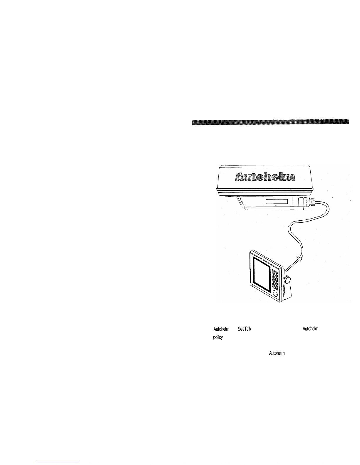
8. Interfaces with
Autohelm
Seatalk instruments, and NAVAIDS,
including Autohelm’s Smart Heading Sensor magnetic compass.
9. Basic radar alignments can be performed via menu prompts.
10. Automatic tune, rain, sea clutter and gain controls.
11. Auto-temperature compensated screen to prevent “darkening” in
sunlight.
1.2.1 ST50 Display Unit
The ST50 display unit uses a monochrome LCD monitor enclosed in
a.compact, aluminum, rugged, waterproof cabinet.
The front panel contains all of the operating controls for the radar
system organized in a combination of controls for precise setting of
the Gain, Tuning, Sea-clutter, and Rain-clutter for clear and detailed
radar presentations and Silicone rubber covered keys to assure fast
and accurate selection of key operating functions. The keys are
logically arranged for the operator’s convenience and are well backlit
for nighttime use.
The display unit is designed to be either tabletop mounted, mounted
on a bulkhead, or in an overhead console. An optional console
mounting kit is available to provide a professional look to custom
installations into consoles or panels.
All system set-up adjustments are made from the display front panel,
negating any requirement to open the display unit cabinet, during the
installation. Screw drivers and adjustment tools are no longer required
for display setups.
Warning
This radar display unit contains HIGH VOLTAGE. Adjustments require
specialized service procedures and tools only available to qualified
service technicians, and there are no user serviceable parts or
adjustments. The operator never should remove the radar unit covers
nor attemot to service this equioment.

ST50 PLUS RADAR Operation and Installation Handbook
The compact design of the display unit is made possible by the use of
custom LSI (Large Scale Integrated circuit) components. An LSI type
of “chip” contains, in one package, the equivalent of up to 30
integrated circuits. Thus compact size, power efficiency, and full
radar navigation features at an economical price are all “standard” in
the ST50 radar system.
1.2.2 Radome Antenna Unit Main Features
The antenna and transceiver are contained within the 18 inch radome
assembly, the radome is made of AES plastic and has a single-flange
mounting. The radome protects the electronic assemblies from the
environment, yet is transparent to the radar’s RF energy, thereby
allowing full performance. A small, flexible interunit cable connects the
Radome Unit to the Display Unit.
The radome cover is secured to the pan base by four clamping bolts
and is provided with a heavyduty rubber
gasket
to completely seal the
unit from the weather and salt spray.
Inside, the radome features a printed-circuitcard array. This technically
innovative antenna provides a narrow 6’ beamwidth for excellent short
;
range resolution and high gain in a very compact antenna package.
The internal X-band transmitter operates at a 2
kW
peak power, with
i
a sensitive micro-integrated circuit
(mic)
front end receiver. j
The construction of the antenna unit is modularized, so repairs, should
they be required, can be made quickly and cost-effectively.
Section 1. Introduction
1.3 About This Manual
This manual contains important information to help you get the best
operation and performance from your new ST50 and its associated
optional equipment. Although the unit is actually pretty simple to
master, please take the necessary time to read through each section.
Section 2 containsveryimportantinformationon the proper installation
of your new ST50 Radar. Although the typical installation might seem
straight forward and simple, we highly recommend that this section be
read thoroughly and the guidelines for installation be closely followed
to obtain trouble-free and efficient operation of your new units.
Section 3 contains a brief discussion of the general principles of radar,
along with the operating instructions for the ST50 Radar which will
guide you through the unit? operating controls and display layouts. To
more easily recognize how to enable the various operations, the
names of the keys that must be pressed to complete the described
operation are enclosed
in
boxes, such as
ml
, or
-1.
In most cases, pictures, showing the correct
displays to obtain the desired entry, are included next to each function.
The best way to learn about your ST50 is to dive right in. You can’t
damage the unit by randomly pressing keys. So don’t be afraid to
experiment. In Menu mode, if at any time the results appear confusing,
just push
themhey
twice in order to return to the Main menu, and
start again.
In the event that your ST50 should ever experience an operational
failure, it is recommended that all repair services be provided by an
authorized service dealer or by the Factory Service Center.

1-6 ST50 PLUS RADAR Operation and
fnstallation
Handbook
1.4 Specifications
1.4.1 General
1)
Maximum range: 16 nautical miles
2) Minimum range: Less than 35 m (25 yds) on the
.125 nm range.
3) Range Scales: Range Number of
Range ring
rings interval
0.125 nm 20.0625 nm
0.25 nm 20.125 nm
0.5 nm 20.25 nm
0.75 nm 30.25 nm
1.0 nm 40.25 nm
1.5 nm 60.25 nm
3 nm 60.5 nm
6 nm 61 nm
12 nm 62 nm
16 nm 44 nm
4) Range discrimination: Less than 35 yds.
5) Range ring accuracy: Better than
f
1.5% of maximum range of
the scale in use, or 22 m, whichever is
the greater.
6) Bearing accuracy: +1 degree.
7) Display device LCD: Diagonal 168 mm (6.6’)
Effective display area 134.4 x 100.8
;n5fl
x
3.9’)
8) Environmental conditions:
Radome: Temperature
-15-C
to +55-C
Humidity Up to 95% at 35-C
Display Units:
Temperature -10-C to +55’C (EXCEPT
LCD)
Temperature O’C to +40-C
(LCD)
Humidity Up to 95% at 35-C
9)
Input power requirements: 10.2
m
16V dc
10) Power Consumption: 30 W
Note: LCD performance will be slightly deteriorated in response
speed and brightness during extreme low temperatures.
Section
1.
Introduction
1.42 Display Unit
1)
2)
3)
4)
5)
6)
7)
Dimensions:
Mounting:
Weight:
LCD:
Width 208 mm (8.2’)
Depth 68 mm (2.7’)
Height 198 mm (7.8’)
without bracket
Table, bulkhead, overhead or flush
mounting
Approx. 1.8 kg (Approx. 4
Ibs)
7’ equivalent display area (6.61’
diagonal)
Contrast: Auto temperature, sensing
compensation
Video
4 levels quantitized.
Display Resolution:
320 x 240 pixels
Bearing synchronizing system: Motor Encoder
8) Tuning:
9) Bearing scale:
10)
Ship’s heading marker:
11)
VRM:
12) EBL:
13) EBL Resolution:
14) Alarm:
15) Off Center
16) Zoom
17) Timed TX
Auto/Manual
360’ scale graduated at intervals of 10’
Electrical
Digital readout on LCD in the range of
0.00 to 16.0 nm, 3 digit
Digital-On-
Screen-Display
Digital readout on LCD in the bearing of
0’ to
360’,
3 digit Digital-On-Screen
Display
1’
Audible alarm and zone mark on PPI
Up to 66% radius (all ranges, except 16
nm range scale)
X2 enlargement any range except
l/8
nm scale.
Rotation Period Select 10, 20 or 30
Scans
Repetition Period Select 3, 5, 10 or 15
Minutes

l-8 ST50 PLUS RADAR Operation and Installation Handbook
18) Features
Other Optional Features:
19)
Control Keys
(All push
bottons)
inputs:
Loran-C/GPS
Seatalk
Cursor, VRM, EBL, Interference Rejection,
Target Expansion, Target Alarms, LAT/
LONG or TD Readouts, Waypoint
t/L,
Off
Center/Zoom, Timed Transmit, Target
trails, Built in Simulator, Hold Mode, Auto
Gain, Auto STC, Auto FTC, Auto Tune
Raychart,
Seatalk
RANGE KEYS
,TUNE
KEYS
RAIN KEYS
SEA KEYS
GAIN KEYS
HOLD KEY
MENU KEY
GUARD KEY
EBL KEY
VRM KEY
CURSOR KEY
CTR/ZOOM KEY
CONT/DIM KEY
STBY/XMIT KEY
UP/DOWN
UP/DOWN
UP/DOWN
UP/DOWN
UP/DOWN
OFF/ON
OFF/ON
OFF/ON
OFF/ON
OFF/ON
OFF/ON
OFF/ON
OFF/ON
OFF/ON
A, v’,
4,
b,
DIRECTION KEYS
NMEA0183, must include GLL, GTD, VTG,
BWC, or RMA and RMB, or RMB and RMC
sentences for full function displays and
capabilities.
Magnetic Sensor NMEA 0183 HDM, HDT,
VHW or HSC, data sentences.
Wind Direction, Wind Velocity, Depth,
SOG/
COG, MTW, Position, Waypoint, Tide, etc.
20) Rear Panel Connectors:
Inter-unit (Ant.1
lo-pin
Power DC input/
4-pin
NMEA
Compass/Seaiaik i-pin
Raychart
B-pin (option)
Section 1. Introduction
1.4.3 Radome Antenna
1)
2)
3)
4)
5)
6)
7)
8)
9)
Dimensions:
Weight:
Polarization:
Beam width:
Sidelobes:
Rotation:
Diameter of radome 450 mm (17.7’)
Height
227
mm (8.9’)
Base Dimensions Front to end
270
mm
(10.6”)
Width
200
mm (7.9’)
Approx.
5.5
kg (12.1 Ibs)
Horizontal
Horizontal 6’ nominal
Vertical
25’ nominal
-21
dB
or greater (within +lO’)
Approx. 24 RPM
Drive motor input voltage:
Transmitter frequency:
Peak power output:
10) Transmitter device:
11) Pulse length/Pulse
repetition frequency:
12) Modulator:
13) Duplexer:
14) Mixer:
15) IF amplifier:
16) Noise figure:
17) Characteristic:
+12
VDC
9445k30
MHz
2.0
kW
Magnetron
(RMC-21
O.O8ps/2250
Hz
(0.125, 0.25, 0.5, 0.075
nm)
0.3
p/l200
Hztl,
1.5nm)
0.8
p/600
Hz
(3,6,
12, 16 nm)
Solidstate modulator driving magnetron
T-junction with diode limiter
MIC front end
Center frequency
60
MHz
Bandwidth
7
MHz
Less than 10
dB
Linear

Section 2. Instal/ation
Section 2. Installation
2.1 General
Congratulations on selecting the
Autohelm
ST50 LCD radar to meet
all of your radar navigation requirements.
Although your ST50 radar is designed to the highest levels of quality
and performance, it can only attain those standards when a proper
installation of the equipment has been achieved.
This section provides practical guidelines to assist in the planning and
installation of the ST50 aboard your vessel.
2.2 Unpacking and Inspection
Use care when unpacking the ST50 radar from the shipping carton to
prevent damage to the contents. It is also good practice to save the
carton and the interior packing material until the radar has been
satisfactorily installed on the vessel. The original packing material
should be used in the unlikely event that it is necessary to return the
unit for service.

ST50 PLUS RADAR Operation and Installation Handbook
2.3 Planning the Installation
The layout for installing the ST50 radar should be planned to give the
best operation and service aboard your particular vessel. In general,
the Radome Unit should be mounted as high as possible above the
waterline. The Display Unit should be installed in a convenient viewing
position near the helm. Keep in mind the optimum viewing angle when
installing the display. You may want to apply power in advance of
installing the unit so that you can determine a satisfactory viewing
angle prior to installation.
Note: In order
to maximize the operation of your radar system,
it is recommended that the radar antenna be mounted above
objectswhich would interfere with theradarsignal. Installation
ofthe radar antenna abovesuch obstacles as theflying bridge,
largeenginestacksandoutoftherangeofpersonnelwillinsure
maximum benefit from your radar system.
A 15 meter (50’) length of Vinyl-covered, shielded, 8 conductor cable
is furnished with connect plug and terminal connections for
interconnecting the two main units (Scanner and Display).
This length of cable should be sufficient to complete the cable run
required on most small vessels. It is recommended that the maximum
length of cable between the Scanner Unit and the Display Unit not
exceed 20 meters (60’).
A General System diagram for the ST50 is shown below.
Section 2. Installation
2-3
;;
7.
.>===--r==-----
I
----_-
u
:: hlagne!ic’
:!
sensor
‘:
‘-2
.eY
Stable
Heading SanSOr
Fig. 2-1 General System Diagram
2.3.1 Mounting the Display Unit
When planning the installation for your ST50 LCD Display Unit, the
following conditions should be considered to insure dependable and
trouble free operation.
1) The mounting location should be easily accessible to allow
operation of the front panel controls.
2) There should be adequate ventilation.
31
There should be sufficient space behind the display to allow cable
connections to the rear
panei
connectors.
4) The Display Unit should be located near a DC power source.

ST50 PLUS RADAR Operation and Installation Handbook
5) The selected location should be far enough away from devices
that may cause interference, such as motors and generators.
6) Generally speaking, the display should be located in a protected
area away from prolonged direct exposure to rain and salt spray.
It is good practice to protect your valuable electronic equipment
as much as possible.
The Display Unit can be conveniently mounted on a chart table,
bulkhead, overhead or console mounted in a desired locatin. (Refer to
Figure 2-2 for typical mounting methods).
Bulkhead Mounted
Overhead
Mounted
Table Top
Mounted
Fig. 2-2 Typical Mounting Methods
Section 2. Installation
2-5
DISPLAY WEIGHT: 1.
8Ke
(4.
131b)
_DIMENSiONS
SHOWN IN MILLIMETERS
AN0 INCHES
-_.__._-.
Fig. 2-3 Display Mounting Dimensions

2-6
ST50 PLUS RADAR Operation and Installation Handbook
2.3.1.1 Console Mounting Instructions
The procedure below can be used to console mount the ST50 Display.
~
Refer to the console mounting figure to see how the various hardware
items are arranged during assembly. I
/
Fig. 2-4 Console Mounting the Display
1. Select the location for the unit. A clear, flat area of at least 8” wide
by 9” high having at least 6” of clearance depth behind the panel
is required.
Caution
Make sure there are no hidden electrical wires or other items
behind the desired location before proceeding. Checkthatfree
------ C-r
-a..-a:..~
. .
..A
n.lh,:n,,
ic
~\,a;lsJk(P
dG;liC:JD
I”, ,,wur,n,,g Pll” ua”,,,,6 I*
“.“..“I.“.
Section 2.
lnstaflation
2-7
2. Unpack the template mounting kit and also confirm that all
hardware is present.
3.
Using the instruction template supplied with the kit, trace out the
appropriate screw hole locations for flush mounting including the
display unit opening.
4.
Drill a
l/2’
pilot hole in each opposing corners of the cut-out area.
5.
Using an appropriate saw, cut the outside edge of the
cut-out
line.
6.
Remove the yoke knobs, from the display cabinet. Check that the
unit will fit into the cut-out area.
7. Complete the installation of the DC power cabling, antenna cable,
data input, ground, and any other accessory cables, into the
console.
8.
Slide the unit into the cutout of the panel. A suitable sealant may
be used between the trim ring and console to prevent moisture
entry.
9. Use the hardware supplied in the kit to secure the unit to the
console. Tighten the hardware as necessary. Connect all cables
to the unit rear panel.
2.3.2 Radome Antenna Mounting
Selecting the best location for the Scanner Unit requires careful
consideration. On many small vessels, the unit can be installed on a
mast platform, on an arch, or on bridge structure. Since radar
basically operates at line-of-sight, the unit should be mounted as high
as possible on the vessel to obtain the best long range performance.
The scanning beam should not be obstructed by surrounding large
objects. Try to locate the radome unit where other large structures or
equipment such as searchlights, horns, or masts are not in the same
horizontal plane, otherwise, blind areas and false targets can appear
on the radar screen.
Installation near the top of exhaust stacks must be avoided as damage
to the radome could result excessive heat and the corrosive effects
nf Ct3f-k cl2crx
“I
.s~U”I.
D...-.....

2-8
ST50 PLUS RADAR Operation and Installation Handbook
Fig. 2-5 Outline Drawing of Radome Antenna Unit
OPTIONAL MAST MOUNT:
POCYESTEA GLOSS WHITE FINISH
DIE CAST ALUMINUM CONSTRUCTION
STAINLESS HARDWARE
WEIGHT: 4.5 tbs.
FITS MASTS FROM 2’1:‘ OIA AF;D UP
Fig.2-6UniversalMastMount(M88390)
Section 2. Installation
Warning
It is recommended that the radar antenna be mounted above
objects which could interfere with the radar signal such as the
flying bridge, large engine stacks, and personnel. This may be
difficult on some vesselsand in such a case it is recommended
that a radar mounting pedestal be used. Always turn off the
radarsystembeforeservicingtheantennaornearbyequipment.
For sailboat installations, Raytheon offers a universal mast mount kit
ProductCodeM88390). Thisoptionalmount fitsmastswithdiameters
from 2
l/4’
and larger. When using the mast mount kit, appropriate
hardware should be used for the style and structure of the mast aboard
the vessel.
If there is any doubt concerning the appropriate type of hardware,
consult with your boat dealer or representative ,for their
recommendations.
Depending on the type of sailboat, a radar antenna guard should be
installed if the sails tend to contact the antenna platform. Without a
proper radar guard, serious damage could result to the mounting
platform and the radar antenna.
Fig. 2-7 Typical Installation for Sailboat Showing In-line Connection
at Mast Base

ST50 PLUS RADAR Operation and Installation Handbook
Using the outline drawing of the Scanner base or template in the back
of the manual as a guide, prepare the mounting surface with the four
mounting holes as required. Install the Scanner and secure it to the
mounting surface. The correct mounting hardware is stainless steel
hexhead bolts
5/16’,
1
l/4’
long with 18 UNC thread. A flat and lock
washers should be used. The Scanner should be parallel to the ship’s
waterline and oriented so the cable inlet is pointed AFT.
ANTENNA. It is recommended that the radar antenna be mounted
above objects which could interfere with the radar signal such as the
flying bridge, large engine stacks, and personnel. This may be difficult
on some vessels and in such a case it is recommended that a radar
mounting pedestal be used. Always turn off the radar system before
servicing the antenna or nearby equipment.
Caution:
When mounting the scanner unit, please observe a minimum
mounting surface thickness of
.25
inches. If the thickness of
the mounting base is too thin, the modulator PCB could
potentially be damaged (Fig. 2-8). The mounting base should
beatleast0.25inchesthick.Useadditionalwashersifnecessary
to meet this requirement.
P.S./Modulator PC0
%
2
linch Mar
Thickness Mounling bx.o(min. thickness 0.25 inch)
Plain washer
Cock washor
S~aioloss stcci bob
5116.10UNC
,
I
I
I
,
I
/
,
I
I
!
I
I
I
I
/
I
I
I
Section 2. Installation
Some vessel’s however, may adopt a HIGHER BOW angle when the
vessel is at it’s cruising speed that substantially alters and raises the
radar’s main radiation plane. In this case nearby target detection might
be poor. It may be helpful to lower the radar beam towards the parallel
by shimming the radar pedestal to tilt the beam angle slightly
downward with respect to the waterline.
The figure shows one approach, that of using an angled wood block
between the pedestal mounting feet and the mast or platform surface
to obtain the desired tilt angle. The shims may also be made from
aluminum plate wedges or simple flat washers.
Setting the Radiation
Plane
In the standard antenna
installation the scanner/
pedestal unit is mounted so
the array will rotate parallel to
the waterline. The beam of
the radar is approximately
25”
wide in the vertical direction
so target detection during the
vessel’s pitching and rolling
will be generally good.
,OEAL
RADIATION PlANE
Fig. 2-8

2-
12
ST50 PLUS RADAR Operation and installation Handbook
I
I
Step 1. Loosen the 4 clamping bolls
securing the radome and remove the
radome cover. -The clamping bolts are
captive and should remain in the lower
flange assembly.
Step 2. Remove watertight gland and
grommet where the interconnect cable
enters the radome base.
Remove shield jacket retaining plate.
Step 3. Slide gland nut and the rubber
grommet onto the cable and insert the
connecting cable into the radome base.
Secure the watertight gland.
Step 4. Connect the cable leads to
terminal board
Jl,
using clamping tool
supplied. Ground the shield with the lug
to cable clamp bolt provided. Dress the
wire harness with cable clamps or
tie-
raps as necessary for neatness.
)
Section 2. installation
The cable entrance is provided at the rear of the radome unit. If the unit
is mounted on a hollow mast, the cable may be run inside the mast and
then fed through the radar’s cable entrance.
Before wiring the scanner unit, confirm that the interunit cable is not
connected and power is not applied to the display unit. Connect the
cable leads onto terminal strip JI, using clamping tool as shown below.
Tie shield jacket by retaining plate.
I
A
AlI----
-----
T
Coax. 50 ohms
ELK
-R
.
-----
/
WHT
---.
;
’
YEL
I
0
I
I
I @
T RED
I
I
I
-
SHIELDED WIRE
LARGE WIRE
SMALL WIRE
I
-----J
Fig. 2-10 Wiring Diagram for ST50 Radome Antenna Unit
DC-R
Tl/GS
TUNVIPW
TUNIISHM
+12V/BP
-0V
HV
Fig. 2-9 Connecting Procedure for Radome Antenna Unit

ST50 PLUS RADAR Operation and Installation Handbook
_-------------------_
DISPLAY UNIT
;
I
HV
-SV
E
VD
E
E
TUGS
TUNVIPW
TUNI/SHM
+lZV/BP
+DC
-DC
+NMEA
-NMEA
,______--_--________------ ------I
I
, ANTENNA UNIT
I
I
11
I
1
#
I
I
T ELK
I
8
I
I
01
E
I
I
I
t
@
2
VD-R
8
I
1
COAX. 4
8w
03
VD
,
I
I
I
I
I
I
a
4 DC-R
iI
1
I
I
I
~-~~-~~~~_-~~~~~_-~~--_----J
+TO SHIP’S POWER
I
I
5: LARGE WIRE
------------------J
Fig. 2-11 Radar Interconnection Diagram
Section 2. Installation
2-15
2.4 Electrical Connections
2.4.1 DC Power Connection
The ST50 is intended for use on DC ships power systems and can
operate as long as that DC supply system is maintained from 10.2 to
16 Vdc. The DC system can be “negative” grounded or have both
positive and negative supply lines “floating” above ground. This radar
is not intended for use on “positive” ground vessels.
A 2 m
.I6
ft.) power cable assembly is furnished for connecting the
ship’s DC power into the radar. Longer power cable runs may require
that larger wire sizes be used to minimize anyvoltagedrop in the cable.
In order to properly determine the supply cable wiring size to use if the
power cable must be extended, a graph is supplied in TABLE 2-l for
recommending an appropriate cable diameter. Begin by estimating
the length of cable you will require between the ship’s main power
source and the radar. Select the wire size indicated by the distance
and input voltage.
12VOLTS
-
LLPIJT
VOLTAGE
AWG
WIRE SIZE
POWER CABLE LENGTH
Table 2-1 Power Cable Size Versus Length
Table 2-1 is a recommended guide for selecting power cable wire
sizes based on the length of the cable to the ships’ power connection
point.
The connections should be made at a power distribution panel,
isolation switch, or may
be
made (but not preferred) to the battery.
Check that all connections are clean. The RED wire must be connected
to !+I positive battery terminal and the BLACK wire to
(-1
negative battery terminal. The shielded wire should be connected
to the ships RF ground.
Other manuals for ST50 PLUS
3
Table of contents
Popular Radar manuals by other brands

Endress+Hauser
Endress+Hauser Levelflex FMP55 Brief operating instructions

ABB
ABB LWT300 series user guide

Uniden
Uniden R9 quick start guide

Kustom Signals
Kustom Signals Eagle 3 North Carolina Quick reference guide

Sports Radar
Sports Radar SR3600 instruction manual

Raymarine
Raymarine R11XX Operation manual