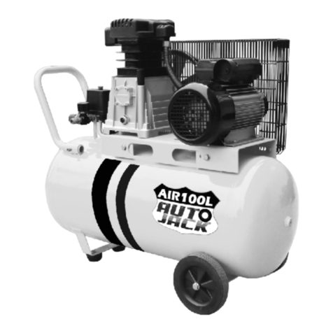
Autojack AIR24L User manual

24 Litre Direct Drive Air Compressor
AIR24L
ORIGINAL INSTRUCTIONS
SAFETY AND OPERATING MANUAL
AIR24L

General Power Tool Safety Warnings… ........................................ 01
Symbols & Cable Rating Chart........................................................05
Machine Details and Product features… ....................................... 06
Assembly… ....................................................................................09
Operation ..................................................................................... 10
Maintenance and Service............................................................. 11
Autojack guarantee.......................................................................13
Declaration of conformity… ......................................................... 15
Parts list… .................................................................................... 16
Parts Diagram… ............................................................................ 18
TABLE OF CONTENTS
Welcome to Autojack!
Dear customer, Congratulations on your purchase. Before using the
Product for the first time, please be sure to read these instructions for use.
They provide you with all information necessary for using the product safely and to
ensure its long service life.
Closely observe all safety information in these instructions!
AIR24L

GENERAL POWER TOOL SAFETY WARNINGS
WARNING Read all safety warnings and
all instructions. Failure to follow the warnings
and instructions may result in electric shock, fire
and/or serious injury.
Save all warnings and instructions for
future reference. The term "power tool" in
the warnings refers to your electric (corded)
power tool or battery-operated (cordless) power
tool.
1. Work area safety
a) Keep work area clean and well lit. Cluttered
or dark areas invite accidents.
b) Do not operate power tools in explosive
atmospheres, such as in the presence of
flammable liquids, gases or dust. Power tools
create sparks which may ignite the dust or
fumes.
c) Keep children and bystanders away while
operating a power tool. Distractions can cause
you to lose control.
2. Electrical safety
a) Power tool plugs must match the outlet.
Never modify the plug in any way. Do not use
any adapter plugs with grounded power tools.
Unmodified plugs and matching outlets will
reduce risk of electric shock.
b) Avoid body contact with grounded surfaces,
such as pipes, radiators, ranges and
refrigerators. There is an increased risk of
electric shock if your body is grounded.
c) Do not expose power tools to rain or wet
conditions. Water entering a power tool will
increase the risk of electric shock.
d) Do not abuse the cord. Never use the cord for
carrying, pulling or unplugging the power tool.
Keep cord away from heat, oil, sharp edges or
moving parts. Damaged or entangled cords
increase the risk of electric shock.
e) When operating a power tool outdoors, use an
extension cord suitable for outdoor use. Use of a
cord suitable for outdoor use reduces the risk of
electric shock.
f) If operating a power tool in a damp location is
unavoidable, use a residual current device (RCD)
protected supply. Use of an RCD reduces the risk
of electric shock.
3. Personal safety
a) Stay alert, watch what you are doing and use
common sense when operating a power tool. Do
not use a power tool while you are tired or under
the influence of drugs, alcohol or medication. A
moment of inattention while operating power
tools may result in serious personal injury.
b) Use personal protective equipment. Always
wear eye protection. Protective equipment such
as dust mask, non-skid safety shoes, hard hat, or
hearing protection used for appropriate conditions
will reduce personal injuries.
c) Prevent unintentional starting. Ensure the
switch is in the off position before connecting to
power source and/or battery pack, picking up or
carrying the tool. Carrying power tools with your
finger on the switch or energising power tools that
have the switch on invites accidents.
d) Remove any adjusting key or wrench before
turning the power tool on. A wrench or a key left
attached to a rotating part of the power tool may
result in personal injury.
AIR24L
01

GENERAL POWER TOOL SAFETY WARNINGS
e) Do not overreach. Keep proper footing and
balance at all times. This enables better control
of the power tool in unexpected situations.
f) Dress properly. Do not wear loose clothing or
jewellery. Keep your hair, clothing and gloves
away from moving parts. Loose clothes,
jewellery or long hair can be caught in moving
parts.
g) If devices are provided for the connection of
dust extraction and collection facilities, ensure
these are connected and properly used. Use of
dust collection can reduce dust-related hazards.
4. Power tool use and care
a) Do not force the power tool. Use the correct
power tool for your application. The correct
power tool will do the job better and safer at the
rate for which it was designed.
b) Do not use the power tool if the switch does
not turn it on and off. Any power tool that
cannot be controlled with the switch is
dangerous and must be repaired.
c) Disconnect the plug from the power source
and/or the battery pack from the power tool
before making any adjustments, changing
accessories, or storing power tools. Such
preventive safety measures reduce the risk of
starting the power tool accidentally.
d) Store idle power tools out of the reach of
children and do not allow persons unfamiliar
with the power tool or these instructions to
operate the power tool. Power tools are
dangerous in the hands of untrained users.
e) Maintain power tools. Check for misalignment
or binding of moving parts, breakage of parts and
any other condition that may affect the power
tool’s operation. If damaged, have the power tool
repaired before use. Many accidents are caused
by poorly maintained power tools.
f) Keep cutting tools sharp and clean. Properly
maintained cutting tools with sharp cutting edges
are less likely to bind and are easier
g) Use the power tool, accessories and tool bits
etc. in accordance with these instructions, taking
into account the working conditions and the work
to be performed. Use of the power tool for
operations different from those intended could
result in a hazardous situation.
5. Service
a) Have your power tool serviced by a qualified
repair person using only identical replacement
parts. This will ensure that the safety of the power
tool is maintained.
b) If the replacement of the supply cord is
necessary, this has to be done by the
manufacturer or its agent in order to avoid a
safety hazard.
AIR24L
02

GENERAL POWER TOOL SAFETY WARNINGS
7Additional Safety Instructions for Paint
Spraying
7.1
Do not use paints or solvents whose flash
points are below 55°C as there is a risk of
explosion.
7.2
Never heat up paints or solvents this can
lead to fires or explosions.
7.3
If using hazardous liquids, wear protective
face guards and adhere to all safety
information for the liquids provided by the
manufacturer.
7.4
Do not smoke while operating and/or in the
work area. Paint vapours and other small
particulates are highly combustible and can
explode.
7.5
Evaluate the situation and wear suitable
clothing and masks if the situation calls for it.
7.6
Never set up or operate the machine while
near to or in the vicinity of a fire place, open
lights, sparking machines or any naked flame.
7.7
keep food and drink away from work area
paint vapours are damaging to your health.
7.8
Use in a well ventilated area.
7.9
Ensure that the work area is at least .
7.10
Do not use materials such as white spirits,
Butyl Alcohol and methylene chloride with the
PVC hose. These materials will destroy the hose
damaging the product and creating an unsafe
work environment.
AIR24L
03
6Additional Safety Instructions for
compressed air and blasting guns
6.1
During operation Compressor pump and
lines can become extremely hot. Touching
these parts is dangerous and will burn you.
6.2
Air which is compressed must be kept free
of any impurities which could cause fires or
explosions in the compressor pump.
6.3
Always secure the hose coupling as you
release it. This prevents injury caused by a
rebounding hose.
6.4
Wear Safety goggles when using the
blowout pistol. Eyes are extremely sensitive
and easily injured by small and large foreign
bodies, which are disturbed when using the
pistol.
6.5
Do not use or point the Blowout pistol on
or at others.
6.6
Do not clean clothes or use on yourself
this can cause injury.

GENERAL POWER TOOL SAFETY WARNINGS
8Additional Safety Instructions for
operating pressure vessels
8.1
Vessel must be kept in good working
order, any repair or maintenance work
necessary must be carried out immediately.
8.2
Supervisory authority may enforce
essential control measures in individual cases.
8.3
DO NOT US A DEFECIENT OR FAULTY
PRESSURE VESSEL. This can seriously
endanger workers or third parties.
8.4
Always check your pressure vessel for
signs or rust and damage before each use. Do
not use if found to be damaged.
9. Using an Extension Cable.
9.1 If an extension cable is required, use an
approved triple core extension cable suitable
for the power input of the tool.
9.2 Grounded tools always require a three wire
extension cable.
9.3 As the distance from the supply outlet
increases you must use a heavier gauge
extension cable. Using extension cables with
inadequately sized wire causes a serious dropin
voltage, resulting in loss of power and possible
tool damage.
9.4 The smaller the gauge number of the wire
the greater the capacity of the cord.
9.5 When using a cable reel, always unwind the
cable completely.
AIR24L
04

Caution! Wear a dust mask.
Caution! Risk of Injury! Do
not reach into the running
saw blade.
Caution! Wear ear defenders. The
impact of noise can cause
damage to hearing.
Caution! Wear safety goggles.
Danger! – Read the operating
instructions to reduce the risk of
injury.
Amperes
7.5M
15M
25M
30M
45M
60M
0 – 2.0
6
6
6
6
6
6
2.1 – 3.4
6
6
6
6
6
6
3.5 - 5.0
6
6
6
6
10
15
5.1 – 7.1
10
10
10
10
15
15
7.1 – 12.0
15
15
15
15
20
20
12.1 – 20.0
20
20
20
20
25
-
SYMBOLS AND POWER RATING CHART
AIR24L
05

13. Oil filler opening
14.
Oil sealing plug
15.
Oil drainage screw / Oil level window
16.
Cylinder
17.
Discharge line
18.
Alex screw
19.
Nut
20.
Washer
21.
Screw
22.
Nut
23. Washer
1. Intake air filter
2.
Pressure tank
3.
Wheel
4.
Foot
5.
Quick-lock coupling
6.
Pressure gauge
7.
Pressure regulator
8.
ON/OFF Switch
9.
Transport handle
10.
Safety valve
11.
Condensation drainage screw
12. Non-return valve
MACHINE DETAILS AND PRODUCT FEATURES
AIR24L
06
Product Features
Quick coupling valve
24Litre tank
Intended Use
Designed to generate compressed air
Using equipment in ways other than its
intended use the user and not the
manufacture will be liable for any damage or
injuries caused.
Also note that this equipment is not designed
for commercial or industrial use. Warranty will
be voided if used for these purposes.
Machine Details
Specifications:
Mains Voltage - 230V / 50Hz
Output - 1100W/1.5HP
Motor speed – 2850rpm
Capacity – 24Litre
Operating pressure – approx. 8 bar
Theoretical intake –approx. 165l/min
Sound power level – 97 dB (A)
Gross Weight – 25Kg
Package Contents:
Air Compressor
Wheels and axle set
Rubber stopper
Air filter
Oil breather plug
A bottle of oil

MACHINE DETAILS AND PRODUCT FEATURES
AIR24L
07

MACHINE DETAILS AND PRODUCT FEATURES
AIR24L
08

1. Before starting to assemble the
equipment
1.1 Check equipment for damage which may
have occurred in transit. Report this
immediately to the carrier used for delivery.
1.2 Assemble and install near the area
intended to be used.
1.3 Avoid long electric wires and air lines.
1.4 Avoid Installing in a damp or wet
environment.
1.5 Check the air is dry and dust free.
1.6 You cannot use the compressor in an area
where work is conducted with sprayed
water.
1.7 This compressor can only be used in
rooms with good ventilation and
temperature of +0 to +40°C.
1.8 Ensure there is no dust, acid, vapors,
explosive gasses or inflammable gases in the
room.
2. Product assembly
2.1
Fitting wheels
Fit the supplied wheels as shown in Fig.5.
2.2
Fitting the wheels
Fit the supplied supporting feet(4) as shown in
Fig.6.
2.3
Replacing the oil sealing plug
Remove the transportation cover from the oil
filler opening with a screwdriver and insert the
supplied oil sealing plug (14) into the oil filler
opening(Fig. 7).
2.4
Fitting the air filter
Use a screwdriver to remove the
transportation cover from the air filter
connection.
Screw in the supplied air filter (Fig. 8).
Assembly
AIR24L
09

Assembly/Operation
Operation
The pressure in the tank is controlled by the
action of the pressure switch located under the
pressure switch cover.
When the set maximum pressure is reached
the pressure switch activates and the motor is
turned off. The pressure will decrease as the
air is used until the set minimum is reached
after which the pressure switch turns the motor
to on again.
The operator of the compressor should be well
aware that during use of the compressor the
motor will cycle (start and stop) under the
influence of the rising or falling pressure in the
tank and the motor will start without any
warning.
The maximum and minimum pressures are
factory set and should not be altered.
You can utilise either the direct outlet and/or
the regulated outlet. The pressure of the
regulated outlet can be changed by turning the
control knob. Rotate the knob clockwise to
increase pressure and anti-clockwise to
decrease.
Adjusting the pressure
To switch on the compressor, pull out the knob
(8).To switch off the compressor, press the
knob (8) back in. (Figure 2)
Setting the pressure switch
The pressure switch is set at the factory.
Switch-ON pressure 6 bar
Switch-OFF pressure 8 bar
AIR24L
10
3. Initial start up
-
Ensure the unit is stable in a well-ventilated
dry position.
-
Ensure that drain the valve is closed and
air outlets are closed.
Connect the power lead to the mains.
-
Start the compressor by pulling on the red
knob.
-
Check for air leaks.
Warning: Use the red knob to turn the unit
on and off, not the mains switch. Turning the
unit on and off from the mains only will result
in damage to the motor.
3.1 Power supply
●Long supply cables, extensions, cable
reels etc. cause a drop in voltage and can
impede motor start-up.
●In the case of low temperatures below
+5°C, motor start-up is jeopardized as a
result of stiffness.
3.2 ON/OFF Switch
To switch on the compressor, pull out the
knob (8).To switch off the compressor, press
the knob (8) back in. (Figure 2)
8

MAINTENANCE AND SERVICE
AIR24L
11
2.3 Monthly
-Inspect non-return valve(clean or replace as
required).
Caution: Ensure that air the tank is empty for this
operation.
-Manually test the safety valve by pulling the
ring.
2.4 Three Monthly
-Change oil
-Tighten cylinder head bolts.
-Clean and check valve assembly, replace
gaskets/ valves if worn or damaged.
Recommend compressor oil: Use SAE30
for temperatures over 10°C and use SAE10
below 10°C.
3. Storage
3.1 Unplug the machine and ensure all equipment
disconnected and ventilated.
3.2 Ensure the compressor cannot be accidently
started up again.
3.3 Store in a dry location as moisture can damage
the vessel.
3.4 Always store upright never tilted.
4. Pressure release
To release the excess pressure in the vessel after
use, connect an air tool and run in idle mode until
excess pressure has dissipated.
Maintenance and service
Pull out plug before performing any cleaning or
maintenance work.
Wait for the equipment to cool down before
any work to avoid burns.
Always depressurize the equipment before
carrying out cleaning or maintenance.
1. Cleaning
1.1 The equipment must be kept as free of dirt
and dust as possible.
1.2 It is recommended that the equipment is
cleaned immediately after you use it.
1.3 Do not clean the compressor with water,
solvents or the like.
1.4 Clean the filter at least every 80 operating
hours
2. Maintenance work
Warning: Before maintenance operation, stop
the air compressor, disconnect the unit from
the mains supply and discharge all air in the air
tank.
2.1 Daily
-Check oil level before each use.
-Drain the condensation from the air receiver.
-Check for air leaks.
2.2 Weekly
-Remove air filter element and clean or replace
as required.

Trouble
Probable cause
Remedy
Motor unable to run or
running slow
1. Fault in line, or voltage insufficient
2. Power wire too thin or too long
3. Fault in pressure switch
4. Fault in motor
5. Sticking of main compressor
1. Check the line
2. Replace the wire
3. Repair or replace
4. Repair or replace
5. Check and repair
Sticking of main
compressor
1. Moving parts burnt due to the oil
insufficient
2. Moving parts damaged, or stuck by
foreign body
1. Check crankshaft, bearing,
connecting rod, piston,
piston ring, etc. and replace
if necessary
Excessive vibration or
abnormal noise
1. Connecting part loosed
2. Foreign body got into main
compressor
3. Piston knocking valve seat
4. Moving parts seriously worn
1. Check and retighten
2. Check and clean away
3. Replace with thicker paper
gasket
4. Repair or replace
Pressure insufficient or
discharge capacity
decreased
1. Motor running too slow
2. Air filter choked up
3. Leakage of safety valve
4. Leakage of discharge pipe
5. Sealing gasket damaged
6. Valve plate damaged, carbon build
up or stuck
7. Piston ring and cylinder worn or
damaged
1. Check and remedy
2. Clean or replace the
cartridge
3. Check and adjust
4. Check and repair
5. Check and replace
6. Replace and clean
7. Repair or place
Excessive oil consumption
1. Oil level too high
2. Breath pipe choked up
3. Piston ring and cylinder worn or
damaged
1. Keep the level within set
range
2. Check and clean
3. Repair or replace
MAINTENANCE AND SERVICE
AIR24L
12

AIR6V 01AIR6V 01AIR6V 01
AUTOJACK GUARANTEE
1. Guarantee
1.1 Autojack guarantees that for a period of 12
months from the date of purchase the
components of qualifying products (see clauses
1.2.1 to 1.2.8) will be free from defects caused
by faulty construction or manufacture
1.2 During this period, Autojack, will repair or
replace free of charge any parts which are
proved to be faulty in accordance with
paragraph 1.1 providing that:
1.2.1 You follow the claims procedure set out in
clause 2.
1.2.2 Autojack and its Authorised Dealers are
given reasonable opportunity after receiving
notice of the claim to examine the product.
1.2.3 If asked to do so by Autojack or its
Authorised Dealer, you return the product at
your own cost to Autojack’s or the supplying
Authorised Dealer’s Premises, For the
examination to take place clearly stating the
Returns Material Authorisation Number given by
Autojack or an Authorised Dealer.
1.2.4 The fault in question is not caused by
industrial use, accidental damage, fair wear and
tear, wilful damage, neglect, incorrect electrical
connection, misuse, alteration or repair of the
product without approval.
1.2.5 The product has been used in a domestic
environment only.
1.2.6 The fault does not relate to consumable
items such as blades, bearings, drive belts or other
wearing parts which can reasonably be expected
to wear at different rates depending on usage.
1.2.7 The product has not been used for hire
purposes.
1.2.8 The product has been purchased by you, as
the guarantee is not transferable from a private
sale.
2. Claims Procedure
2.1 In the first instance please contact the
Authorised Dealer who supplied the product to
you. In our experience many initial problems with
machines that are thought to be fault due to faulty
parts are actually solved by correct setting up or
adjustment of the machine. A good Authorised
Dealer should be able to resolve the majority of
these issues much more quickly than processing a
claim under the guarantee. If a return is requested
by the Authorised Dealer or Autojack, you will be
provided with a Returns Material Authorisation
Number which must be clearly stated on the
returned package, and any accompanying
correspondence. Failure to provide a Returns
Material Authorisation Number may result in item
being refused delivery.
AIR24L
13

AIR6V 01AIR6V 01AIR6V 01
AUTOJACK GUARANTEE
2.2 Any issues with the product resulting in a
potential claim under the guarantee must be
reported to the Authorised Dealer from which it
was purchased within 48 hours of receipt.
2.3 If the authorised Dealer who supplied the
product to you has been unable to satisfy your
query, any claims made under this guarantee
should be made directly to Autojack. The claim
itself should be made in a letter setting out the
date and place of purchase, giving a brief
explanation of the problem which has led to the
claim. This letter should be then sent with proof
of purchase to Autojack. If you include a contact
number with this it will speed your claim up.
2.4 Please note that it is essential that the letter
of claim reaches Autojack on the last day of this
guarantee at the latest. Late claims will not be
considered.
3. Limitation of Liability.
3.1 We only supply products for domestic and
private use. You agree not to use the product for
any commercial, business or resale purposes and
we have no liability to you for any loss of profit,
loss of business, business interruption or loss of
business opportunity.
AIR24L
14
3.2 This guarantee does not confer any rights
other than these expressly set out above and does
not cover any claims for consequential loss or
damage. This guarantee is offered as an extra
benefit and does not affect your statutory rightsas
a consumer.
4. Notice
This guarantee applies to all product purchased
from an Authorised Dealer of Autojack within the
United Kingdom. Terms of guarantee may vary in
other countries.

AIR6V 01AIR6V 01AIR6V 01
CE DECLARATION OF CONFORMITY
TOOLSAVE
Unit C, Manders Ind. Est.,
Old Heath Road, Wolverhampton,
WV1 2RP.
Tel: 01902 450 470
Declares that the Direct Drive Air Compressor (AIR24L)
Is in compliance with the regulations included in theDirectives:2006/42/EC
EC DECLARATION OF CONFORMITY
Certificate for EC-type examination delivered by Interk Testing Services Shanghai Building
No.86, 1198 Qinzhou Road(North), Shanghai 200233, China
(Verification No.:160301879SHA-V4 )
Person who declares: Bill Evans
01.04.2017
The Director
AIR24L
15

Parts List
No.
Description
No.
Description
1
Tank
32
Bearing
2
Drain valve
33
Rotor
3
Screw 34 Bearing
4
Washer
35
Oil seal
5
Wheel
36
Stator
6
Axle 37 Flat gasket
7
Bolt
38
Capacitance
8
Flat
39
Landmark
9
Rubber foot
40
Gasket
10
Flat 41 Land screw
11
Washer
42
Pressure pipe
12
Screw
43
Heat sink
13
Single valve 44 Pressure pipe screw
14
Release pipe screw
45
Connector
15
Release pipe
46
Washer
16
Cable
47
Spring
17
Safety valve 48 Cylinder head screw
18
Pressure switch
49
Air filter
20
Connector
50
Seal ring
21
Regulator 51 Valve plate
22
Gauge
52
Valve piece
23
Quick coupler
53
Located pin
24
Fan cover
54
Valve plate gasket
25
Fan screw
55
Cylinder
26
Motor screw
56
Cylinder gasket
27
Washer
57
Cylinder screw
28
Outside callipers
58
Washer
29
Fan
59
Crank case
30
Back frame
60
Piston ring
31
Wave gasket
61
Piston
AIR24L
16

No.
Description
No.
Description
62
Piston pin
68
Oil baffle plate
63
Inside calliper
69
Breathe plug
64 Connection rod 70 Front cover
65
Crank
71
Front cover screw
66
Screw
72
Oil leveler
67 Crank screw 73 Hand hole
Parts List
AIR24L
17

Parts Diagram
AIR24L
18
Table of contents
Other Autojack Air Compressor manuals
Popular Air Compressor manuals by other brands
Frascold
Frascold NR 6 Series installation instructions
Scheppach
Scheppach HC52dc Translation from the original instruction manual

Campbell Hausfeld
Campbell Hausfeld DC02001 Operating instructions and parts manual
HDX
HDX TAW-0412P Use and care guide
WilTec
WilTec 61958 Operation manual
AMiO
AMiO YF610B user manual
