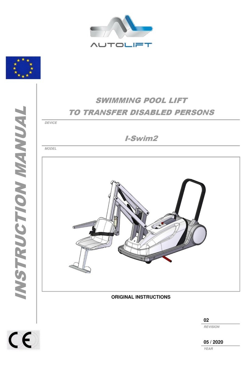
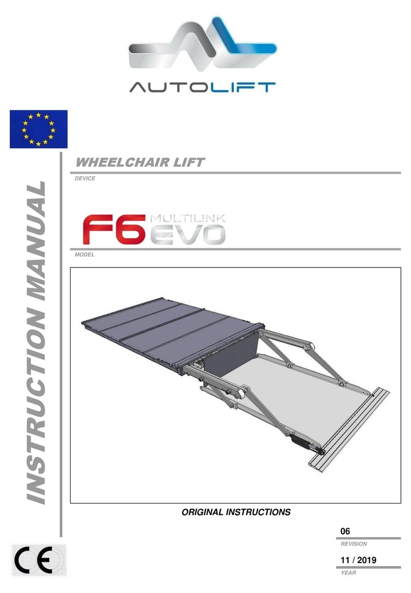
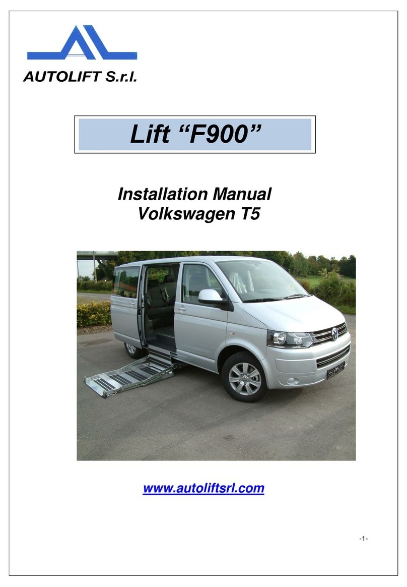
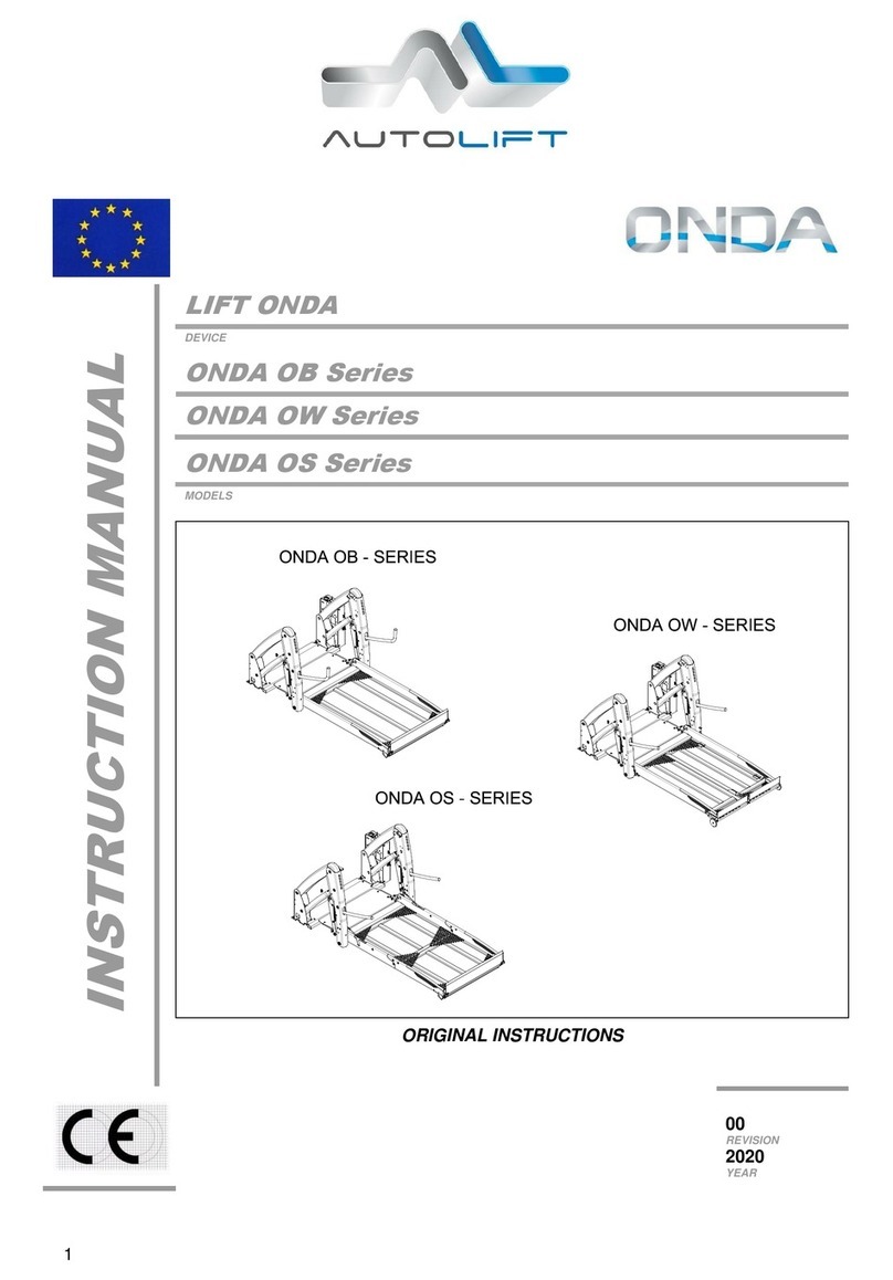
AUTOLIFT BB Series User manual

TABLE OF CONTENTS
Lift
DEVICE
BB –SKY –BBW
MODEL
1
INSTRUCTION MANUAL
LIFT
DEVICE
BB series 1150 –1350 –1370 –1401
SKY series: 1000M –1150L –1250 –1395 –1400
BBW series: 905M –1030L –1350 –1600
MODELS
ORIGINAL INSTRUCTIONS
00
REVISION
2015
YEAR
BB SERIES
SKY SERIES
BBW SERIES

TABLE OF CONTENTS
Lift
DEVICE
BB –SKY –BBW
MODEL
2
1. GENERAL WARNINGS .............................................................................................................3
1.1 MANUFACTURER......................................................................................................................3
1.2 MARKING...................................................................................................................................3
1.3 IDENTIFICATION OF OPERATORS..........................................................................................4
1.4 STRUCTURE AND USE OF THE MANUAL ...............................................................................5
1.5 SAFETY –GENERAL RULES....................................................................................................7
2. GENERAL DESCRIPTION.........................................................................................................9
2.1 COMPONENTS..........................................................................................................................9
2.2 DIMENSIONS...........................................................................................................................10
2.3 TECHNICAL DATA...................................................................................................................12
3. FIELD OF USE ………..………………………………………………………………………………..13
3.1 INTENDED USE.......................................................................................................................13
3.2 IMPROPER USE......................................................................................................................13
4. SAFETY DEVICES...................................................................................................................14
5. WARNING SIGNS....................................................................................................................15
6. INSTALLATION .......................................................................................................................16
6.1 RECEIPT AND INSPECTION...................................................................................................16
6.2 STORING AND NON-USE OF THE LIFT .................................................................................16
6.3 TRANSPORT ...........................................................................................................................17
6.4 HANDLING...............................................................................................................................18
6.5 INSTALLATION ON A VEHICLE ..............................................................................................18
7.1 NORMAL USE..........................................................................................................................19
7.2 USE IN EMERGENCY CONDITIONS.......................................................................................21
7.2.1 UP - CLOSING.........................................................................................................................21
7.2.2 OPENING - DOWN...................................................................................................................22
8. CLEANING...............................................................................................................................23
9. MAINTENANCE.......................................................................................................................24
9.1 PERIODIC INSPECTION..........................................................................................................24
9.2 FREQUENCY OF CONTROLS.................................................................................................25
10. DEMOLITION AND DISPOSAL ...............................................................................................26
11. TROUBLESHOOTING .............................................................................................................27
12. WIRING DIAGRAM ..................................................................................................................29
13. HYDRAULIC DIAGRAM...........................................................................................................30
14. SPARE PARTS........................................................................................................................31

GENERAL WARNINGS
1
Lift
DEVICE
BB –SKY –BBW
MODEL
3
1.1 MANUFACTURER
AUTOLIFT SRL
Via Trentin 8 –46020 Pegognaga (MN) - Italy
Tel. +39 0376 550375 –info@autoliftsrl.com
1.2 MARKING
The lift device is manufactured in compliance with the relevant EC directives applicable on the date of
entering the market. Considered a "medical device" pursuant to article 2, point 1), letter a), first
paragraph of directive 2007/47/EC, the device carries a specific identification plate which, in addition to
the specific technical data also includes the CE marking, guarantee of the compliance of the device to
the directives/standards referred to the enclosed Declaration of Conformity.
The plate, a facsimile of which is shown here, is stamped with the data indicating the specific model and
unit.
CUSTOMER NAME:
INSTALLER NAME:
DATE OF INSTALLATION:
SERIAL NUMBER:
IT IS PROHIBITED TO REMOVE OR TAMPER WITH THE
IDENTIFICATION PLATE.

GENERAL WARNINGS
1
Lift
DEVICE
BB –SKY –BBW
MODEL
4
1.3 IDENTIFICATION OF OPERATORS
The lift user is the physical or legal person who purchases it and has it operated by
an operator.
The operator, also defined as the accompanying person, is the person who uses
the device.
Operators working with devices designed to transport persons with motor deficiencies or disabilities must
be competent to act in all situations; they must always be mentally aware; they must comply with the
physical and mental requirements for ensuring sufficient reactivity in the event of an emergency or a
hazard. They shall therefore not only acknowledge all the details given in this manual but shall
obligatorily possess the following characteristics.
PHYSICAL: good eyesight, hearing, coordination, ability to safely perform all the functions required to
use the lift, no disorders or debilitating or disabling infirmities caused by the intake of substances altering
the person's emotional state (e.g. drugs and/or alcohol).
MENTAL: ability to understand and apply the established rules and safety precautions; they shall be
attentive, use common sense to ensure their own safety and that of others; they shall be willing to
correctly and responsibly perform the tasks of assistant and operator during the transport, loading and
unloading of disabled and other passengers.
EMOTIONAL: the operator must be calm and able to cope with stress and use common sense over his
own physical and mental conditions; he must be able to manage normal and abnormal situations,
understanding his own limits and, at the same time, how to deal with an emergency.
TRAINING: this manual, and diagrams and graphs attached, the hazard warning plates and stickers
applied to the electro-hydraulic lift must be read, studied and fully understood; the operator must be
familiar with the use of the controls and the lift movements, having performed all tests (without loads)
required to learn all the operating phases.
TASKS AND RESPONSIBILITIES: in this context we refer only to the operator's tasks concerning the
use of the lift, which include switching on the power circuit, moving the various parts, assembly and
removal of any optional parts, and maintenance. The operator must therefore be fully familiar with the
safety regulations and relative devices, the use of the controls and the manual emergency devices.
The operator is personally responsible for the use of the lift and its correct operation, maintenance, the
handled load and all actions which are performed within the above-listed tasks.
If any situations occur which could compromise the physical and mental state of the transported person,
following the non -compliance or poor knowledge of the operator, he shall personally be civilly and
criminally liable towards the injured party.
This applies also to any tampering or modifications by the operator of parts or components of the lift
which no longer guarantee its safety and reliability for the transported persons.
Autolift Srl declines all liability in the event of such situations.

GENERAL WARNINGS
1
Lift
DEVICE
BB –SKY –BBW
MODEL
5
The user is responsible for distributing this manual to all staff working with the lift.
In addition to complying strictly with the instructions given in this manual, operators
shall not use the lift and shall report directly to their managers, or if they do not have
one, directly to the manufacturer AUTOLIFT srl, concerning any shortcomings or
potentially hazardous situation which may occur.
1.4 STRUCTURE AND USE OF THE MANUAL
USERS AND OPERATORS MUST HAVE READ THIS MANUAL PRIOR
TO PUTTING THE LIFT INTO SERVICE.
The manual includes images of the SKY model, which are also representative of the
BB and BBW series.
This manual aims to provide users and operators with all the information they require to ensure that they
are able both to use the lift appropriately and are able to manage it as autonomously and safely as
possible.
Before performing any operations on the lift, users and operators must carefully read the instructions
given in this publication.
In the event of doubt over the correct interpretation of the instructions, contact the AUTOLIFT srl
technical department to obtain the required clarifications.
This manual is an integral part of the lift, it must be kept safely by the purchaser and made available for
use by the operators.
The contents of this manual comply with the Directive 2007/47/EC and were drafted following the
guidelines given in UNI 10893:2000. They also comply with the requirements of UNI EN ISO
10535:2007.
This manual has 33 pages, including the cover, and enclosures (see para.1.6).
Data and drawings are indicative only; with a view to the continuous development and updating of its
products, the manufacturer may modify the contents without notice.
It is prohibited to disclose, edit or use this manual for any other purposes.
In drafting the manual, we have chosen to use only a few yet clear pictograms to draw the reader's
attention to important concepts and to make consultation simpler and more immediate.

GENERAL WARNINGS
1
Lift
DEVICE
BB –SKY –BBW
MODEL
6
THE INDICATIONS MARKED BY THIS SYMBOL REPRESENT A
POTENTIAL HAZARD, WITH THE RISK OF PHYSICAL DANGER FOR
THE USERS.
THE INDICATIONS MARKED BY THIS SYMBOL ARE DEEMED
PARTICULARLY IMPORTANT FOR THE OPERATION OF THE LIFT.
THE INDICATIONS MARKED WITH THIS SYMBOL ARE IMPORTANT
FOR COMMUNICATION BETWEEN THE MANUFACTURER AND THE
USER.

GENERAL WARNINGS
1
Lift
DEVICE
BB –SKY –BBW
MODEL
7
1.5 SAFETY –GENERAL RULES
When using the hydraulic lift, a hazardous situation may be caused by parking the
vehicle on a slope.
Use the lift with the vehicle parked on flat ground
The vehicle must always be parked safely with the emergency brakes on, before
starting to work the lift.
Examine the hydraulic lift carefully before each use. If there are any hazardous
conditions or if you notice unusual noises or movements, do not use the lift and
contact an Autolift agent or authorised workshop for the necessary inspections and
repairs.
Read and comply with the labels and warning symbols fixed to the hydraulic lift or
near the loading area of the vehicle used to transport wheelchairs.
When using the hydraulic lift, the occupant of the wheelchair should where possible
face outwards; i.e. with the larger wheels facing the vehicle.

GENERAL WARNINGS
1
Lift
DEVICE
BB –SKY –BBW
MODEL
8
Make sure that the wheelchair is placed securely on the platform and does not
extend over the edge or interfere with the operation of the anti-roll device.
Do not work the platform with a load of over 350 kg.
DO NOT PLACE ARMS, LEGS OR CLOTHING NEAR THE MOVING OR
PROTRUDING PARTS OF THE PLATFORM.
RISK OF CRUSHING AND SHEARING
Unauthorised persons must not stand nearby during the use of the lift, and must not
stand between the vehicle and the platform, even for quick checks with the platform
at a standstill. These checks and adjustments must be performed exclusively by
authorised Autolift staff.

GENERAL DESCRIPTION
2
Lift
DEVICE
BB –SKY –BBW
MODEL
9
2.1 COMPONENTS
1
Vehicle fixing base
6
Front flap
2
Jointed drive arms
7
Gripper handles
3
Hydraulic power unit
8
Rear flap
4
Drive cylinders
9
Safety microswitch and cam
5
Load platform
The drawing shown represents all models: BB –SKY –BBW
1
3
2
4
5
6
7
8
9

GENERAL DESCRIPTION
2
Lift
DEVICE
BB –SKY –BBW
MODEL
10
2.2 DIMENSIONS
The drawing shown represents all models: BB –SKY –BBW

GENERAL DESCRIPTION
2
Lift
DEVICE
BB –SKY –BBW
MODEL
11
BB
1150
BB
1350
BB
1370
BB
1401
A
1140
1140
1240
1240
B
1030
1030
1130
1130
C
920
920
920
920
D
1250
1470
1500
1520
E
310
310
310
310
F
340
340
340
340
G
1150
1350
1370
1400
SKY
1000M
SKY
1150L
SKY
1250
SKY
1395
SKY
1400
A
968
1070
1140
1140
1240
B
851
950
1030
1030
1130
C
690
880
920
920
920
D
980
1125
1220
1220
1220
E
310
310
310
310
310
F
350
350
350
350
350
G
970
1150
1250
1400
1400
BBW
905M
BBW
1030L
BBW
1350
BBW
1600
A
968
1070
1140
1140
B
851
950
1030
1030
C
690
880
920
920
D
1018
1160
1470
1720
E
310
310
310
310
F
420
420
580
580
G
902
1030
1350
1600

GENERAL DESCRIPTION
2
Lift
DEVICE
BB –SKY –BBW
MODEL
12
2.3 TECHNICAL DATA
BB
1150
BB
1350
BB
1370
BB
1401
Capacity
Kg
350
350
350
350
Weight
Kg
142
147
149
151
Power supply
Volt
12-24
12-24
12-24
12-24
Max. pressure
bars
140
140
140
140
Platform
mm
1150X800
1350X800
1370X800
1400X900
Max. overhang
mm
920
920
920
920
Aux emergency pump
YES
YES
YES
YES
Airborne noise
dB(A)
< 70
< 70
< 70
< 70
SKY
1000M
SKY
1150L
SKY
1250
SKY
1395
SKY
1400
Capacity
Kg
300
320
320
320
320
Weight
Kg
100
105
142
147
151
Power supply
Volt
12-24
12-24
12-24
12-24
12-24
Max. pressure
bars
140
140
140
140
140
Platform
mm
970x620
1150x720
1250x800
1400x800
1400x900
Max. overhang
mm
690
920
920
920
920
Aux emergency pump
YES
YES
YES
YES
YES
Airborne noise
dB(A)
< 70
< 70
< 70
< 70
< 70
BBW
905M
BBW
1030L
BBW
1350
BBW
1600
Capacity
Kg
300
320
350
350
Weight
Kg
100
110
145
165
Power supply
Volt
12-24
12-24
12-24
12-24
Max. pressure
bar
140
140
140
140
Platform
mm
902x645
1030X740
1350X800
1600X800
Max. overhang
mm
690
880
920
920
Aux emergency pump
SI
SI
SI
SI
Airborne noise
dB(A)
< 70
< 70
< 70
< 70
.

FIELD OF USE
3
Lift
DEVICE
BB –SKY –BBW
MODEL
13
3.1 INTENDED USE
The lift is designed for installation on the loading floor of a vehicle designed for transportation of the
disabled in wheelchairs, within the limits of the performances and capacities indicated in the technical
characteristics.
The lift must only be used by an authorised and trained operator, known as the accompanying person,
who possesses the knowledge and physical requirements to safely perform operations with disabled
persons.
3.2 IMPROPER USE
Anything that is not explicitly referred to in chapter 3.1 is considered IMPROPER USE.
IT IS FORBIDDEN to climb onto the lift or any of its parts and go up or down while
standing.
IT IS FORBIDDEN to use the lift to transport animals or objects.
IT IS FORBIDDEN to use the lift with the vehicle not parked on a flat surface.
THE MANUFACTURER DECLINES ALL RESPONSIBILITY FOR
DAMAGE CAUSED TO PERSONS OR PROPERTY OR TO THE LIFT
ITSELF DUE TO ANY USE OTHER THAN THAT DESCRIBED IN THIS
MANUAL.

SAFETY DEVICES
4
Lift
DEVICE
BB –SKY –BBW
MODEL
14
1
Gripper handles for the disabled passenger
2
Internal stop flap
3
Load and stop flap for lifting
4
Hydraulic power unit safety devices:
a) Overload limit valve
b) Anti-tipping pressure switch
5
Guard
IT IS FORBIDDEN TO ELIMINATE, REMOVE OR TAMPER WITH THE
EXISTING SAFETY SYSTEMS.
The anti-tipping pressure switch prevents the platform from closing when occupied
by a wheelchair.
1
2
3
4
5

WARNING SIGNS
5
Lift
DEVICE
BB –SKY –BBW
MODEL
15
THE LIFT HAS THE FOLLOWING MARKINGS
Do not lubricate, clean or adjust the device
while moving
Do not remove the guards
Risk of crushing
IT IS FORBIDDEN TO TAMPER WITH/REMOVE THE MARKINGS.

INSTALLATION
6
Lift
DEVICE
BB –SKY –BBW
MODEL
16
6.1 RECEIPT AND INSPECTION
On receipt of the lift, you must perform the following inspections:
-Check that the supply corresponds to the specifications ordered and the transport document.
-Check that the packaging is intact and that no parts have been broken or damaged during
transportation.
-Carefully check that the devices have not been damaged during transportation and that no parts
have been removed and/or tampered with.
-Check that all documentation necessary for installation has been provided.
IF THE DELIVERED DEVICE DOES NOT COMPLY WITH THESE
REQUIREMENTS, NOTIFY THE MANUFACTURER IMMEDIATELY.
6.2 STORING AND NON-USE OF THE LIFT
If the lift is not used, proceed as follows:
-Store the lift in a sheltered area away from atmospheric agents.
-All electrical / electronic parts must be kept wrapped to protect from humidity.
-The storage temperature must be between +5°C and +50°C.
-All sliding parts (guides, cylinders…) must be protected from dust and rust.
-Do not store for over 6 months. For longer periods of storage, before putting into service contact
the manufacturer to have the lift conditions inspected.
STORAGE OF THE LIFT IN CONDITIONS THAT DO NOT COMPLY
WITH THE ABOVE DESCRIPTION SHALL NULLIFY THE WARRANTY
FOR ANY PARTS TO BE REPLACED.

INSTALLATION
6
Lift
DEVICE
BB –SKY –BBW
MODEL
17
6.3 TRANSPORT
The lift must be transported using a vehicle (van, lorry, etc.) of an appropriate size and capacity.
The lift is shipped by the manufacturer packaged in a cardboard box or wooden crate anchored to a
wooden pallet.
\
PALLET
VOLUME CC
CARTON
PALLET
VOLUME CC
1 model BB (1401)
50x130x165
1072
40x130x175
910
2 models BB (1401)
80x120x165
1584
/
/
1 model BB (1350)
50x130x150
975
40x130x175
910
1 model SKY
50x130x140
910
45x120x140
756
2 models SKY
80x120x140
1344
/
/
1 model BBW
50x130x150
975
40x130x175
910
2 models BBW
80x120x150
1440
/
/
1 model BBW (L)
50x130x140
910
45x120x140
756
2 model BBW (L)
80x120x140
1248
/
/
For the weight of each model, refer to the Technical Data chapter

USE
7
Lift
DEVICE
BB –SKY –BBW
MODEL
18
6.4 HANDLING
The packaged lift must be handled by a transpallet, fork lift
truck, etc.
The means used for safe handling must have a load
capacity suited to the load to be transported (see weight
indicated in the Technical Data table).
HANDLING STAFF MUST WEAR: SAFETY SHOES WITH STEEL TOE
CAP AND NON-SLIP SOLES.
MAKE SURE THAT NO UNAUTHORISED PERSONS ARE STANDING
WITHIN THE RADIUS OF ACTION OF THE LIFTING/HANDLING MEANS
(FORK LIFT TRUCK, TRANSPALLET, ETC.) DURING THE LIFTING,
TRANSPORT AND HANDLING OPERATIONS.
If a cardboard box has been used for packaging, to unpack the lift, cut the cardboard packaging with a
stanley knife (max. blade length 1 cm) on the 4 sides of the base of the packaging, then lift and remove.
Otherwise, if a wooden crate has been used, remove the nails from the wooden crate starting from the
top and then remove the side walls.
STAFF REMOVING THE PACKAGING MUST WEAR: SAFETY SHOES
WITH STEEL TOE CAP AND NON-SLIP SOLES AND GLOVES.
6.5 INSTALLATION ON A VEHICLE
Installation on a vehicle must be performed exclusively by Autolift staff or authorised
installers.
Autolift declines all liability to damage to persons, property or the machine due to
installation on a vehicle not performed by authorised persons.

USE
7
Lift
DEVICE
BB –SKY –BBW
MODEL
19
7.1 NORMAL USE
The AUTOLIFT SKY electro-hydraulic lift control is a wired portable remote control known as push-
button panel, equipped with two round protruding buttons indicating the two operating states.
The fundamental purpose of the push-button panel is to control the four distinct lift operations (open -
down - up - close) in just two control buttons.
This is done by a special electrical system which uses a timer-operated consent technology. Simply and
safely it prevents you from having to change button for every different lift movement and from entering
the wrong command.
Hold down the lower button (down arrow)
and the lift opens from the vertical
stowage position to rest in a horizontal
position parallel to the floor of the vehicle
it is installed on.
After opening, the lift stops automatically.
To lower the lift to the ground, press the
down arrow button again: the platform
descends slowly to the ground (the anti-
roll device lowers automatically when the
platform touches the ground).
To raise the lift, press and hold down the
button with the up arrow, in the upper part
of the push-button panel.
The anti-roll device rises automatically
when the platform lifts off the ground.

USE
7
Lift
DEVICE
BB –SKY –BBW
MODEL
20
The lift stops automatically when it
reaches the height of the floor of the
vehicle.
To stow the platform in the vertical
position in the installation compartment
press the button with the up arrow again.
This manual suits for next models
15
Table of contents
Other AUTOLIFT Lifting System manuals
Popular Lifting System manuals by other brands

Norco
Norco 82306 Setup, operating, maintenance instructions
ELS LIFT
ELS LIFT 5.5 Junior SP user manual
Sirio Antenne
Sirio Antenne SRH 370.32 EX user manual
Snorkel
Snorkel AB85J Repair parts manual
Stratus
Stratus SAE-F14X Installation, operation & maintenance instructions
The Handy
The Handy 10740G Instructions & parts book

Bolton Tools
Bolton Tools HP-L4G Installation, operation & maintenance manual
Ravas
Ravas iForks user manual
mydocking.com
mydocking.com L300 installation manual

ServerLIFT
ServerLIFT SL-350X Operator's manual
Tuxedo
Tuxedo TP9KACX Installation & operation manual

ReadyLift
ReadyLift 44-19620 instruction manual

