AutomationDirect igus XYZ Gantry User manual

Page 1igus XYZ Gantry User Manual – 1st Ed – 09/14/2022
igus XYZ gantrY user Manual

Page 2igus XYZ Gantry User Manual – 1st Ed – 09/14/2022
igus XYZ gantrY user Manual
CONTENTS
Getting Started � � � � � � � � � � � � � � � � � � � � � � � � � � � � � � � � � � � � � � � � � � � � � � � � � � � � � � � 3
Unpacking � � � � � � � � � � � � � � � � � � � � � � � � � � � � � � � � � � � � � � � � � � � � � � � � � � � � � � � � � � 3
Adjusting Carriage Block Clearance � � � � � � � � � � � � � � � � � � � � � � � � � � � � � � � � � � � � � � � � � � � 3
T-Slot Nuts � � � � � � � � � � � � � � � � � � � � � � � � � � � � � � � � � � � � � � � � � � � � � � � � � � � � � � � � � � 4
Linear Actuator Mounting � � � � � � � � � � � � � � � � � � � � � � � � � � � � � � � � � � � � � � � � � � � � � � � 5
Actuator Clamps� � � � � � � � � � � � � � � � � � � � � � � � � � � � � � � � � � � � � � � � � � � � � � � � � � � � � � � 5
Gantry Accessories � � � � � � � � � � � � � � � � � � � � � � � � � � � � � � � � � � � � � � � � � � � � � � � � � � � � � 6
Mounting Clamps � � � � � � � � � � � � � � � � � � � � � � � � � � � � � � � � � � � � � � � � � � � � � � � � � � � � � 6
Carriage Plate Adapter � � � � � � � � � � � � � � � � � � � � � � � � � � � � � � � � � � � � � � � � � � � � � � � � � � 6
Angle Brackets � � � � � � � � � � � � � � � � � � � � � � � � � � � � � � � � � � � � � � � � � � � � � � � � � � � � � � � 6
Motor Bracket Assembly � � � � � � � � � � � � � � � � � � � � � � � � � � � � � � � � � � � � � � � � � � � � � � � � 7
SAW Series (Lead Screw Driven) � � � � � � � � � � � � � � � � � � � � � � � � � � � � � � � � � � � � � � � � � � � � � 7
ZLW Series (Belt Driven) � � � � � � � � � � � � � � � � � � � � � � � � � � � � � � � � � � � � � � � � � � � � � � � � � � 8
Sensor Attachment � � � � � � � � � � � � � � � � � � � � � � � � � � � � � � � � � � � � � � � � � � � � � � � � � � � � 9
SAW Series Assembly/Disassembly� � � � � � � � � � � � � � � � � � � � � � � � � � � � � � � � � � � � � � � � �10
SAW Lead Nut Replacement� � � � � � � � � � � � � � � � � � � � � � � � � � � � � � � � � � � � � � � � � � � � � �12
ZLW Series Assembly/Disassembly � � � � � � � � � � � � � � � � � � � � � � � � � � � � � � � � � � � � � � � � �13
ZLW Series Belt Tensioning � � � � � � � � � � � � � � � � � � � � � � � � � � � � � � � � � � � � � � � � � � � � � �16
Bearing Block Alignment Procedure (All Models) � � � � � � � � � � � � � � � � � � � � � � � � � � � � � � �17
Bearing Block Liner Replacement (All Models)� � � � � � � � � � � � � � � � � � � � � � � � � � � � � � � � �18
ZLW Dual X Connecting Shaft � � � � � � � � � � � � � � � � � � � � � � � � � � � � � � � � � � � � � � � � � � � � �19

Page 3igus XYZ Gantry User Manual – 1st Ed – 09/14/2022
igus XYZ gantrY user Manual
Getting Started
Unpacking
All linear actuators have mounting clamps included in the box. These can be used to secure the linear actuator
to a frame. Ensure the clamps are found and removed from the packaging before disposal of the box and packing
materials. There are 10 clamps included with each actuator (shown below).
Remove the orange quality inspection tag before using. Handle the linear actuator on the ends to avoid damage to
the bearing rails and carriage drive components.
The carriage of the ZLW series will have a slight stiffness to movement due to the storage of the belt in a fixed
position. This is normal and will diminish as the carriage is stroked back and forth exercising the belt.
Adjusting Carriage Block Clearance
All igus linear actuators are assembled with Adjustable Carriage Blocks to optimize side-to-side movement of the
Carriage. As the 4 adjustment screws are tightened the clearance between the bearing material and the guide rails
is reduced. The amount of adjustment depends on the application needs. Lower clearances give better holding
position when external loads are applied. But as the clearance decreases so does the resistance to linear travel,
therefore requiring more applied torque from the drive system. Typical clearance adjustment is a balance between
the two affects and becomes more of a judgement call rather than a calculated/measured value.
The adjustment is made by turning the brass set screw on each of the 4 bearing blocks.
• Use 1.5mm Allen wrench
• Clockwise = LESS Clearance
• Counter-Clockwise = MORE Clearance
• Turn 1 ‘click’ at a time, on each of the 4 bearing blocks, for best results
• Stroke the carriage assembly after each ‘click’ of adjustment and note the carriage travel resistance as well as
side-to-side movement.
NOTE: The adjustment set screw is brass. Do apply excessive torque or damage may occur to its threads or hex
socket.

Page 4igus XYZ Gantry User Manual – 1st Ed – 09/14/2022
igus XYZ gantrY user Manual
T-Slot Nuts
All igus linear actuators have 8 pre-installed t-slot nuts, M5-0.8, 4 each side. Remove the shipping set screws for
freedom of movement along the T-slot.
Page 5igus XYZ Gantry User Manual – 1st Ed – 09/14/2022
igus XYZ gantrY user Manual
Linear Actuator Mounting
Actuator Clamps
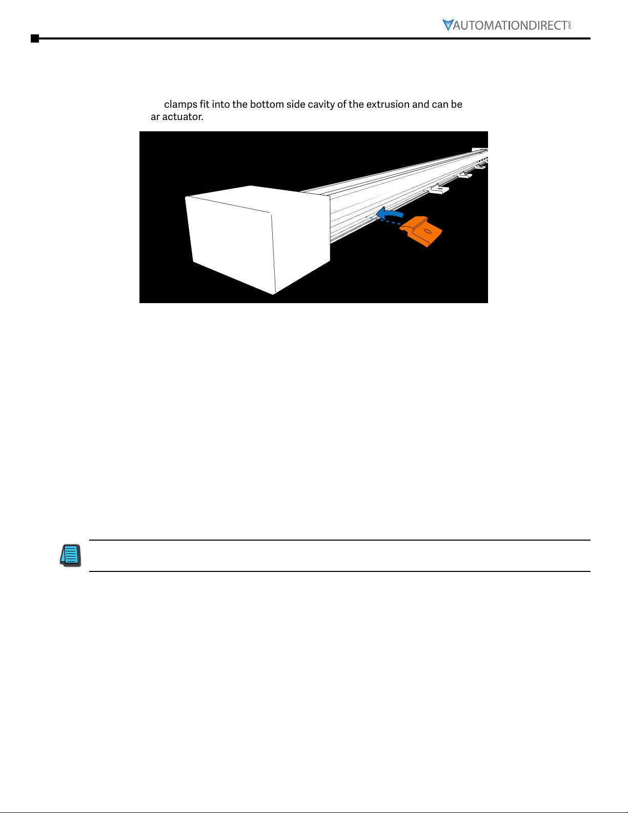
The included mounting clamps fit into the bottom side cavity of the extrusion and can be positioned anywhere along
the length of the linear actuator.
NOTE: Not all included mounting clamps may be needed.

Page 6igus XYZ Gantry User Manual – 1st Ed – 09/14/2022
igus XYZ gantrY user Manual
Gantry Accessories
Mounting Clamps
A-ZSY-104026 kit includes:
• 2 Mounting Clamps
• 6 SHCS M6-1.0 x 12mm
Carriage Plate Adapter
A-SWY108003150 kit includes:
• 2 Plate Adapters
• 8 Low Profile SHCS M6-1.0 x 20mm
Angle Brackets
A-AK-0026 kit includes:
• 2 Angle Brackets
• 4 SHCS M6-1.0 x 20mm
• 8 SHCS M5-0.8 x 10mm
• 8 T-slot nuts M5-0.8
Page 7igus XYZ Gantry User Manual – 1st Ed – 09/14/2022
igus XYZ gantrY user Manual
Motor Bracket Assembly
The motor brackets are designed to mount specific motor sizes. They include all of the necessary mounting
hardware for the particular motor. The drive coupling is not part of the motor bracket kit and must be purchased
separately. It is best practice to assemble the motor to the linear actuator with it in the vertical orientation.
SAW Series (Lead Screw Driven)
Motor
Bracket PN
Bracket to
Actuator Fastener
Motor to Bracket
Fastener
Recommended ADC Drive Couplings
Coupling Jaw for
Actuator Coupling Jaw
for Motor Coupling Spider
1040 1080
STP17-SAW
SHCS M4-0.7 x 8mm
(x4)
SHCS M3-0.5 x 6mm (x4)
SJCA-30C-10 SJCA-30C-8
SJCA-30C-5
SJC-30-RD-SLEEVE
STP23-SAW SHCS M5-0.8 x 10mm (x4) SJCA-30C-6.35
SVL201-SAW SHCS M4-0.7 x 8mm (x2) SJCA-30C-8
SVL202-SAW SHCS M5-0.8 x 12mm (x4) SJCA-30C-14

Page 8igus XYZ Gantry User Manual – 1st Ed – 09/14/2022
igus XYZ gantrY user Manual
ZLW Series (Belt Driven)
Motor
Bracket PN
Bracket to Actuator
Fastener
Motor to Bracket
Fastener
Recommended ADC Drive Couplings
Coupling Jaw
for Actuator
Coupling Jaw
for Motor Coupling Spider
STP17-ZLW
Shoulder Screw
Ø6 x M5-0.8 x 20mm (x4)
SHCS M3-0.5 x 14mm (x4)
SJCA-30C-10
SJCA-30C-5
SJC-30-RD-SLEEVE
STP23-ZLW SHCS M5-0.8 x 10mm (x4) SJCA-30C-6.35
SVL201-ZLW SHCS M4-0.7 x 8mm (x2) SJCA-30C-8
SVL202-ZLW SHCS M5-0.8 x 10mm (x4) SJCA-30C-14

Page 9igus XYZ Gantry User Manual – 1st Ed – 09/14/2022
igus XYZ gantrY user Manual
Sensor Attachment
Sensors can be attached to the side T-slots of the linear actuator using the pre-installed T-slot nuts. The carriage
block will act as the flag when an ADC proximity sensor is mounted on the sensor bracket. Mounting hardware is
included with the sensor bracket kit.
NOTE: The linear actuator end blocks should not be used as hard stops. Sensors should be mounted at both
ends of stroke for a controlled stop. Best control practice is to use Normally Closed (NC) for this purpose.
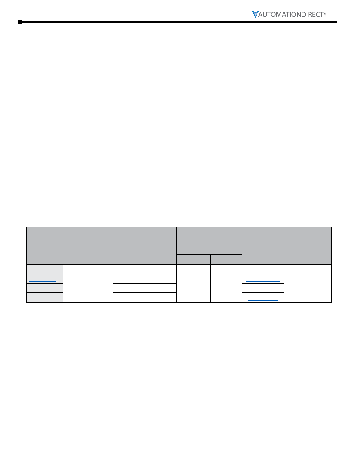
RECOMMENDED ADC INDUCTIVE PROX SENSORS
Sensor PN Switch Normal State
P8-AN-1F NPN N.O.
P8-AN-2A NPN N.O.
P8-CN-1A NPN N.C.
P8-AP-1F PNP N.O.
P8-AP-2F PNP N.O.
P8-CP-1F PNP N.C.
P8-CP-2F PNP N.C.

Page 10igus XYZ Gantry User Manual – 1st Ed – 09/14/2022
igus XYZ gantrY user Manual
SAW Series Assembly/Disassembly
The following assembly steps can be followed in the reverse order for disassembly.
NOTE: Steps shown below are the same for both ends of the Actuator.
1. Loosen 4 screws on Carriage Plate.
2. Install Carriage Plate subassembly by aligning the Bearing Liners with the top rails and Lead Nut with the Lead
Screw. Lead Nut should be opposite side from the input shaft. Turn Lead Screw to engage with Lead Nut. This
will pull the Carriage Plate fully onto rails.
3. Gently install O-ring onto Lead Screw until seated into notch (SAW1040 only).
4. Install end block.

Page 11igus XYZ Gantry User Manual – 1st Ed – 09/14/2022
igus XYZ gantrY user Manual
5. Apply blue thread locking compound to the screws (x2 set screws for SAW1040 / x4 SHCS for SAW1080) and
install to secure end block.
6. Install shaft collar onto Lead Screw...
i. SAW1040–...turning clockwise with a flat blade screwdriver. Install the shaft collar such that the Lead Screw
turns freely with no lengthwise movement of the Lead screw drive subassembly. Turn Lead Screw to access
shaft collar screw and tighten.
ii. SAW1080–... until bearing is fully seated. Turn Lead Screw to access 1 shaft collar screw (socket head) and
slightly tighten. Rotate the Lead Screw 180° to access the 2nd shaft collar screw and slightly tighten. Check to
ensure Lead Screw turns freely with no lengthwise movement of the Lead screw drive subassembly. Alternate
tightening of the shaft collar screws until fully tightened. Finally, rotate lead screw to access shaft collar set
screw and tighten.

Page 12igus XYZ Gantry User Manual – 1st Ed – 09/14/2022
igus XYZ gantrY user Manual
SAW Lead Nut Replacement
1. SAW1040
i. Press down to remove old Lead Nut.
ii. Press new Lead Nut into hole in the Carriage Plate until fully seated.
2. SAW1080
i. Remove 4 M5-0.8 x 12mm SHCS to release Lead Nut and Retainer.
ii. Remove old Lead Nut and press in new Lead Nut with groove facing down.
iii. Replace Retainer and re-install screws.

Page 13igus XYZ Gantry User Manual – 1st Ed – 09/14/2022
igus XYZ gantrY user Manual
ZLW Series Assembly/Disassembly
The following assembly steps can be followed in the reverse order for disassembly.
NOTE: Steps shown below are the same for both ends of the Actuator.
1. Loosen 4 screws on the Carriage Plate.
2. Slide the Carriage Plate onto the Rails.
3. Install the End Stop onto the rails using 2 screws (Low Profile SHCS M4-0.7 x 10mm).
4. Insert Drive Pulley subassembly into the End Stop.

Page 14igus XYZ Gantry User Manual – 1st Ed – 09/14/2022
igus XYZ gantrY user Manual
5. Prepare the Idler Pulley by loosening the 4 Locking Set Screws by a few turns and tightening the Jack Screws all
the way in. If the Jack Screws don’t go all the way in, loosen the Locking Set screws further.
6. Insert the Idler Pulley subassembly into the End Stop with the Jack Screw going in first.
7. Insert the timing belt through the lower channel of both End Stops and wrap it around both pulleys.
8. Attach the timing belt to both ends of the Carriage Plate using the belt clamps and screws.
Actuator Part Number Replacement Belt
Length (mm)
ZLW1040S-2 / ZLW1080S-2 775
ZLW1040S-3 / ZLW1080S-3 975
ZLW1040S-4 / ZLW1080S-4 1175
ZLW1040S-5 / ZLW1080S-5 1375
ZLW1040S-6 / ZLW1080S-6 1575
ZLW1040S-8 / ZLW1080S-8 1975
ZLW1040S-10 / ZLW1080S-10 2375
Timing Belt Information
Material: Polyurethane with Steel Cords
Tooth Profile: AT5
Belt Width: 16mm
Belt Mass: 0.059 kg/m
Color: White

Page 15igus XYZ Gantry User Manual – 1st Ed – 09/14/2022
igus XYZ gantrY user Manual
9. Install the End Stop covers

Page 16igus XYZ Gantry User Manual – 1st Ed – 09/14/2022
igus XYZ gantrY user Manual
ZLW Series Belt Tensioning
1. Using a ‘Belt Tensioning Meter’ to measure belt tension, turn the 4 Jack Screws counter-clockwise to increase
belt tension. Turn the Jack Screws evenly in a crisscross pattern. To reduce belt tension turn the Jack Screws
clockwise.
i. Belt mass property = 0.059 kg/m
ii. Proper Belt Tension should be 200N
2. Once the proper belt tension is achieved, install 4 Locking Set Screws
3. Verify Belt Tension. If adjustment is needed, loosen the Locking Set Screws and repeat the above steps.
4. Install plastic End Caps

Page 17igus XYZ Gantry User Manual – 1st Ed – 09/14/2022
igus XYZ gantrY user Manual
Bearing Block Alignment Procedure (All Models)
1. Loosen 4 Screws on the Carriage Plate
2. Loosely install 4 M6-1.0 screws in open holes of Carriage Plate. These are temporary to ensure thread access for
attaching future parts to the Carriage Plate.
3. While applying a downward force on the center of the Carriage Plate, slightly tighten the 4 Carriage Plate screws
in a crisscross pattern.
4. Move and stroke the Carriage checking for smooth movement.
5. Repeat steps 3 and 4 until movement is as desired.
6. Remove the 4 M6-1.0 temporary screws.
7. With a rubber hammer, sharply hit the center of the Carriage Plate. This fully seats the Bearing Liner. This step
can be done any time, after installation or use, when the carriage seems to have resistance to motion.

Page 18igus XYZ Gantry User Manual – 1st Ed – 09/14/2022
igus XYZ gantrY user Manual
Bearing Block Liner Replacement (All Models)
The following assembly steps are performed after the Carriage Plate is removed from the Linear Actuator. For
reinstalling the Carriage Plate, please refer to the SAW or ZLW Assembly Steps.
NOTE: Follow the “Bearing Block Alignment Procedure (All Models)” on page 17 after the Linear Actuator is
fully assembled to ensure the new Bearing Block Liners are fully seated.
Important:
1. Gently turn each of the 4 Clearance adjustment set screws fully counter-clockwise
2. To remove Bearing Liner, push down on the tab and roll.
3. To install new Bearing Liner, drop in and roll until seated

Page 19igus XYZ Gantry User Manual – 1st Ed – 09/14/2022
igus XYZ gantrY user Manual
ZLW Dual X Connecting Shaft
1. When the 2 linear actuators are mounted, measure the distance between shaft ends (D)
2. The length of the connecting shaft (L) may need to be cut to accommodate the proper spacing for the Drive
Couplings. Use the following formula to calculate L.
i. (metric) L = D – 38 mm
ii. (imperial) L = D- 1.5”
NOTE: This formula is for AutomationDirect Drive Coupling SRBA-39C-10-10 only.
3. Cut Connecting Shaft, A-AWM-10-xxx to the proper length (L). If the Connecting Shaft is greater than 500mm,
use Pillow Block Support A-KSTM-10 midway along Connecting Shaft to minimize shaft whipping during high
speeds.
4. Slide 2 Drive couplings, and optional Pillow Block Supprt, onto the Connecting Shaft. Align this subassembly
with linear actuator drive shafts.
5. Slide the couplings onto the 2 drive shafts and tighten coupling clamp screws.
6. If the Connecting Shaft is out of alignment, adjust the mounting of the Linear Actuators to correct.
7. Slide the Connecting Shaft into position of 1 Drive Coupling and tighten clamp screw onto the drive shafts.
8. Move Carriages of both actuators to same end of stroke and tighten 2nd Drive Coupling clamp screw to
Connecting Shaft.
Table of contents
Other AutomationDirect Industrial Equipment manuals


Popular Industrial Equipment manuals by other brands


Siemens
Siemens Simatic Net Scalance M812 operating instructions

Shibuya Hoppmann
Shibuya Hoppmann Cap Star FCCPSTLDSA Installation & maintenance manual

Tecnosystemi
Tecnosystemi GALAXY STAR POINT user manual

SAelen TS
SAelen TS GS/PUMA 35D operating manual

Pulsar
Pulsar AWO200K Assembly instruction

Dover
Dover Civacon LM1051 ADJUSTMENT PROCEDURE


