AutomationDirect CLICK PLUS C2-01CPU Series User manual
1
3505 HUTCHINSON ROAD
CUMMING, GA 30040-5860
1-800-633-0405
C2-01CPU Series Quick Start Guide
www.automationdirect.com/clickplcs
Copyright© 2021, Automationdirect.com Incorporated/All Rights Reserved Worldwide
Before You Begin...
This guide provides a quick overview of installation and setup of your
CLICK PLUS CPU. It assumes some familiarity with the installation
and operation of industrial control equipment.
Please read and understand the information in this guide prior to
installation, operation, or servicing this equipment.
The CLICK PLUS User Manual provides full specifications and more
in-depth information on installation, setup,
programming and operation of the device. The
User Manual (C2-USER-M) is available in PDF
format by scanning this QR code or from https://
www.automationdirect.com/pn/doc/manual/
C2-USER-M. Extensive online help is also
available from within the CLICK software or at
https://www.automationdirect.com/clickplcs/free-software/
software-help.
What You’ll Need
CLICK PLUS CPU
PC with Click Software ver. 3.20 or later
24VDC power supply (SELV and Limited Energy)
(CLICK power supply C0-00AC or C0-01AC is recommended.)
Appropriate enclosure with vertical surface for DIN rail or surface mount
M4 screws, spring washers and flat washers if surface mounting
Ferrules and crimping tool for wire terminations (recommended)
Option Slot cover(s) (part #C2-FILL) are recommended if you are not
planning to use an Option Slot module. (Sold separately.)
Basic tools (screwdriver, wire stripper, etc.)
PLEASE REVIEW THE SAFETY WARNINGS ON THE
NEXT PAGE!
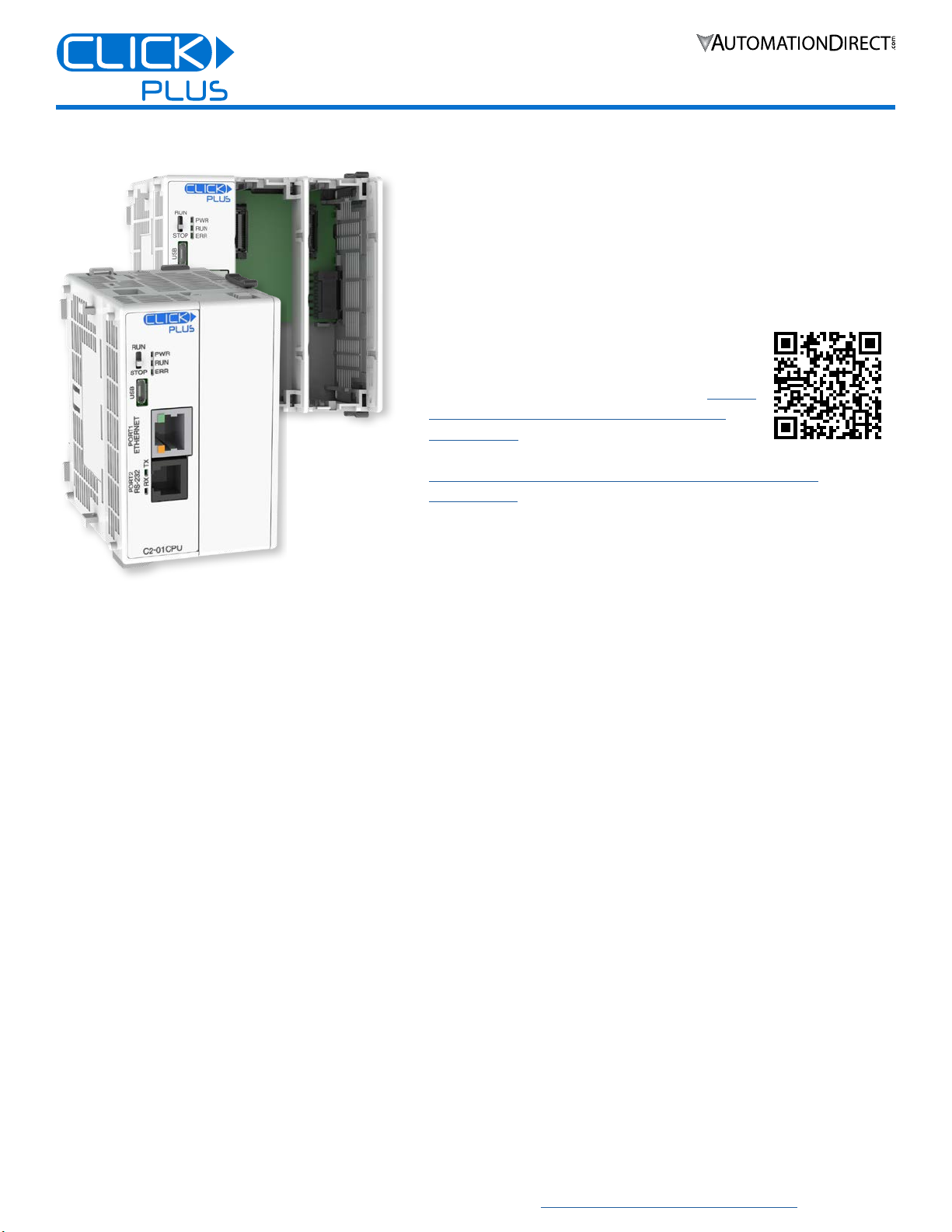
CLICK PLUS C2-01CPU(-x)
The CLICK PLUS C2-01CPU and
C2-01CPU-2 offer the lowest-cost entry
into our CLICK PLUS CPU family. They
provide all the computing power of the
CLICK PLUS line, and have USB, Ethernet
and RS-232 connectivity built in. The CPUs
are compatible with the full line of CLICK
PLUS Option Slot modules and CLICK
Stackable modules.
Key Features
Real Time Clock/Calendar
Battery backup (battery sold separately)
RS-232 port
microB USB port
RJ-45 Ethernet
Shown with optional C2-FILL
slot cover (sold separately)
2
3505 HUTCHINSON ROAD
CUMMING, GA 30040-5860
1-800-633-0405
C2-01CPU Series Quick Start Guide
www.automationdirect.com/clickplcs
Copyright© 2021, Automationdirect.com Incorporated/All Rights Reserved Worldwide
Safety Warnings
Please follow these instructions for personal and operational safety.
WARNING Assumes that incorrect handling may cause hazardous
conditions, resulting in severe injury or death.
CAUTION Assumes that incorrect handling may cause hazardous
conditions, resulting in medium or slight injury, or
may cause equipment damage.
WARNING
Don’t use this equipment in a flammable or explosive
environment in order to avoid accidental injury or fire.
You should use external electromechanical devices that are
independent of the PLC (Programmable Logic Controller)
system to provide protection for any part of the system;
otherwise malfunction or output failures may result in a
hazardous accident.
24VDC power is required from a secondary circuit or a specific
power supply unit only.
Ensure the Ground Terminal of the Power Supply (C0-00AC/
C0-01AC) for the CLICK PLUS CPU is connected to Earth
Ground to avoid electric shock or equipment damage during a
short circuit.
Don’t operate the equipment with a nonconforming external
power supply to avoid electric shock, equipment damage or fire.
Don’t intentionally fault the wiring; this may cause equipment
damage or fire.
To avoid electric shock or malfunctions which might result in an
accident, don’t touch any terminal while the PLC power is on.
Don’t put metals (e.g. screwdriver) into vent holes, or drop trash
or foreign objects (e.g. wire cut-offs) into the device, in order to
avoid electric shock or equipment damage.
If the equipment is used in a manner not specified by the
manufacturer, the protection provided by the equipment may be
invalidated.
CAUTION
For use in Pollution Degree 2 Environment. Use and store the
equipment in an environment described in the specifications
(regarding temperature, humidity, vibrations, shock, etc.) in
order to avoid equipment damage or fire.
Ensure all wiring has strain reliefs in order to avoid damage to
insulation that might result in electric shock or fire.
Ensure secondary external power circuits are only live after PLC
control program is started; otherwise a malfunction or output
failure may result in a hazardous accident.
Don’t block the vent holes. This may cause an increase of inter-
nal temperature resulting in equipment damage or fire.
Don’t disassemble or modify equipment so as to avoid electric
shock, equipment damage, or fire.
Cut off all phases of the external power source before mainte-
nance work, thus avoiding electric shock or equipment damage.
Hardware Installation
ENCLOSURES
It is important to select the appropriate enclosure to ensure
safe and proper operation of your CLICK PLUS PLC
system. Please use this product in a metal enclosure/cabinet.
Control applications vary and yours may require additional
considerations. At a minimum your enclosure should include:
Conformance to electrical standards
Protection from the elements in an industrial environment
Common ground reference
Maintenance of specified ambient temperature
Access to equipment
Security or restricted access
Sufficient space for proper installation and maintenance of
equipment
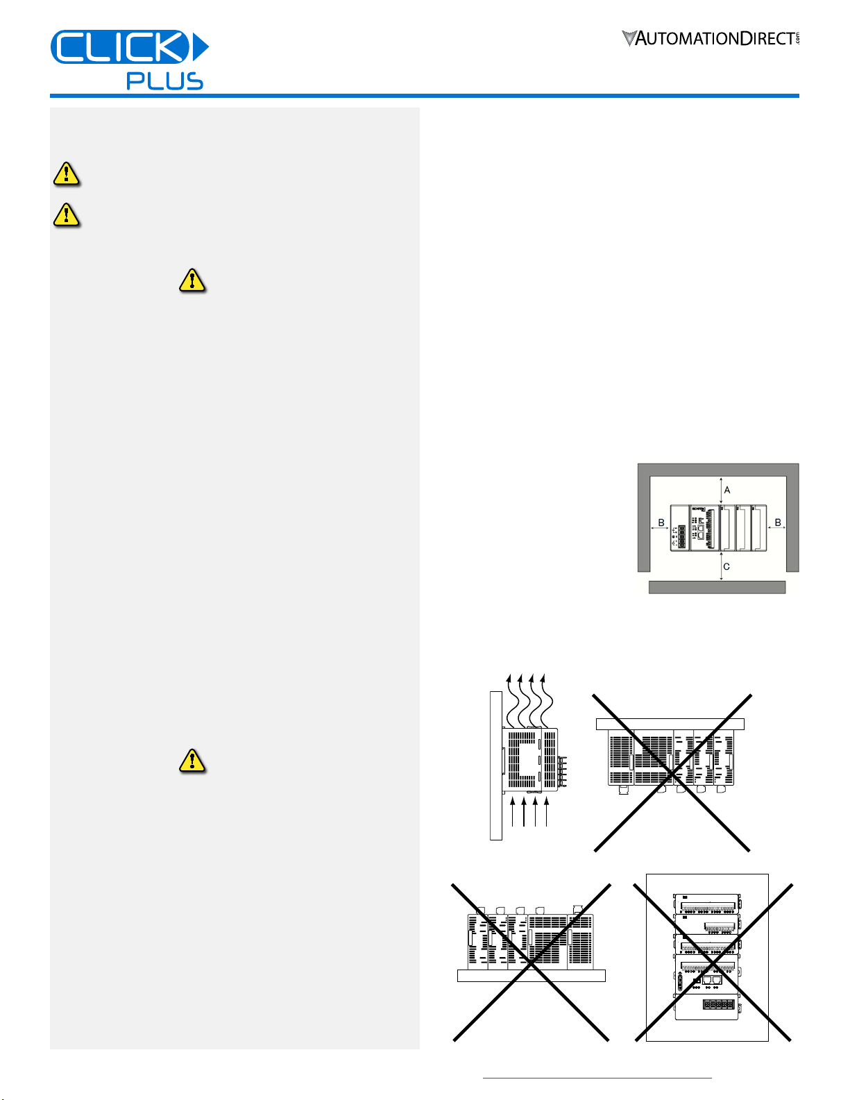
CLEARANCES AND ORIENTATION
Mount the unit horizontally to
provide proper ventilation.
There is a minimum clearance
requirement of 2in. (51mm)
from all sides of the cabinet and
the equipment.
There is a minimum clearance
requirement of 1.5 in. (38mm)
from the wiring ducts and the
equipment
Do not mount the unit upside down, on a horizontal surface, or
in a vertical arrangement.
Minimum clearance requirement
of 51mm for A, B, and C.
Air
Flow
TX2
PORT2
PORT1
RX2
RX1
TX1
PWR
ERR
RUN
STOP
RUN
Air
Flow
TX2
PORT2
PORT1
RX2
RX1
TX1
PWR
ERR
RUN
STOP
RUN
3
3505 HUTCHINSON ROAD
CUMMING, GA 30040-5860
1-800-633-0405
C2-01CPU Series Quick Start Guide
www.automationdirect.com/clickplcs
Copyright© 2021, Automationdirect.com Incorporated/All Rights Reserved Worldwide
Hardware Installation, continued
CAUTION
Discharge static electricity before installation or
wiring in order to avoid electric equipment damage.
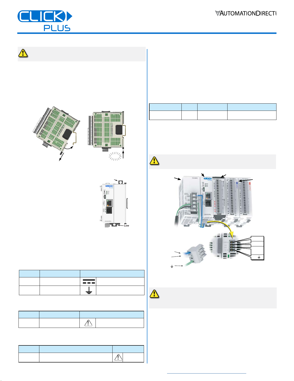
MOUNTING
The CLICK PLUS can be mounted on DIN rail or surface
mounted using built-in mounting tabs.
When installing on DIN
rails, always use end brackets
on both ends of assembly.
(AutomationDirect p/n DN-EB35)
Use 35mm width DIN Rails.
Use M4 size screws when you
surface mount.
Tighten the screws with a spring
washer and a small round washer
and torque 0.5 to 0.6 N·m.
Click
Pull tab
down.
Push tab
up until...
DIN Rail Mounting
Upper
Mounting Tab
Lower
Mounting Tab
Surface Mounting
WIRING
24VDC power is supplied to the CLICK PLUS CPU through
wiring connected from the power supply output to the 4-pin
connector located on the bottom of the CPU unit.
16–28 AWG wiring is supported. We recommend using
crimping ferrules on all wire terminations for a more secure
connection. The following crimping ferrules are recommend-
ed for the 24VDC power terminals.
Company
Type Model No. Compliant Wire
AutomationDirect
Ferrule V30AE000009
V30AE000041 0.2–0.5 mm2(22–26AWG)
* Maximum tightening torque is 0.22 to 0.25 N·m.
Take care not to contact adjacent terminal.
Please use SELV (as defined by UL61010-2-201) and Limited
Energy (as defined by UL61010-1, 9.4) power supply.
CLICK power supply C0-00AC or C0-01AC is recommended.
CAUTION
Do not operate without first installing safety
cover over power supply
leads.
CAUTION
DO NOT USE the PF connector. Leave this terminal
unconnected. Connecting the PF terminal to another
device may cause damage to the CLICK PLUS CPU.
24VDC
0V
PF
(future)
G
24VDC
0V
G
CLICK PLUS CPU
CLICK Power Supply
24VDC power is supplied to the CPU unit through wiring connected from
the power supply output to the 4-pin 24VDC input connector located on the
bottom of the CPU unit.
OPTION SLOT MODULE (OPTIONAL)
STACKABLE MODULES
(OPTIONAL)
I/O wiring is discussed in each module’s documentation.
Name
Description Symbol
DC
Direct current IEC6047 No. 5031
G
Functional earthing IEC6047 No. 5017
Name
Description Symbol
CAUTION
Safety instruction for
battery replacement ISO 7000 No.0434B
The symbol near the battery holder is indicated by the
following symbol.
Name
Description Symbol
CAUTION
• Refer to QR code link for product handling
• Use Copper Conductor Only
ISO 7000
No.0434B
The symbol on the product label is indicated by the
following symbol.
Power supply symbols listed on the equipment are indicated
by the symbols shown below.
4
3505 HUTCHINSON ROAD
CUMMING, GA 30040-5860
1-800-633-0405
C2-01CPU Series Quick Start Guide
www.automationdirect.com/clickplcs
Copyright© 2021, Automationdirect.com Incorporated/All Rights Reserved Worldwide
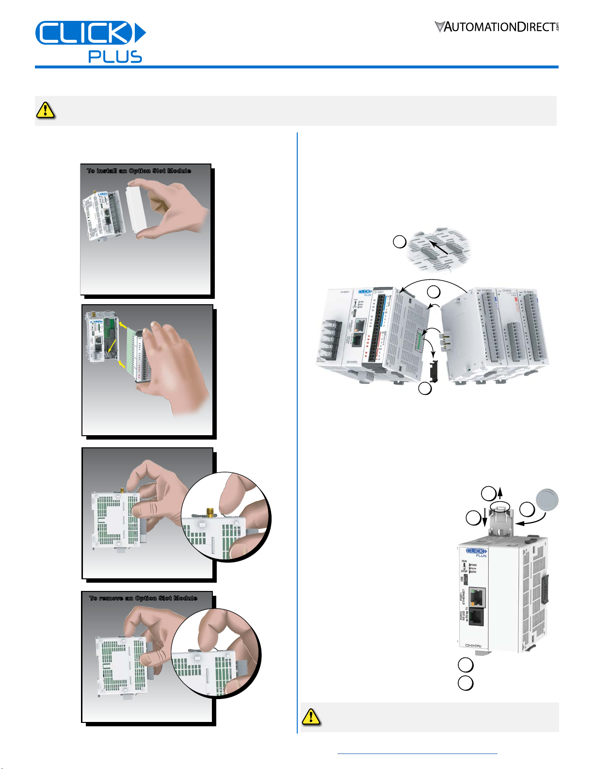
INSTALL OR REMOVE THE OPTION SLOT MODULE INSTALL OR REMOVE STACKABLE MODULES
1. Slide the expansion port LOCK lever to “UNLOCK” and
remove bus cover.
2. Align I/O module with right hand side of CPU, engaging bus
connector so that modules are flush.
3. Slide the “LOCK” lever firmly towards rear of modules, locking
them together.
1
2
3
To remove a module, work the installation steps in reverse.
INSTALL OR REPLACE THE BATTERY
(Lithium CR2032 battery, Part # D0-MC-BAT, not included)
1. Power up the CPU for at least 10 minutes to charge the CPU’s
capacitor prior to removing the
battery. This will retain function
memories. We recommend you
backup data memory before
replacing the battery.
2. Power off the CPU.
3. Pull out the battery holder. (This
may require a small screwdriver to
push in the tab and lift it when the
unit is mounted.)
4. Put in a new battery, with the
positive (+) polarity side facing the
battery holder.
5. Insert the battery holder into the
CPU and push it all the way in.
6. Power on the CPU.
Battery life is about 3 years. Replace
battery within 10 minutes of power off.
Hardware Installation, continued
1 Remove the Option Slot Cover (#C2-FILL)
if it was installed in the CPU, by grasping its
top and bottom front corners, squeezing and
pulling it forward.
2 Hold the
Option Slot
Module by the
top and bottom front
corners, align the PCB card
edge with the guide slots in the
CPU, and slide the module into
its slot. Press the module into place until it is
fully seated
3 Push the top and bottom locking clips
backward until they click into place.
Lift slightly on the locking clips until they
release, then slide each clip forward.
Reverse the procedure.
To install an Option Slot ModuleTo install an Option Slot Module
To remove an Option Slot Module
To remove an Option Slot Module
CAUTION
Cut off all phases of the power source externally and wait 5 seconds before installing or removing the Option Slot
module or Stackable I/O of a running system.
1
3
Power 10+ minutes
2Remove Power
4
5
CAUTION
Battery may explode if mistreated.
Do not recharge, disassemble, or dispose of in fire.
5
3505 HUTCHINSON ROAD
CUMMING, GA 30040-5860
1-800-633-0405
C2-01CPU Series Quick Start Guide
www.automationdirect.com/clickplcs
Copyright© 2021, Automationdirect.com Incorporated/All Rights Reserved Worldwide
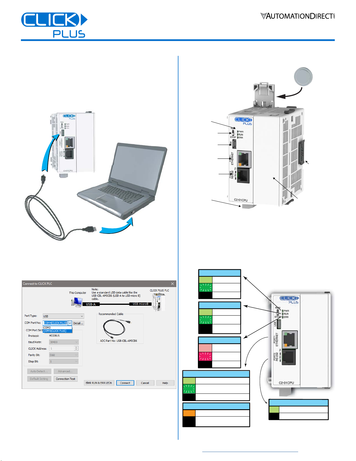
Connecting via USB
To connect the CLICK PLUS CPU to a PC, use a USB A
to USB microB cable, such as the AutomationDirect
USB-CBL-AMICB6 cable.
1. Connect the cable between the CPU microB port and an
available USB port on your PC.
USB Cable
ADC Part #
USB-CBL-AMICB6
PC with
USB A Port
USB
microB
Port
CLICK Plus
PLC
2. Once connected open the Software and select the PLC Menu
and Connect.
3. In the Connect to PLC Window, select USB for Port Type.
4. For Com Port No., select the COMX (CLICK PLUS).
LOAD A PROJECT
The CLICK PLUS CPU is now ready to continue
configuration using the CLICK software and load a project.
External Features
W
tts
micB
pn ot
(fpot)
(10/100)
tt
Pt
R
pnsion
Connto
Pow
Tmin
By
(p)
C2-01CPU(-x)
Blink
LNK/ACT LED (Green)
On Connected to the network
Communicating
Disconnected from the network
Off
100MBIT LED (Orange)
On Communicating at 100Mbps
Communicating at 10Mbps or
disconnected from the network
Off
TX & RX LED (Green)
On Com Port Data Active
No CommunicationOff
ERROR LED (RED)
On Self Diagnostic
Error
Self Diagnostic
Warning
No ErrorOff
Blink
POWER LED (Green)
On Power Good
USB Low
Power Mode
Power Failure
Off
Blink
RUN LED (Green)
On CPU Run Mode
Initializing
Modules
CPU Program
Mode
Off
Blink
LED Status Indicators
6
3505 HUTCHINSON ROAD
CUMMING, GA 30040-5860
1-800-633-0405
C2-01CPU Series Quick Start Guide
www.automationdirect.com/clickplcs
Copyright© 2021, Automationdirect.com Incorporated/All Rights Reserved Worldwide
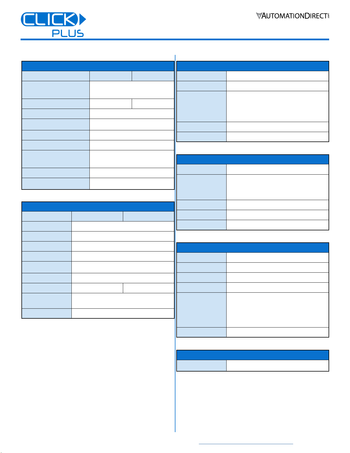
Technical Specifications
Power Specifications
C2-01CPU C2-01CPU-2
Power Input Voltage Range
20–28 VDC Class 2
or SELV(Safety Extra-Low Voltage)
or Limited Energy Circuit power supply
Maximum Power Consumption
20W 22W
Maximum Inrush Current
30A @ 1ms
Acceptable External Power Drop
Max 10ms (AC Power Failure with
C0-00AC or C0-01AC)
Wire Range
16–28 AWG
Wire Strip Length
7.0 mm
Wire Specication
Lead-free, heat resistant,
polyvinyl chloride insulated copper wire,
rated over 80°C
Screw Torque
2.0–2.2 lb-in [0.22–0.25 N·m]
24VDC Power Terminal Block
Replacement
AutomationDirect p/n C0-4TB
General Specifications
C2-01CPU C2-01CPU-2
Operating Temperature
32°F to 131°F [0°C to 55°C]
Storage Temperature
–4°F to 158°F [–20°C to 70°C]
Ambient Humidity
30% to 95% relative humidity (non–condensing)
Altitude
Up to 2,000m
Environmental Air
No corrosive gases
Pollution Degree 2 (UL840)
Environment
For Indoor Use Only
Weight
99g [3.5 oz] 114g [4.0 oz]
Agency Approvals
UL61010 (File No. E157382, E316037);
CE (EN61131-2);
CUL Canadian C22.2
Other
RoHS 2011/65/EU Amendment (EU)2015/863
USB Programming Port Specifications
Communications Ratings
USB 2.0 Full Speed (12Mbps)
Connector
MicroB USB
Bus Power
USB Low power Mode: Max. 500mA USB power
supplied when USB cable is connected.
Disabled Functions:
Stackable I/O BUS
RUN Mode
Recommended Cable
AutomationDirect p/n USB-CBL-AMICB6
USB Cable Length
Max 15 ft.
Ethernet Port Specifications
Communications Ratings
10/100 Base-T
Cable Specications
Category 5
Auto MDI/MDI-X
Yes
Connector
RJ45
Default Settings
IP address assigned by DHCP
àFallback on DHCP failure: 169.254.x.x (APIPA)
Default Fixed Address:
àIP Address: 192.168.0.10
àSubnet Mask: 255.255.0.0
àDefault Gateway: 0.0.0.0
Manually congured Fixed Address
Status Lamp
LINK/ACT, 10/100
Backup Battery Specifications
Type
CR-2032
(AutomationDirect #D0-MC-BAT recommended)
RS-232 Port Specifications
Communications Ratings
RS-232
Port Settings
Baud rate: 2400, 4800, 9600, 19200, 38400,
57600, 115.2k bps
Data bits: 7 bit, 8 bit
Parity: None, Odd, Even
Stop bits: 1 bit, 2 bits
Connector
RJ12 phone jack
Power Supply to HMI
Supply 5V 200mA
Status Lamp
RX, TX
7
3505 HUTCHINSON ROAD
CUMMING, GA 30040-5860
1-800-633-0405
C2-01CPU Series Quick Start Guide
www.automationdirect.com/clickplcs
Copyright© 2021, Automationdirect.com Incorporated/All Rights Reserved Worldwide
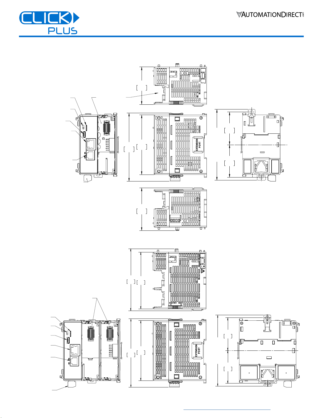
Mechanical Drawings
Unit Dimensions: mm [in]
MODE SWITCH
MICRO USB
ETHERNET 10/100
SERIAL PORT RS-232
STATUS LED's
POWER TERMINAL BLOCK
OPTIONAL
MODULE SLOT
85.0
3.35
97.1
3.82
53.5
2.11
60.8
2.39
46.6
1.83
46.4
1.83
FULLY EXTENDED
( OVERALL )
MODE SWITCH
MICRO USB
STATUS LED's
ETHERNET 10/100
SERIAL PORT RS-232
POWER TERMINAL
BLOCK
EXPANSION SLOTS
85.0
3.35
97.1
3.82
80.5
3.17
87.8
3.46
FULLY EXTENDED
(OVERALL)
46.4
1.83
46.6
1.83
C2-01CPU
C2-01CPU-2

8
3505 HUTCHINSON ROAD
CUMMING, GA 30040-5860
1-800-633-0405
C2-01CPU Series Quick Start Guide
www.automationdirect.com/clickplcs
Copyright© 2021, Automationdirect.com Incorporated/All Rights Reserved Worldwide
Accessories
C2-FILL
Snap-on CPU Option
Slot cover for applications
without an Option Slot
module present.
C0-4TB
Replacement terminal
block for the 24VDC
power connection.
Sold in packs of 2.
D0-MC-BAT
Replacement battery for
CLICK PLUS CPU units.
This manual suits for next models
2
Table of contents
Other AutomationDirect Industrial Equipment manuals


Popular Industrial Equipment manuals by other brands


MyTana
MyTana M844 owner's manual

VERITAS
VERITAS 05P32.03 quick start guide

Valcom
Valcom 1620ES-24VDC Series Operation and maintenance manual

ermengineering
ermengineering AFP-200 Use and maintenance manual

Loveshaw
Loveshaw LITTLE DAVID LD7D/3 Parts and instruction manual

Siemens
Siemens SIRIUS 3RK1105-1AE04-0CA0 Original operating instructions