Movex Zero ATP Pro 5336 Series Installation and operation manual

working in partership with
ENGINEERING MANUAL

2
ENGINEERING MANUAL - ZERO ATP® PRO
APPLICATION CONSIDERATIONS.
The proper selection and application of Movex® products and components, including the related area of product safety, is the responsibility of the
customer. Operating and performance requirements and potential associated issues will vary appreciably depending upon the use and application
of such products and components. The scope of the technical and application information included in this publication is necessarily limited. Unu-
sual operating environments and conditions, lubrication requirements, loading supports, and other factors can materially aect the application
and operating results of the products and components and the customer should carefully review its requirements. Users of our products should
make their own tests to determine the suitability of any product for their particular purposes.
Any technical advice or review furnished by Movex® with respect to the use of products and components is given in good faith and without charge,
and Movex® assumes no obligation or liability for the advice given, or results obtained, all such advice and review being given and accepted at
customer’s risk.
For a copy of our Standard Terms and Conditions of Sale, Disclaimers of Warranty, Limitation of Liability and Remedy, please see our web site
www.movexii.com or contact our Customer Service.
These terms and conditions of sale, disclaimers and limitations of liability apply to any person who may buy, acquire, or use any Movex® product
referred to herein, including any person who buys from a licensed distributor of these branded products.
The applicable Movex® product catalogs and installation/maintenance bulletins must be used only by qualified individuals familiar with Movex®
products; these documents contain important precautions and other information intended to reduce the risk of bodily injury. Refer to these do-
cuments before specifying, installing, operating, or servicing equipment.
Incorrect and/or incomplete data could cause the selection of improper components, potentially resulting in bodily injury. Movex® makes no war-
ranties, express or implied, of merchantability or fitness for a particular purpose.
Movex® will not be liable for direct or indirect incidental, consequential, or punitive damages arising from the use or inability to use this any
of the information made available, including but not limited to product literature, selection programs, and interchange guides. Movex® reserves
the right to correct, modify, update and/or enhance these documents at any time without notice or penalty, including but not limited to pricing,
technical data, etc. Most updated documents can always be found on the website. For more technical information, contact our Technical Support.
© Copyright Movex S.p.A. 2022
The contents of this manual are the copyright of the publisher and may not be reproduced (even extracts) unless permission is granted.
Every care has been taken to ensure the accuracy of the information contained in this publication, but no liability can be accepted for any error
or omission. Catalogue N° M999584

3
ENGINEERING MANUAL - ZERO ATP® PRO
Zero ATP® PRO |Table of contents
INTRODUCTION ....................................................................................................................................................................................................................... 05
VERSIONS .................................................................................................................................................................................................................................... 06
SPEED CALCULATION
Mini motor version (standard) ........................................................................................................................................................................... 08
External motor version (power) ........................................................................................................................................................................ 09
Keyed shaft version .................................................................................................................................................................................................... 10
INSTALLATION ............................................................................................................................................................................................................................ 11
GENERAL TABLE WITH NOSEBARS / ROLLERS ............................................... ................................................................................................. 13
TRANSFER LENGTH WITH NOSEBARS / ROLLERS
520 FT with NoseBars Ø19 ................................................................................................................................................................................... 14
520 LBP with NoseBars Ø19 ................................................................................................................................................................................. 15
520 PRO LBP with NoseBars Ø19 ..................................................................................................................................................................... 16
525 FT with NoseBars Ø19 ..................................................................................................................................................................................... 17
530 PRO LBP with NoseBars Ø19 ..................................................................................................................................................................... 18
550 FT with Rollers Ø40 .......................................................................................................................................................................................... 19
551 FT with Rollers Ø40 .......................................................................................................................................................................................... 20
551 LBP with Rollers Ø40 ...................................................................................................................................................................................... 21
551 PRO LBP with Rollers Ø40 ........................................................................................................................................................................... 22
553 FLEXTOP with Rollers Ø50 .......................................................................................................................................................................... 23
556 FT with Rollers Ø50 ........................................................................................................................................................................................ 24
600 FT with Rollers Ø60 ........................................................................................................................................................................................ 25
GENERAL TABLE WITH SPROCKETS ................................................................................................................................................................. 26
TRANSFER LENGTH WITH SPROCKETS
520 FT with Sprockets .............................................................................................................................................................................................. 28
520 LBP with Sprockets ........................................................................................................................................................................................... 29
520 PRO LBP with Sprockets ............................................................................................................................................................................... 30
525 FT with Sprockets ............................................................................................................................................................................................... 31
530 PRO LBP with Sprockets ............................................................................................................................................................................... 32
550 FT with Sprockets ............................................................................................................................................................................................... 33
551 FT with Sprockets ................................................................................................................................................................................................ 34
551 LBP with Sprockets ............................................................................................................................................................................................ 35
551 PRO LBP with Sprockets ................................................................................................................................................................................ 36
553 FLEXTOP with Sprockets ............................................................................................................................................................................... 37
556 FT with Sprockets ............................................................................................................................................................................................... 38
600 FT with Sprockets .............................................................................................................................................................................................. 39
820 FT with Sprockets ............................................................................................................................................................................................... 40
821 LBP with Sprockets ......................................................................................................................................................................................... 41

4
ENGINEERING MANUAL - ZERO ATP® PRO
INSTALLATION WITH EXTERNAL TRANSMISSION ........................................................................................................................................ 42
PERSONAL PROTECTIVE EQUIPMENT .................................................................................................................................................................... 43
DO’S AND DON’TS ................................................................................................................................................................................................................ 44
MAINTENANCE
General maintenance instructions ............................................................................................................................................................. 45
Installation on the line ........................................................................................................................................................................................... 46
Inspection .......................................................................................................................................................................................................................... 47
CLEANING .................................................................................................................................................................................................................................... 48
TROUBLESHOOTING ........................................................................................................................................................................................................... 49
MATERIAL
LFA - LFB ............................................................................................................................................................................................................................. 50
MX ............................................................................................................................................................................................................................................ 51
FREQUENTLY ASKED QUESTION ................................................................................................................................................................................ 52
Zero ATP® PRO |Table of contents

5
ENGINEERING MANUAL - ZERO ATP® PRO
Zero ATP® PRO |Introduction
Mini-motor or
keyed shaft
Z16 drive sprockets
with incorporate key
Chrome steel
bearings
Compact
design
Smallest possible
transfer
ENSAT
M8 Side frame
AISI 304
Side frame
AISI 304
General products features Plug and play solution
• Self-tensioning
• Maintenance free
• Compact design
• Low voltage
• Easy installation
• Easy integration
Simultaneous transport of:
HIGH LOAD & BIG GOODSLIGHTWEIGHT & SMALL GOODS
CONVEYOR
A
CONVEYOR
B
CONVEYOR
A
CONVEYOR
B
Belt series 510 FT
Belt width 6inch ÷ 24inch
Transfer length 80 or 150 mm
Transmission Mini motor or Keyed shaft
Material LFA, MX or LFB
Max working load 3000 N/m
User-friendliness
Easy installation and interchangeability.
Minimized maintenance
Zero ATPTM Pro doesn’t require maintenance.
Short transfer connection
It works perfectly with small products.
Unique design
It solves traditional transfer plate issues.
Safer design
Minimized the possibility of injuries.
Saving (Energy, resources, time)
Fewer resources and time employed.
P
A
T
E
N
T
E
D
6
ENGINEERING MANUAL - ZERO ATP® PRO
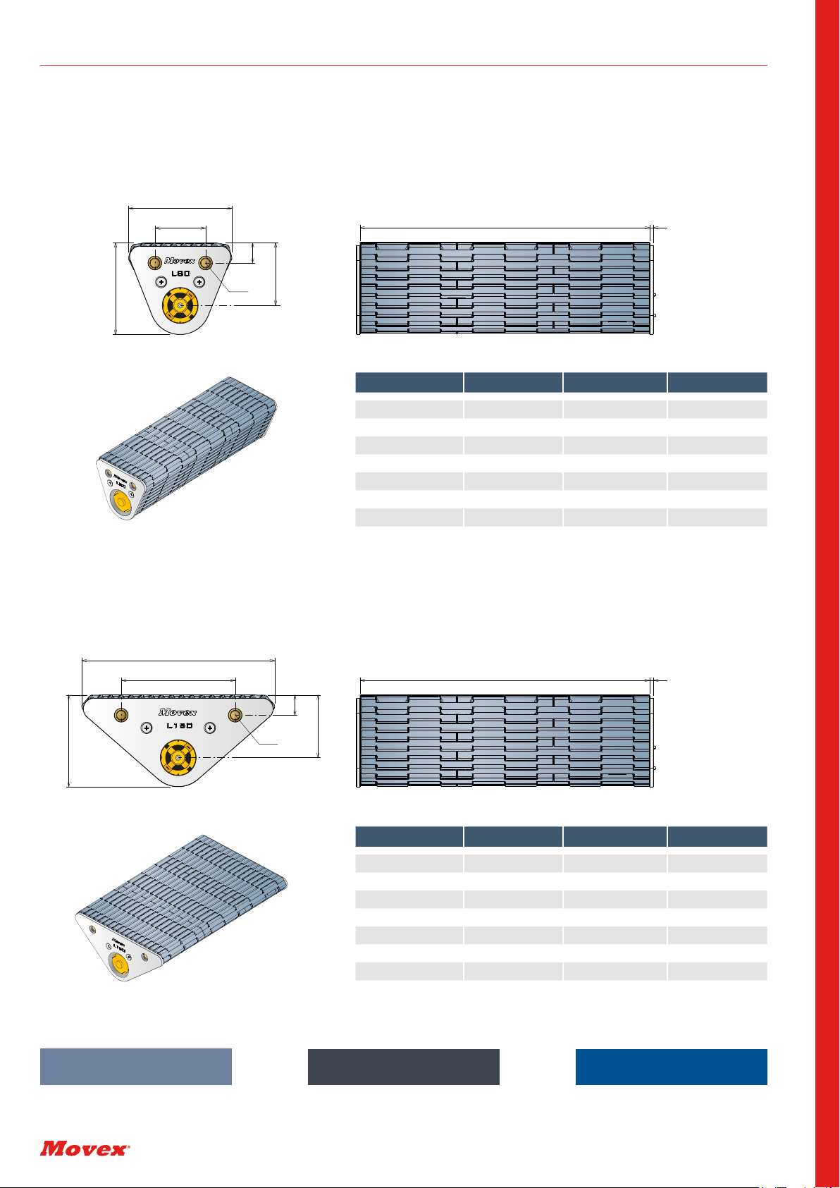
VERSION A - WITH MINI MOTOR
Zero ATP® PRO |Versions
Length 80 mm
49.5
90
150
40
80
16
49.5
16
Width 3
Width 3
M8
M8
72.5
72.5
Series *Material Width Version
5336 * 0006 A
5336 * 0009 A
5336 * 0012 A
5336 * 0015 A
5336 * 0018 A
5336 * 0021 A
5336 * 0024 A
Length 150 mm
Series *Material Width Version
5338 * 0006 A
5338 * 0009 A
5338 * 0012 A
5338 * 0015 A
5338 * 0018 A
5338 * 0021 A
5338 * 0024 A
LFA | Low friction Acetal LFB | Low friction Acetal
Material information, page 50
MX | Performance PBT
Material information, page 51 Material information, page 50
*Wider version on request
49.5
90
150
40
80
16
49.5
16
Width 3
Width 3
M8
M8
72.5
72.5
*Wider version on request
49.5
90
150
40
80
16
49.5
16
Width 3
Width 3
M8
M8
72.5
72.5
49.5
90
150
40
80
16
49.5
16
Width 3
Width 3
M8
M8
72.5
72.5

7
ENGINEERING MANUAL - ZERO ATP® PRO
VERSION B - WITH KEYED SHAFT
Length 80 mm
49.5
90
150
40
80
16
49.5
16
Width 3
M8
M8
Width 3
75
60
Keyseat
5x5
Ø15
75
60
Keyseat
5x5
Ø15
72.5
72.5
Series *Material Width Version
5336 * 0006 B
5336 * 0009 B
5336 * 0012 B
5336 * 0015 B
5336 * 0018 B
5336 * 0021 B
5336 * 0024 B
Length 150 mm
Series *Material Width Version
5338 * 0006 B
5338 * 0009 B
5338 * 0012 B
5338 * 0015 B
5338 * 0018 B
5338 * 0021 B
5338 * 0024 B
*Wider version on request
Zero ATP® PRO |Versions
LFA | Low friction Acetal LFB | Low friction Acetal
Material information, page 49
MX | Performance PBT
Material information, page 50 Material information, page 49
49.5
90
150
40
80
16
49.5
16
Width 3
M8
M8
Width 3
75
60
Keyseat
5x5
Ø15
75
60
Keyseat
5x5
Ø15
72.5
72.5
49.5
90
150
40
80
16
49.5
16
Width 3
M8
M8
Width 3
75
60
Keyseat
5x5
Ø15
75
60
Keyseat
5x5
Ø15
72.5
72.5
49.5
90
150
40
80
16
49.5
16
Width 3
M8
M8
Width 3
75
60
Keyseat
5x5
Ø15
75
60
Keyseat
5x5
Ø15
72.5
72.5
*Wider version on request

8
ENGINEERING MANUAL - ZERO ATP® PRO
Zero ATP® PRO |Speed calculation
MINI MOTOR VERSION (STANDARD)
Voltage
m/min
RPM
0
40 60
080 100 120
2
44.5
6
8
10
12
14
16
20
15
8.6
12.9
4,4 m/min
(min speed)
14,7 m/min
(max speed)
Zero ATP® PRO version A is provided with the mini motor installed internally; this will make the Zero ATP® PRO
compact and easy to be installed into new or exiting lines.
Operating relative humidity 20% - 85%
Operating temperature range -10°C - +60°C
Optional cover for
motor connection
Article-Nr. 300601
Technical specifications
Output Speed 84 rpm
Supply Voltage 6 - 15 V dc
Maximum Output torque 6539 g.cm
DC Motor type Brushed
Shaft Diameter 6 mm
Power Rating 7.85 W
Gearhead Type Planetry
Length 73.9 mm
Width 32 (Dia.) mm
Current rating 990 mA
Weight 211g
NOTE: Motor speeds may vary by (+) or (-) 12.5% RPM - Revolutions per minute m/min - Meters per minute
m/min
0
10 15
020 25 30 35 40 45 50 55
10
20
30
40
50
60
70
5
db(A)
m/min
0
015
5 10
10
20
30
40
50
60
70
db(A)
Zero ATP® PRO noise level
The graphic on the right shows the noise
level of a 9-inch Zero ATP® PRO at dierent
speeds with the following conditions: 1m
distance, 1m height, 23°C room temperature.

9
ENGINEERING MANUAL - ZERO ATP® PRO
Zero ATP® PRO |Speed Calculation
EXTERNAL MOTOR VERSION (POWER)
m/min
RPM
100 150
0200 250 300 350 400
50
0
10
20
30
40
50
60
4,5
15
8,5
10,9
Voltage
16,4 m/min
(min speed)
54,5 m/min
(max speed)
In case standard internal motor doesn’t let your line achieving required speed, more powerful versions can be used.
Because of the small dimension of the Zero ATP® PRO, a dierent motor than the standard must be fixed externally,
by using a plate or directly at the conveyor frame.
The following motor is just an example of motors that can be used, able to achieve 55 m/min.
Also dierent/traditional motor scan be used by making the required adapter.
Operating relative humidity 20% - 85%
Operating temperature range -10°C - +60°C
Technical specifications
NOTE: Motor speeds may vary by (+) or (-) 12.5% RPM - Revolutions per minute m/min - Meters per minute
Output Speed 309 rpm
Supply Voltage 4.5 - 15 V dc
Maximum Output torque 3000 g.cm
DC Motor type Brushed
Shaft Diameter 6 mm
Power Rating 19.8 W
Gearhead Type Spur
Length 82.5 mm
Width 39.3 mm
Current rating 2810 mA
Weight 285 g
m/min
0
10 15
020 25 30 35 40 45 50 55
10
20
30
40
50
60
70
5
db(A)
m/min
0
015
5 10
10
20
30
40
50
60
70
db(A)
Zero ATP® PRO noise level
The graphic on the right shows the noise
level of a 9-inch Zero ATP® PRO at dierent
speeds with the following conditions: 1m
distance, 1m height, 23°C room temperature.

10
ENGINEERING MANUAL - ZERO ATP® PRO
Zero ATP® PRO |Speed calculation
KEYED SHAFT VERSION
Zero ATP® PRO version B is provided with keyed shaft, which can be connected by using a custom motor with an
adapter or with an external roller chain transmission.
By using this graphic, you can easily calculate
revolutions per minute based on the required speed.
Based on the selected transmission sprockets, speed
may vary more or less than established values.
0
100 1500 200 250 300 350 400
10
20
30
40
50
60
70
m/min
RPM
50 450 500
RPM - Revolutions per minute
m/min - Meters per minute
For more information about installation, please check page 42
Output speed can be easily calculated by using the pitch diameter of the
sprocket, d.45mm.
45
45
150
80
45
45
150
80
Keyed shaft version
Includes a 15 mm shaft
with standard key seat 5x5
for roller chain transmission.
Keyseat
5x5
Ø15
In case of a connection with roller chain
transmission, it is suggested to connect
the Zero ATP® PRO to the previous conveyor
(drive side) for a better stability.
DRIVE SIDEIDLER SIDE

11
ENGINEERING MANUAL - ZERO ATP® PRO
Zero ATP® PRO |Installation
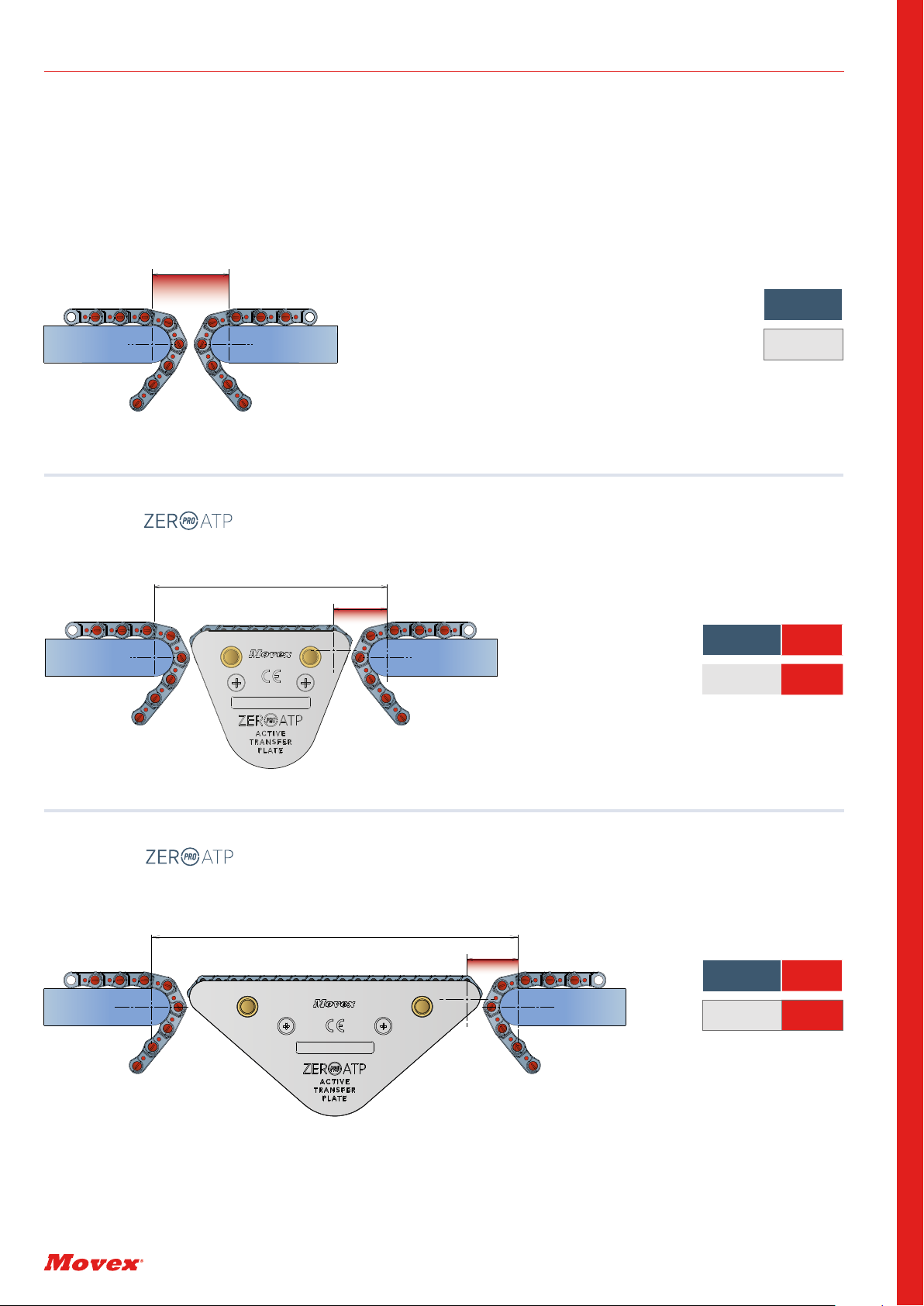
Ideal transfer for relative heavy products. The Zero ATP® PRO results in line with the infeed and outfeed belts.
The product is supported from the three belts and will leave the Zero ATP® PRO in a smooth way.
TRANSFER - ALIGNED
TRANSFER - LOWER
TRANSFER - UP & DOWN
Ideal transfer for relative light products. The Zero ATP® PRO results lower than infeed and outfeed belts. The product will
fall from the first belt and climb to the second belt. This transfer is ideal to give more grip to the product.
Ideal transfer when the product results particularly small and light. The Zero ATP® PRO results lower than the infe-
ed belt and higher than the outfeed belt but it’s installed slightly inclined. The product will fall from the first belt to
the second belt while climbing on the Zero ATP® PRO. This transfer is ideal to avoid gaps on the outfeed, especially
when used with Zero ATP® PRO 80.

12
ENGINEERING MANUAL - ZERO ATP® PRO
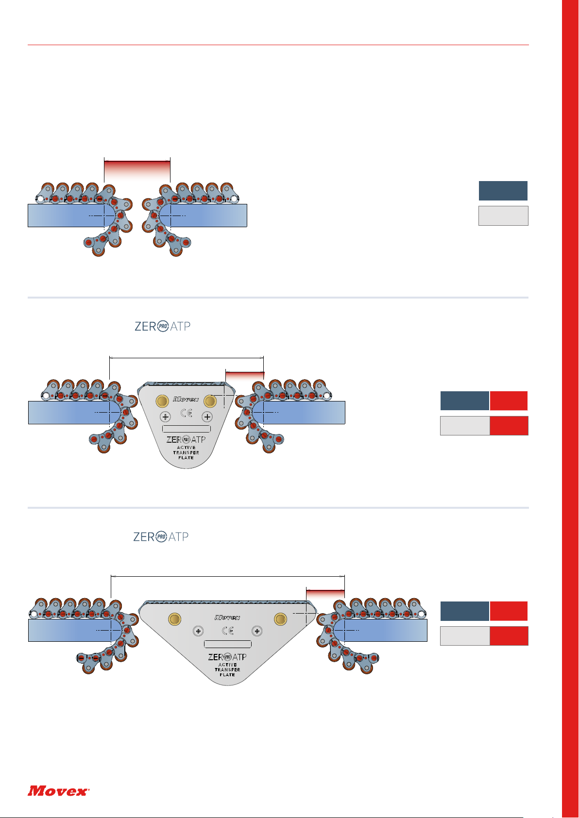
Special transfer head to side usually developed with FTT belts can be now created with Zero ATP® PRO.
Products will have to be launched on the outfeed.
TRANSFER - PACKFALL
TRANSFER - INCLINED/DECLINED
Zero ATP® PRO |Installation
TRANSFER - HEAD TO SIDE
Ideal transfer when there is a mix of small and big products. . The Zero ATP® PRO results lower than the infeed belt
and higher than the outfeed belt and it’s installed completely straight. The product will fall from the first belt to the
Zero ATP® PRO and from the Zero ATP® PRO to the second belt.
Ideal transfer to connect a straight infeed belt and an inclined outfeed belt. The Zero ATP® PRO is following the inclination
of the outfeed belt. Attention: if the coecient of friction is too low, the product may slide back, in this case it is requied
to reduce the inclination of the Zero ATP® PRO.

13
ENGINEERING MANUAL - ZERO ATP® PRO
Zero ATP® PRO |General table with NoseBars / Rollers
TABLE TRANSFER LENGTH WITH NOSEBARS / ROLLERS
MODULAR BELTS UoM TRADITIONAL
510 FT (mm) 22,0 22,0 22,0
520 FT
520 HD FT
520 FG
520 M
521 FT
522 HD FT
(mm) 40,0 27,5 26,5
525 HD FT
525 HD FG
530 FT (mm) 40,0 29,0 28,5
520 GT (mm) 44,0 31,5 30,5
525 HD GT (mm) 44,0 33,0 32,5
530 GT (mm) 44,0 33,0 32,5
530 LBP (mm) 44,0 30,0 30,0
530 PRO LBP (mm) 44,0 30,0 30,0
520 PRO LBP (mm) 55,0 33,0 33,0
520 LBP (mm) 61,0 34,0 35,0
550 FT
550 FG
550 PRO FT
550 PRO M
(mm) 63,5 36,5 36,0
550 GT (mm) 67,5 40,5 40,0
551 FT (mm) 71,0 39,0 39,0
551 GT (mm) 75,0 43,0 43,0
553 FLEX TOP (mm) 74,5 41,0 41,0
551 PRO LBP (mm) 81,0 42,0 41,0
556 FT (mm) 82,0 43,0 42,0
556 GT (mm) 86,0 47,0 46,0
600 FT (mm) 90,5 46,0 44,0
551 LBP (mm) 94,0 46,0 43,0
Type of transfer
LT
LT= Transfer length between
Zero ATP® PRO 150 and NoseBars.
LT= Transfer length between
Zero ATP® PRO 80 and NoseBars.
LT
LT= Transfer length
between NoseBars.
LT
80 150
14
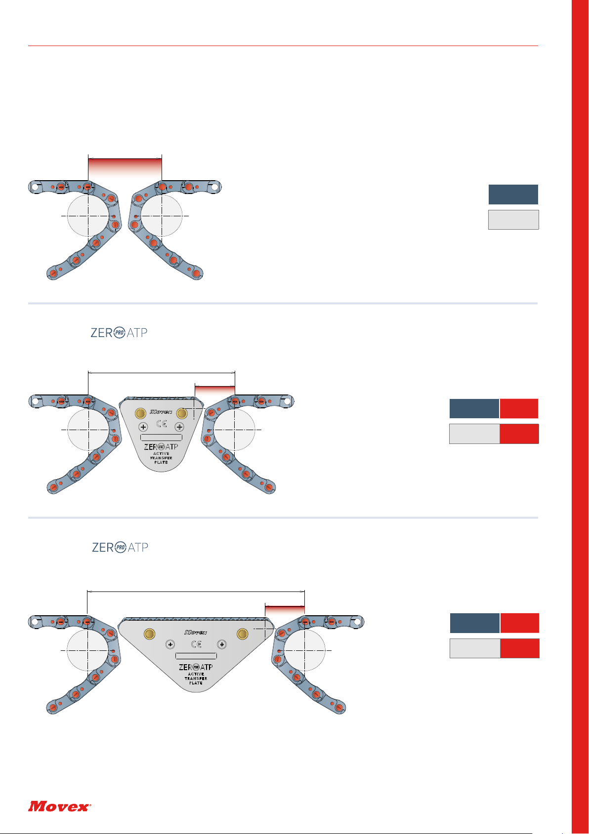
ENGINEERING MANUAL - ZERO ATP® PRO
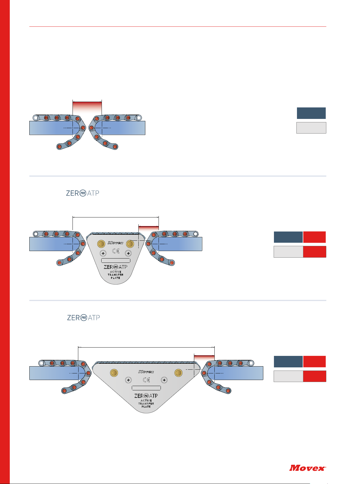
520 FT - - 520 FT
Zero ATP® PRO |520 FT - with NoseBars Ø19
520 FT -520 FT
520 FT - - 520 FT
LT Δ%:
26,5 mm - 34%
LT Δ%:
27,5 mm - 31%
LT
40,0 mm
Valid also for: 520 HD FT; 520 FTT; 520 FG; 520 M; 521 FT, 522 HD FT.
40
118
27,5
190
26,5
LT: Transfer length center to center (see page 12)
Δ%:Refers to the comparison between transfer with NoseBars and transfer with Zero ATP® PRO.
150
80

15
ENGINEERING MANUAL - ZERO ATP® PRO
Zero ATP® PRO |520 LBP- with NoseBars Ø19
520 LBP -520 LBP
520 LBP - - 520 LBP
520 LBP - - 520 LBP
LT: Transfer length center to center (see page 12)
Δ%:Refers to the comparison between transfer with NoseBars and transfer with Zero ATP® PRO.
LT Δ%:
35,0 mm - 43%
LT Δ%:
34,0 mm - 44%
LT
61,0 mm
61
203
35
132,5
34
150
80
16
ENGINEERING MANUAL - ZERO ATP® PRO
Zero ATP® PRO |520 PRO LBP- with NoseBars Ø19
520 PRO LBP -520 PRO LBP
520 PRO LBP - - 520 PRO LBP
520 PRO LBP - - 520 PRO LBP
LT: Transfer length center to center (see page 12)
Δ%:Refers to the comparison between transfer with NoseBars and transfer with Zero ATP® PRO.
LT Δ%:
33,0 mm - 40%
LT Δ%:
33,0 mm - 40%
LT
55,0 mm
55
129
33
199
33
150
80
17
ENGINEERING MANUAL - ZERO ATP® PRO
Zero ATP® PRO |525 FT - with NoseBars Ø19
525 FT -525 FT
525 FT --525 FT
525 FT --525 FT
LT Δ%:
28,5 mm - 29%
LT Δ%:
29,0 mm - 28%
LT
40,0 mm
Valid also for: 525 FTT; 525 FG; 530 FT; 530 FTT.
119,5
29
40
190
28,5
LT: Transfer length center to center (see page 12)
Δ%:Refers to the comparison between transfer with NoseBars and transfer with Zero ATP® PRO.
150
80

18
ENGINEERING MANUAL - ZERO ATP® PRO
Zero ATP® PRO |530 PRO LBP - with NoseBars Ø19
530 PRO LBP -530 PRO LBP
530 PRO LBP --530 PRO LBP
530 PRO LBP --530 PRO LBP
LT Δ%:
30,0 mm - 32%
LT Δ%:
30,0 mm - 32%
LT
44,0 mm
Valid also for: 530 LBP.
44
122
30
192,5
30
LT: Transfer length center to center (see page 12)
Δ%:Refers to the comparison between transfer with NoseBars and transfer with Zero ATP® PRO.
150
80

19
ENGINEERING MANUAL - ZERO ATP® PRO
Zero ATP® PRO |550 FT - with Rollers Ø40
550 FT -550 FT
550 FT --550 FT
550 FT --550 FT
LT Δ%:
36,0 mm - 43%
LT Δ%:
36,5 mm - 42%
LT
63,5 mm
Valid also for: 550 FTT; 550 FG; 550 PRO FT; 550 PRO M.
136
36,5
63,5
206
36
LT: Transfer length center to center (see page 12)
Δ%:Refers to the comparison between transfer with NoseBars and transfer with Zero ATP® PRO.
150
80
20
ENGINEERING MANUAL - ZERO ATP® PRO
Zero ATP® PRO |551 FT - with Rollers Ø40
551 FT -551 FT
551 FT --551 FT
551 FT --551 FT
LT Δ%:
39,0 mm - 45%
LT Δ%:
39,0 mm - 45%
LT
71,0 mm
Valid also for: 551 FTT.
39
210
141
39
71
LT: Transfer length center to center (see page 12)
Δ%:Refers to the comparison between transfer with NoseBars and transfer with Zero ATP® PRO.
150
80
Table of contents
Other Movex Industrial Equipment manuals


Popular Industrial Equipment manuals by other brands

Graco
Graco 255703 Instructions and parts

Siemens
Siemens SIPLUS HCS4200 PROFINET Compact operating instructions

Elsamec
Elsamec UNIKO-1M EVOLUTION Series quick start guide

Aventics
Aventics TRB Series Repair instructions

Shaver
Shaver HD-10 Operator's manual

XYZ Machine Tools
XYZ Machine Tools ProTURN SLX 1630 Safety, installation, maintenance, service & parts list manual

BLOCK AND ROLL
BLOCK AND ROLL Multi Form 700 instruction manual

NIKA
NIKA NL-UHV / DX3 Operation manual

Aventics
Aventics EBS-ET-VE Series operating instructions

jost
jost JSK 39 Installation and Operating Instrucitons

Swegon
Swegon CASA W03CMB Installation instruction

Vega
Vega VEGAMET 308 Technical information & operating instructions


