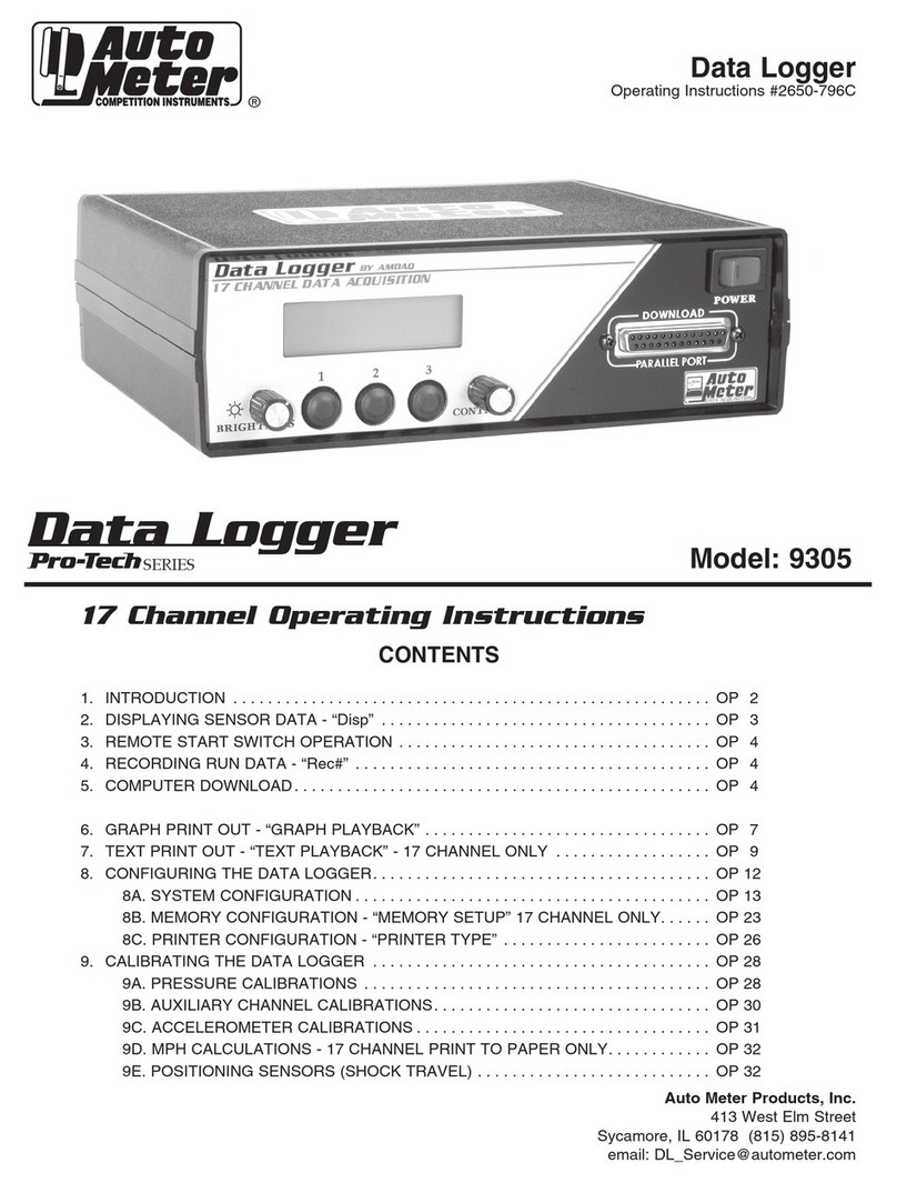
AutoMeter Pro-Tech Series User manual

Data Logger
34 Channel Operating Instructions
Auto Meter Products, Inc.
413 West Elm Street
Sycamore, IL 60178 (815) 895-8141
email: [email protected]
Data Logger
Operating Instructions #2650-627
®
Model: 9301
CONTENTS
1. INTRODUCTION ....................................................... OP 2
2. DISPLAYING SENSOR DATA - “Disp” . . . . . . . . . . . . . . . . . . . . . . . . . . . . . . . . . . . . . . OP 3
3. REMOTE START SWITCH OPERATION . . . . . . . . . . . . . . . . . . . . . . . . . . . . . . . . . . . . OP 4
4. RECORDINGRUNDATA-“Rec#” ......................................... OP 4
5. COMPUTERDOWNLOAD................................................ OP 5
6. CONFIGURINGTHEDATALOGGER....................................... OP 6
6A.SYSTEMCONFIGURATION......................................... OP 6
7. CALIBRATINGTHEDATALOGGER ....................................... OP 7
7A.PRESSURECALIBRATIONS ........................................ OP 7
7B. AUXILIARY CHANNEL CALIBRATIONS. . . . . . . . . . . . . . . . . . . . . . . . . . . . . . . . OP 9
7C. ACCELEROMETER CALIBRATIONS . . . . . . . . . . . . . . . . . . . . . . . . . . . . . . . . . . OP 10
7D. POSITIONING SENSORS (SHOCK TRAVEL) . . . . . . . . . . . . . . . . . . . . . . . . . . . OP 11
8. CALIBRATING AUX CHANNELS 5-20 . . . . . . . . . . . . . . . . . . . . . . . . . . . . . . . . . . . . . . OP 16
SERIES

1. INTRODUCTION
This manual explains how to operate the Data Logger. We have made the Data Logger as easy to use as possible.
The 34 channel computer is operated much the same as the 17 channel computer.
DISPALYING SENSOR DATA
Same as 17 channel, except pressing button #2 toggles through AUX 1-20. AUX 1-4 will be displayed in engineering
units, while AUX 5-20 will only display ADC numbers. You can still view AUX 5-20 to verify they are working, but you
will
be unable to read actual channel units until the recorded run is downloaded to the PC and calibrated.
MEMORY - RUN 1, RUN 2
The 34 channel computer has two runs available for recording. Run 1 and Run 2. The button on the front panel of the
data logger indicates which run is being used. If the switch is set to Run 1, each time a recording is started, the data is
recorded into the RUN 1 memory, and when a download is performed, RUN 1 is transferred to the PC.
To recoed RUN 2, simply press the button on the front panel once and it will toggle to RUN 2 for recording
and download.
COMPUTER DOWNLOAD
See page OP 5.
AUTO-DOWNLOAD
Display on Data Logger Brief Details
Press No
Press Enter
Press “Up” Once
Press Up
Press Enter
Press Yes
Press No
Press DNLD
Download will start at 0
Start from beginning of Memory.
Will display download End Time.
To desired Download End Time.
Identifies Download Time Bracket.
Store Settings.
No settings will be stored.
Sends data to computer.
3.
4.
5.
6.
7.
8.
9.
To Download from the Launch to the End of the RunTo Download from the Launch to the End of the Run
FIND LAUNCH
Start at Sec. 0
Stop at Sec. None
Stop at Sec. “X”
Stop at Sec. “Y”
Update Auto DL?
Playback Type
Display on Data Logger Brief Details
CHOOSE MODE Press Play Finds stored settings and sends data to computer.
10.
Set Up One Button DownloadSet Up One Button Download
One Button Download
To enable one button download, the computer must be ready to accept data and cables connected at both ends. (Download box must
be ser 0n “Receive” and be connected to Data Logger.
If you use the Data Logger to find the start of the race, and you know that your car consistently runs 8.90’s, you can set the Stop at Sec.
window to remove any extra time at the end of the run. This will drastically speed up the download process.
If you use the Data Logger to find the start of the race, and you know that your car consistently runs 8.90’s, you can set the Stop at Sec.
window to remove any extra time at the end of the run. This will drastically speed up the download process.
OP 2OP 2

CHOOSE MODE
Disp Rec# Play
1 2 3
Function
Choices Buttons
Display Brief
The following pages have diagrams and details to get you started. Don’t worry about accidentally pressing the wrong button
and loosing data or your calibrations. Any configuration or calibration can easily be re-entered, and data has to be manually
removed. If you find yourself lost in an operation, just turn the unit OFF and ON to reset to the main menu (“CHOOSE MODE”).
When an option is explained in this manual, you will only be told to press the buttons relating to the option. If other options are
available on the same screen, they will not be explained. For more details on those options, see the related section.
We hope you enjoy your Data Logger and hope it proves to be an asset to your racing program.
CALIBRATING AUX 1-4
Calibrated the same as the 17 channel computer.
CALIBRATING AUX 5-20
The calibration numbers for these channels are calibrated in the Data Facts Pro 34 Channel Software.
(See Software Channel Maintenance Section Page 23)
The LCD display on the front of the Data Logger guides you through the functions. It identifies the function on the top line, and up
to three choices on the bottom line. A function/option can be selected by pressing the button directly below the name.
To operate the system, select a function by pressing one of the three buttons, and following the menus to the task of your choice.
OP 3

2. DISPLAYING SENSOR DATA - “Disp”
Display (“Disp”) mode is selected from the “CHOOSE MODE” screen and allows you to display active sensor data. Use the three
buttons below the screen to select the data to be viewed. Display enables view of Engine and Driveshaft RPM, Accelerometer,
Pressure, EGT and Aux 1-4 only.
ER XXXX DR XXXX
XX.XXG XX.XXPSI
CHOOSE MODE
Disp Rec# Play
Press the “Disp” button to enter the “Disp” mode and display
sensor data.
Press “Disp”
Button 2
Display Aux. Channels
Button 3
Display EGT’s
The first screen in the “Disp” mode shows Engine RPM,
Drive shaft RPM, Acceleration and Fuel pressure.
• Pressing button 2 will display the Auxiliary channels
information.
• Pressing button 3 will display the EGT’s.
C1 X.XXX 2 X.XXX
3 X.XXX 4 X.XXX
Button 1
Return to prev. screen
Button 3
Display EGT’s
The Auxiliary channels are displayed as shown.
• Press button 1 to return to previous screen.
• Press button 3 to display the EGT’s.
• Pressing button 2 cycles through Aux 5-20.
TC5 XXXX 6 XXXX
7 XXXX 8 XXXX
Button 1
Return to first “Disp” screen
Button 2
Return to Auxiliary
channel display
Button 3
Alternate between Aux.
Channels 1-4 and 5-8
The EGT’s are displayed as shown.
• Press button 1 to return to the first screen in the “Disp” mode
with RPM’s, Acceleration and Fuel pressure.
• Press button 2 to return to the Auxiliary channels display.
• Press button 3 to alternate the display between EGT channels
1-4 and 5-8.
NOTE:
• To exit the “Disp” mode and return to the “CHOOSE MODE”, press and hold buttons 1 and 2 until the unit resets itself.
• The Display mode for AUX 5-20 does not show engineering units.
The number displayed is the ADC number for that channel.
Display Brief Details
1 2 3
1 2 3
1 2 3
1 2 3

OP 5
3. REMOTE START SWITCH OPERATION
The remote switch supplied with the Data Logger is a single throw, momentary switch. Pressing the switch is the same as pressing
the “Rec#” button in the “CHOOSE MODE”. The unit will continue recording until the memory for the run is full.
4. RECORDING RUN DATA - “Rec#”
The Record (“Rec#”) mode, selected from the “CHOOSE MODE”, allows you to begin recording run data.
The memory in the 9301 is split into 2 runs. The square run button on the front panel selects which run will be
recorded and/or downloaded.
CHOOSE MODE
Disp Rec# Play
There are three options to start recording data:
•Press “Rec#”, in the “CHOOSE MODE”.
• Activate the remote start switch
(works like pressing the “Rec#” button).
•Exceeding the configurable preset start engine or drive shaft
RPM value by pressing the “Rec#” button or activate the
remote start switch. If the system is configured for multiple
runs, the number of runs remaining will appear next to Rec.
Pressing and holding the “Rec#” button displays the preset
start engine or drive shaft RPM.
3 options to start recording.
• Press “Rec#” button
• Remote start switch
• Exceeding preset RPM
“EXIT”
Exit to “CHOOSE MODE”
Display Brief Details
1 2 3
ERPM Start XXXX
EXIT
1 2 3
* Optional screen *
This screen will be displayed only if an engine RPM (“START
RPM”) has been configured as the trigger. Data recording will
not begin until the configured RPM value has been exceeded.
Engine RPM will be displayed in place of “XXXX”.
• Press the “EXIT” button to return the “CHOOSE MODE”.
RECORDING DATA
1 2 3
This screen is displayed during recording. The computer
will continue receiving and recording data until the allocated
memory for that run is full.
“END”
Return to the
“CHOOSE MODE”
RECORD COMPLETE
END
1 2 3
Once the “Record” mode has been stopped, the unit will display
record complete.
•Press the “END” button to return to the “CHOOSE MODE”.

This screen selects the start point for the print out. If no run is
recorded the Data Logger returns to the “CHOOSE MODE”.
•Selecting “Yes “ allows the Data Logger to find the point of launch.
Approximately 1 second is subtracted from this point. This enables
1-2 seconds of data to be printed prior to the launch point. While the
unit is calculating the exact launch point “Searching XXX” will be
displayed with an “ABORT” option. “ABORT” will return you to the
main menu.
•Selecting “No” advances to the next screen to allow you to enter the
starting point manually.
OP 6
5. COMPUTER DOWNLOAD
Select which run you want to download with the square run select button on the front panel of the data logger.
9301 download is the same as the 9305.
CHOOSE MODE
Disp Rec# Play
Press the “Play” button to access all playback functions.
Press “Play”
Display Brief Details
1 2 3
Choose Function
Setup Cal Play
Press the “Play” button to enter the Play function.
Press “Play”
1 2 3
Find Launch ?
Yes No
“Yes”
Data Logger finds
point of launch
“No”
Advance to the next screen
and enter selection
1 2 3
Start at Sec. X
Up Down ENTER
The start point of the print out is selected from this screen. If you
chose “YES” on the previous screen, the calculated start point will be
displayed in place of the “X”.
•The “Up” button increases the start time.
•The “Down” button decreases the start time.
•After reaching the correct starting time, press the “ENTER” button
to make your selection. If no time is chosen, data will print from 0
seconds.
“Up”
Increase time
“Down”
Decrease time
“ENTER”
Make selection
1 2 3
Stop at Sec. X
Up Down ENTER
The stop point of the print out is selected from this screen.
•The “Up” button increases the stop time.
•The “Down” button decreases the stop time.
•After reaching the correct stop time, press the “ENTER” button to
make your selection.
“Up”
Increase time
“Down”
Decrease time
“ENTER”
Make selection
1 2 3
Update Auto DL ?
Yes No
Next time a file is downloaded, if the PC is ready to receive the file
and the Download cable is connected to the Data Logger,
pressing Play in the main screen will Download the settings you just
entered.
Select “Yes”
1 2 3
Playback type ?
DNLD GRAPH TEXT Press the “DNLD” button to Download the data to the PC.
Press “DNLD”
1 2 3

OP 7
6. CONFIGURING THE DATA LOGGER
The Data Logger software has several customizable options. These options allow you to tailor the system operation and
playback functions to your individual needs. The entire configuration process can be performed with menu selections on
the LCD screen.
This is a list of options provided by the configuration software. They are explained in more detail in the following
sections.
SYSTEM CONFIGURATION OPTIONS:
1. Data Recording
A) Manual start data recording
B) Delayed start data recording (activated by a selectable engine or drive shaft RPM)
2. Units for auxiliary channels
A) Auxiliary channel 1
B) Auxiliary channel 2
C) Auxiliary channel 3
D) Auxiliary channel 4
6A. SYSTEM CONFIGURATION
The following steps lead you through the System Configuration process.
CHOOSE MODE
Disp Rec# Play
Press the “Play” button. The configuration functions are
accessed through the Play mode.
Press “Play”
Display Brief Details
1 2 3
Choose Function
Setup Cal Play
Press the “Setup” button to enter the System Configuration mode.
Press “Setup”
1 2 3
Print SETUP ?
Yes No
The current configuration can be printed from this screen before
any changes are made. This is always a good idea. It gives
you a copy of your current configuration to return to incase an
error is occurs.
• Connect your printer and select “Yes” to print the file
• Select “No” to go directly to the “CHOOSE FOR SETUP”
screen.
“Yes”
Print current setup
“NO”
Do not print current setup
1 2 3
ER Pls/Rev 4
UP DOWN ENTER
1 2 3
This option allows you to change the number of pulses per
revolution for the Engine RPM channel. Use the up arrow to
change the number then press enter.
The starting device for recording is selected on this screen.
• Pressing the “MAN” button selects a manual start. Both the
“Rec#” button and the remote switch will start recording.
• Pressing the “DRPM” button selects drive shaft RPM as the
starting device. Recording will start when the drive shaft
exceeds 300 RPM. To ensure one second of data is saved
before launch, a second block of data will stored.
• Pressing the “ERPM” button selects engine RPM as the
starting device. Recording will start after a preset engine
RPM has been reached.
RECORD MODE
MAN DRPM ERPM
“MAN”
“Rec#” button or remote
start switch
“DRPM”
Driveshaft RPM
“ERPM”
Engine RPM
1 2 3

Display Brief Details
ENABLE RESTART ?
YES EXIT NO
The “ENABLE RESTART ?” screen allows you to instantly
restart a recording. This is used when the Data Logger is set
in manual start mode and a recording is started accidentally
or to early. If this option is OFF and a recording needs to
be restarted, it takes several steps to cancel and restart the
recording. With this option ON, it only takes the press of a
button. This is a big time saver when sitting on the starting line.
• Pressing the “YES” button turns “ENABLE RESTART ?” ON.
• Pressing the “EXIT” button exits to the “CHOOSE MODE”.
• Pressing the “NO” button turns “ENABLE RESTART ?” OFF.
“YES”
Use “ENABLE RESTART”
“EXIT”
Exit to “CHOOSE MODE”
“NO”
Do not use
“ENABLE RESTART”
1 2 3
OP 8
Setup CHNL X ?
YES EXIT NO
Auxiliary channels can be configured from this screen
• Pressing the “YES” button from this screen will allow you to
configure the auxiliary channel(s). The following screens
will allow you to choose the units and graph scale for the
displayed auxiliary channel. You will have the opportunity to
change each of the four auxiliary channels.
• Press the “EXIT” button to return to the “CHOOSE MODE”.
• Pressing the “NO” button increments up through the 4
channels.
“YES”
Configure auxiliary
channel selected
“EXIT”
Return to
“CHOOSE MODE”
“NO”
Increment through auxiliary
channels 1-4
1 2 3
CHX Units=(unit)
Change BAK ENTER
“Change”
Advance unit choice
“BAK”
Go back to previous screen
“ENTER”
Store your selection
1 2 3
* Optional *
This screen will appear if “YES” is selected from any of the
four “Setup CHNL X ?” screens. Here you can select the
measurement units to be used for the selected channel.
• Pressing the “Change” button advances through the unit
choices (VDC, %, U, PSI, DEGF, and INCH).
• Pressing the “BAK” button will go back to the previous screen.
• Press the “ENTER” button to select the displayed unit.
Note: Use enable restart only in manual start mode. It is rarely if ever needed in drive shaft or
engine RPM start mode.

OP 9
7. CALIBRATING THE DATA LOGGER
Your system was fully calibrated before it was sent to you. The calibrations are stored in the systems permanent
memory, and those values are listed on the system data sheet. Calibration software is also provided with the system to
allow you to change the calibration if needed.
The calibration software is designed to provide maximum flexibility. The software will allow you to change the Data
Logger to fit your specific system to meet the changing needs of your racing program. For example, if you have a
shock travel sensor on your system to help you work out a chassis problem, once you get that problem worked out
you can change the calibration to use that channel for something else (without having to send the system back to be
reconfigured).
The calibration software in your system has two modes, Auto and Manual. In the “Auto” mode, you tell the Data Logger
what the measurement should read when it receives a signal from a sensor. Then you send the signal from the sensor.
The Data Logger then computes the calibration data point based on that given value. In the “Manual” mode, you tell the
Data Logger what the measurement should read when it receives a signal from a sensor, and then you manually enter
the signal (provided with the system) the Data Logger will receive. (If this sounds complicated, don’t give up, the actual
procedure is very easy.)
7A. PRESSURE CALIBRATIONS
The pressure channel in your system is set up for a two point calibration. We will calibrate the 0.0 PSI value and a high
pressure value. The high or upper calibration reading will depend on the sensor you have and the pressure you want to
Choose Function
Setup Cal Play
CHOOSE MODE
Disp Rec# Play
Press the “Play” button to enter the “Choose Function” screen.
“Play”
Selects the Play mode
“CAL”
Select Calibration Mode
This screen selects the Calibration Mode.
• Press the “Cal” button to enter Calibration.
Choose Sensor
PRES ACC CHNL
“PRES”
Selects pressure calibration
This screen selects the type of calibration you want to perform.
• Press the “PRES” button to select pressure calibration.
Calibration Type
MAN AUTO VIEW
“AUTO”
Select auto calibration
This screen selects the type of calibration you want to perform.
• Press “AUTO” for automatic calibration.
Display Brief Details
1 2 3
1 2 3
1 2 3
1 2 3
0.0PSI AD= ##
ENTER ABORT
“ENTER”
Stores the calibration
“ABORT”
Exits the calibration mode
Now we’re at the point where the system is going to calibrate
the 0.0 PSI reading. With your fuel pump off, and the pressure
bled down to zero, press ENTER. The computer will save that
reading as the 0.0 PSI calibration value.
• Press the “ENTER” button to save the zero calibration.
• Press the “ABORT” button to exit calibration.
1 2 3

OP 10
9.00 Set Dec Pt
<-- --> ENTER
This screen is asking you to select the number of decimal
places you want to view. Use the arrow buttons to move the
decimal point to the left or right (maximum pressure of 4 digits),
then press ENTER. In this example the pressure should not
exceed 10 PSI, (10.00) so set the display for 2 decimal places
(0.00). This also plays a part in setting the resolution of the
measurement.
• Press “<--” to display more decimal places and increase the
resolution.
• Press “-->” to display less decimal places and decrease the
resolution.
• Press “ENTER” to store your selection.
“<--”
Increase decimals places
“-->”
Decrease decimals places
“ENTER”
Enters selection
Display Brief Details
1 2 3
5.00PSI AD= ##
INC DEC ENTER
This screen is asking you to tell the system what pressure you
are going to apply to the sensor. Turn on the fuel pump, and
use the INCrement and DECrement buttons to set the display
equal to the pressure at the sensor. Hold down the INC or DEC
button to speed up the change. The longer you hold the button
the faster the change.When done, press ENTER. The computer
will save this as the upper calibration value.
• Press “INC” to increase the PSI.
• Press “DEC” to decrease the PSI
• Press “ENTER” to store your selection.
“INC”
Increase PSI
“DEC”
Decrease PSI
“ENTER”
Enters selection
1 2 3
Store Cals ?
YES NO
The calibration is now complete and the system is ready to
save it to permanent storage and display it for you to see.
• Press “YES” to store the calibrations you have entered.
• Press “NO” to erase the calibrations you have entered.
“YES”
Store calibration
“NO”
Do not store calibration
1 2 3
The Manual calibration mode is very similar except instead of reading the value from the sensor, the system allows you
to tell it what value to equate to what pressure. As you go through the manual calibrations screens, the computer will
recall the current calibrations values, and allow you to manually change them.

OP 11
7B. AUXILIARY CHANNEL (1-4) CALIBRATION
The calibration software for the auxiliary channels includes some additional features not required for the pressure
channel. Since some of the functions of the auxiliary channels include nonlinear measurements, the calibrations include
additional calibration points to better approximate the sensor response. In these channels you have the capability of
performing 2, 3 or 4 point calibrations. Also, the first calibration point does not need to be a 0.0 reading. For example,
when using a nonlinear shock travel sensor the sensor could be calibrated at 1.0”, 2.0” 3.0” and 4.0” of travel with very
little linearity error.
This calibration is very similar to the pressure calibration, and the menus will guide you through the process. The display
function is a little different, since there are more calibration points. As you step through the VIEW calibration displays,
the system will display the channel number as well as the calibration number with the reading and calibrated value. If
you continue to press the NEXT button, the system will step through all the calibrations for each of the channels built
into your system.
If you have any difficulty with these calibrations or any function of your system, just give us a call and we will gladly talk
you through it.
CHOOSE MODE
Disp Rec# Play
Press the “Play” button to enter the “Choose Function” screen.
“Play”
Selects the Play mode
Display Brief Details
1 2 3
Choose Function
Setup Cal Play
This screen selects the Calibration Mode.
• Press the “Cal” button to enter Calibration.
“CAL”
Select Calibration Mode
1 2 3
Choose Sensor
PRES ACC CHNL
This screen selects the type of calibration you want to perform.
• Press the “CHNL” button to select auxiliary channel calibration.
“CHNL”
Selects auxiliary
channel calibration
1 2 3
Channel # 1
Change ENTER
This screen selects the channel you want to calibrate.
• Press the “Change” button to scroll through the channels.
• Press the “ENTER” button to enter that channels calibration.
“Change”
Scrolls through channels
“ENTER”
Enters selection
1 2 3

7C. ACCELEROMETER CALIBRATIONS
The accelerometer, or “G Meter”, measures the G forces relative to its primary axis. This primary axis can be thought
of as a line, perpendicular to the front face of the accelerometer. (The side with the Data Logger logo is the front face.)
The unit can accurately measure positive and negative acceleration from +5 to -5 G, with a .01 G resolution. Proper
mounting and calibration is very important for accurate calibrations and measurements.
Over time, the accelerometer calibration should be checked. This is a very easy task. The software will direct you
through the calibration, and store the results to permanent memory. For an accurate calibration, the car needs to be
sitting on level ground.
CHOOSE MODE
Disp Rec# Play
Press the “Play” button to enter the “Choose Function” screen.
“Play”
Selects the Play mode
Display Brief Details
1 2 3
Choose Function
Setup Cal Play
This screen selects the Calibration Mode.
• Press the “Cal” button to enter Calibration.
“CAL”
Select Calibration Mode
1 2 3
Choose Sensor
PRES ACC CHNL
This screen selects the type of calibration you want to perform.
• Press the “ACC” button to select accelerometer calibration.
“ACC”
Selects Accelerometer
channel calibration
1 2 3
Calibrate ACCEL
00 +1G ENTER
This screen is asking you to position the accelerometer so it
can measure the force of gravity. To do this, rotate the unit so
that the front face is looking up, and carefully position it so that
you see the largest number attainable displayed on the screen.
While that number is displayed, press the “ENTER” button. The
computer will record the +1G calibration.
• Press the “ENTER” button to enter the calibration for +1G.
“ENTER”
Enters calibration
1 2 3
Calibrate -1.00G
00 ENTER
This screen is asking you to position the accelerometer for a
-1G calibration. To do this, rotate the unit so that the front face
is looking directly down, and the lowest number attainable is on
the screen. With the lowest number displayed, press “ENTER”.
The computer will store the -1G calibration.
• Press the “ENTER” button to enter the calibration for -1G.
“ENTER”
Enters calibration
1 2 3
SET 0.00G 00
00 DONE
The last step is to set the “ZERO” point and tighten the
mounting bolts. The computer is now displaying two numbers
on the screen. Rotate the accelerometer so that the front face,
is facing the front of the car and adjust its position so that the
two numbers displayed on the screen are equal. Maintain that
position, and tighten the mounting bolts.
• Press the “DONE” button to enter the calibration for 0G.
“DONE”
Enters calibration
1 2 3
SAVE MSTR CAL ?
YES NO
This screen allows you to store the calibration for the
accelerometer.
• Press the “YES” button to store the calibration.
• Press the “NO” button to erase the calibration.
“YES”
Stores calibration
“NO”
Erases calibration
1 2 3
The calibration can easily be checked by entering the “RUN” mode, loosening the mounting bolts and rotating the
accelerometer face up, to verify that +1.00G is the maximum attainable stable reading. Then reposition the unit for a
reading of 0.00G and retighten the mounting bolts.
OP 12OP 12

7D. POSITIONING SENSORS (SHOCK TRAVEL)
The software has a four point calibration to reduce the nonlinearity of the linkage arrangement. This also allows you to
calibrate your system in the field to meet your needs. The computer directs each step of the calibration.
The calibrated range of the sensor is 0 - 500. Depending on your application, this could be 0 - .500 inches, 0 - 5.00
inches, etc. Calibration can be performed in both “AUTO” or “MAN”ual modes. (If you are interested in relative travel
only, and don’t need calibrated inches in your measurement, simply leave the factory calibration.)
To calibrate shock travel
OP 13OP 13
# Cal Points=2
Change SELECT
This screen selects the number of calibration points (2, 3, or 4).
• Press the “Change” button to scroll through the number of
calibration points you need (depending on your application).
• Press the “SELECT” button to store your selection.
“Change”
Scrolls through channels
“SELECT”
Select calibration points
1 2 3
0.00 Set Dec Pt
<-- --> ENTER
This screen is asking you to select the number of decimal
places you want to view. Use the arrow buttons to move the
decimal point to the left or right (maximum 4 digits), then press
ENTER. In this example the length should not exceed 10”,
(10.00) so set the display for 2 decimal places (0.00). This also
plays a part in setting the resolution of the measurement.
• Press “<--” to display more decimal places and increase the
resolution.
• Press “-->” to display less decimal places and decrease the
resolution.
• Press “ENTER” to store your selection.
“<--”
Increase decimal places
“-->”
Decrease decimal places
“ENTER”
Enters selection
1 2 3
CHOOSE MODE
Disp Rec# Play
Press the “Play” button to enter the “Choose Function” screen.
“Play”
Selects the Play mode
Display Brief Details
1 2 3
Choose Function
Setup Cal Play
This screen selects the Calibration Mode.
• Press the “Cal” button to enter Calibration.
“CAL”
Select Calibration Mode
1 2 3
Choose Sensor
PRES ACC CHNL
This screen selects the type of calibration you want to perform.
• Press the “CHNL” button to select auxiliary channel calibration.
“CHNL”
Selects auxiliary
channel calibration
1 2 3
Channel # 1
Change ENTER
This screen selects the channel you want to calibrate.
• Press the “Change” button to scroll through the channels.
• Press the “ENTER” button to enter that channels calibration.
“Change”
Scrolls through channels
“ENTER”
Enters selection
1 2 3
Channel 1 Cal
MAN AUTO VIEW
This screen selects the calibration method you want to use.
“AUTO”
Selects auto calibration
1 2 3

OP 14
Display Brief Details
Store Cals ?
YES NO
The calibration is now complete and the system is ready to
save it to permanent storage and display it for you to see.
• Press “YES” to store the calibrations you have entered.
• Press “NO” to erase the calibrations you have entered.
“YES”
Store calibration
“NO”
Do not store calibration
1 2 3
To directly monitor the auxiliary channels, select Disp from the main menu, then press the button 2 to display the
auxiliary channels. To exit the RUN display, press the hold and button 1 & 2 until the the Data Logger resets itself
If you have any questions or are having difficulties calibrating your unit, give us a call and we will be glad to help.
CAL 1 INCH= 0.00
Up Down ENTER
The computer is now ready for you to input the distance in
inches that the shock is compressed for calibration point 1.
Set the display to 0.00 and press ENTER.
• Press the “Up” button to increase the distance.
• Press the “Down” button to decrease the distance.
• Press the “ENTER” button to store the distance.
“Up”
Increases the distance
“Down”
Decreases the distance
“ENTER”
Stores the distance
1 2 3
1: 0.00 INCH= #
ENTER
The computer is now reading the input from the sensor.
Press ENTER to store this value.
• Press the “ENTER” button to store the calibration.
“ENTER”
Enters selection
1 2 3
Cal 2 INCH= 1.67
Up Down ENTER
This screen is asking for the distance the shock is extended for
calibration point 2. Enter the distance in inches (1.67 for this
example) the shock is extended and press ENTER.
• Press the “Up” button to increase the distance.
• Press the “Down” button to decrease the distance.
• Press the “ENTER” button to store the distance.
“Up”
Increases the distance
“Down”
Decreases the distance
“ENTER”
Stores the distance
1 2 3
2: 1.67 INCH= #
ENTER
The computer is now reading the input from the sensor.
Extend the shock 1.67 inches and press ENTER to store the
reading.
• Press the “ENTER” button to store the calibration.
“ENTER”
Enters selection
1 2 3

8. Channel Maintenance
Follow the steps below to add, change or delete channel information:
1. Click on the File menu.
2. Click on Maintenance.
3. Click on Channel Maintenance.
RESULT: The Password dialog box appears.
4. No password is required. Click OK to logon as a user.
RESULT: The Channel Maintenance dialog box appears.
OP 15

12 MONTH LIMITED WARRANTY
Auto Meter warrants to the consumer that this product will be free from defects in materials and workmanship for a period of twelve (12) months from the date of the original purchase. Products that
fail within this 12 month warranty period will be repaired or replaced at the manufacturer’s option to the consumer, when determined by the manufacturer that the product failed because of defects
in material or workmanship. This warranty is limited to the repair or replacement of parts in the instrument and the necessary labor done by the manufacturer to affect the repair or replacement of
the instrument. In no event shall this warranty exceed the original purchase price of the instrument, nor shall the manufacturer be responsible for special, incidental or consequential damages or
costs incurred due to failure of this product. Warranty claims to the manufacturer must be transportation prepaid and accompanied with dated proof of purchase. This warranty applies only to the
original purchaser of product and is non-transferable. All implied warranties shall be limited in duration to the said 12 month warranty period. Breaking the meter seal, improper use or installation,
accident, water damage, abuse, unauthorized repairs or alterations voids this warranty. The manufacturer disclaims any liability for consequential damages due to breach of any written or implied
warranty on all products made by the manufacturer.
FOR SERVICE SEND TO:
AUTO METER PRODUCTS, INC.
413 W. Elm St., Sycamore, IL 60178
(815) 895-8141
email: [email protected]
SERVICE
For service send your product to Auto Meter in a well packed shipping carton. Please include a note explaining what the problem is along with your
phone number. Please specify when you need the product back. If you are sending product back for Warranty adjustment, you must include a copy (or
original) of your sales receipt from the place of purchase.
2650-627 7/3/03
9. CALIBRATING AUX CHANNELS 5-20
To calibrate any auxiliary channel 5-20 you will need the small channel calibration card
that came with the sensor. Make sure you have that card before proceeding with the remaining
steps.
1. Using the PREV & NEXT buttons, scroll through the list of channels until you find
the channel you would like to calibrate.
2. Once you have found the correct channel,
3. Select the CALIBRATION button
4. The Calibration Settings window will open.
5. Enter the calibrations as they appear on the calibration sheet that came with the sensor.
6. In the upper left box, enter the first unit number
7. In the box next to that, enter the ADC number for that reading
8. Repeat for each reading on the calibration sheet
They should appear similar to this:
9. When finished, select SAVE
10. Then select UPDATE
11. Make sure to click UPDATE before
exiting the channel calibration window otherwise your changes will not take effect.
12. When you are finished calibrating and updating the software, click EXIT
The channel calibrations are now entered into the software.
Each time you download a run from a 34 channel data logger, the channel calibration settings you
have entered on your computer will be applied to the corresponding channels in the data file. Once
a file has been downloaded, the raw data can not be re-calibrated. If you find an error in the channel
calibration data in the software, correct the calibration settings and download the run from the data
logger again.
OP 16
This manual suits for next models
1
Table of contents
Other AutoMeter Data Logger manuals
