Automotive Data Solutions iDatalink Maestro RR User manual

NOTICE: Automotive Data Solutions Inc. (ADS) recommends having this installation performed by a certified technician. Logos and trademarks used here in
are the properties of their respective owners.
WARNING
Pressing the printer icon or “quick printing” this document will print
all of the guides in this compilation.
Open the Bookmarks menu and find your vehicle OR scroll
down until you find the install guide for your vehicle.
Print only the pages for your vehicle using the advanced
options in the Print menu.
Install your Maestro RR according to the guide for your vehicle.
HOW TO USE THIS INSTALL GUIDE
1
2
3
SELECT VEHICLE
PRINT PAGES NEEDED

ELECTRONICS
Click here for:
Radar Installation Guides
2012-2017
Hyundai accent
all trims
INSTALL GUIDE
RETAINS STEERING WHEEL CONTROLS, BACKUP CAMERA, GAUGES, AND MORE!
NOTICE: Automotive Data Solutions Inc. (ADS) recommends having this installation performed by a certified technician. Logos and trademarks used here
in are the properties of their respective owners.
PRODUCTS REQUIRED
iDatalink Maestro RR or RR2 Radio Replacement Interface
iDatalink Maestro HRN-RR-HK1 Installation Harness
PROGRAMMED FIRMWARE
ADS-RR(SR)-HK01-DS
ADDITIONAL RESOURCES
Maestro RR2 Programmable Outputs Guide
OR
OPTIONAL ACCESSORIES

ADS-RR(SR)-HK1-DS-IG-EN maestro.idatalink.com
Hyundai accent all trims 2012-2017
Automotive Data Solutions Inc. © 2021 2
WELCOME
NEED HELP?
Congratulations on the purchase
of your iDatalink Maestro RR Radio
replacement solution. You are
now a few simple steps away from
enjoying your new car radio with
enhanced features.
Before starting your installation,
please ensure that your iDatalink
Maestro module is programmed
with the correct firmware for your
vehicle and that you carefully review
the install guide.
Please note that Maestro RR will
only retain functionalities that
were originally available in the
vehicle.
TABLE OF CONTENTS
Installation Instructions 3
Wiring Diagram 4
Radio Wire Reference Chart 5
Troubleshooting Table 6
1 866 427-2999
maestro.idatalink.com/support
www.12voltdata.com/forum

ADS-RR(SR)-HK1-DS-IG-EN maestro.idatalink.com
Hyundai accent all trims 2012-2017
Automotive Data Solutions Inc. © 2021 3
INSTALLATION INSTRUCTIONS
STEP 1
• Unbox the aftermarket radio and locate its main harness.
• Connect the wires shown on the next page from
aftermarket radio main harness to the HK1 T-harness and
match the wire functions.
STEP 2
• Remove the factory radio.
• Connect the factory radio harness to the HK1 T-harness.
STEP 3
• Plug the male BLACK 2 pin connector of your HK1
T-harness into the OBDII harness.
• Plug the OBDII connector into the OBDII of the vehicle,
located under the driver side dash.
STEP 4
• Plug the aftermarket radio harnesses into the aftermarket
radio.
• Plug the Data cable to the data port of the aftermarket
radio.
• Insert the Audio cable into the iDatalink 3.5 mm audio jack
of the aftermarket radio (If there is no iDatalink audio input,
connect to AUX).
Note: On Pioneer radio, ensure that there is nothing plugged
into the W/R port.
STEP 5
• Connect all the harnesses to the Maestro RR module then
test your installation.
5

ADS-RR(SR)-HK1-DS-IG-EN maestro.idatalink.com
Hyundai accent all trims 2012-2017
Automotive Data Solutions Inc. © 2021 4
5
BACKUP CAMBACKUP CAM
CAM 3CAM 3
CAM 4CAM 4
CAM 1CAM 1
CAM 2CAM 2
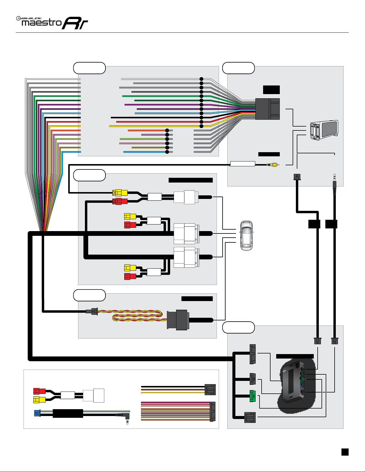
WIRING DIAGRAM
STEP 1
STEP 2
STEP 4
STEP 5
MAESTRO RR MODULE
WHITE - LF SPEAKER (+)
WHITE/BLACK - LF SPEAKER (-)
GRAY - RF SPEAKER (+)
GRAY/BLACK - RF SPEAKER (-)
GREEN - LR SPEAKER (+)
GREEN/BLACK - LR SPEAKER (-)
PURPLE/BLACK - RR SPEAKER (-)
YELLOW - 12V (+)
BLACK - GROUND
RED - ACCESSORY (+)
ORANGE - ILLUMINATION (+)
PURPLE/WHITE - REVERSE LIGHT (+)
LTGREEN - E-BRAKE (-)
BLUE/WHITE - AMP. TURN ON (+)
MAIN
HARNESS
DATA
CABLE
AUDIO
CABLE
PURPLE - RR SPEAKER (+)
CONNECT TO
AFTERMARKET RADIO
HK1 T-HARNESS
FACTORY RADIO
HARNESS
WIRES FROM
VEHICLE
PINK - VEHICLE SPEED
YELLOW/BLACK - FOOT BRAKE
READ NOTE IN
INSTALLATION
INSTRUCTIONS
SECTION
STEP 3 OBDII CONNECTOR
PIONEER RADIO: ENSURE THAT NOTHING
IS PLUGGED IN W/R PORT.
CONNECTION NOT REQUIRED
STEERING WHEEL
CONTROL CABLE
N.C.
N.C.
N.C.
N.C.
N.C.
SEE RADIO
WIRE
REFERENCE
CHART FOR
RADIO WIRE
COLORS
BLUE - POWER ANTENNA
ADS-RR(SR)-HK1-DS-IG-EN maestro.idatalink.com
Hyundai accent all trims 2012-2017
Automotive Data Solutions Inc. © 2021 5
RADIO WIRE REFERENCE CHART
Wire
Description Polarity Wire Color on Maestro
T-Harness
Wire Color on Alpine
cable
Wire Color on Kenwood
cable
Wire Color on Pioneer
cable
Wire Color on Sony
cable
Illumination (+) Orange N/A Orange/White Orange/White Orange
Reverse Light (+) Purple/White Orange/White Purple/White Purple/White Purple/White
E-Brake (-) Lt Green Yellow/Blue Lt Green Lt Green Lt Green
Foot Brake (+) Yellow/Black Yellow/Black N/A Pink N/A
VSS (vehicle speed sensor) (DATA) Pink Green/White Pink Pink N/A
Power Antenna (+) Blue Blue Blue N/A Blue

ADS-RR(SR)-HK1-DS-IG-EN maestro.idatalink.com
Hyundai accent all trims 2012-2017
Automotive Data Solutions Inc. © 2021 6
TROUBLESHOOTING TABLE
PROBLEM SOLUTION
Gauges do not work, radio shows OBD2 Error 1 or Error 2. Refer to STEP 3 in the wiring diagram.
Ensure OBDII connector is securely attached to the OBDII connector of the
vehicle (if applicable).
or
Ensure the RED/ BROWN wire of the HK1 harness and the YELLOW/
BROWN wire of the HK1 harness are connected as shown.
Do not use T-Taps. Soldering or military splicing methods are recommended.
If anything else is connected to the OBD2 or CAN wires of vehicle
(programmer, throttle controller, insurance tracker, etc.) try unplugging it to
see if gauges work. If gauges work without it installed, call tech support for
options.
Reset the RR.
The light on the Maestro is blinking RED TWICE and the radio IS turning on. Ensure the 4-pin data cable is connected between the radio and the RR, and
that it is plugged into the black port on the Maestro RR. The red and blue
ports on the RR should be empty.
Make sure the correct radio model and serial number were entered during
the flash. Verify the radio’s serial number entered during the flash matches
what is listed on the radio screen. This can be found in the settings of the
radio, listed as Device Id, Device Number, or Serial Number.
The light on the Maestro is blinking RED TWICE but radio is NOT turning on. If installing a floating screen type radio and it is not turning on, ensure the
screen is secured and any trim pieces on the radio have been installed fully.
Not installing these fully will prevent radio from powering up and show a 2x
red error as well.
The light on the Maestro is flashing RED ONCE. There is no firmware on the module; flash the RR module.
MAESTRO RR RESET PROCEDURE:
Turn the key to the OFF position, then disconnect all connectors from the module.
Press and hold the module’s programming button and connect all the connectors back to the module. Wait, the module’s LED will flash RED rapidly (this may
take up to 10 seconds).
Release the programming button. Wait, the LED will turn solid GREEN for 2 seconds to show the reset was successful.
TECHNICAL ASSISTANCE
Phone: 1-866-427-2999
Email: maestr[email protected]
Web: maestro.idatalink.com/support add www.12voltdata.com/forum/
IMPORTANT: To ensure proper operation, the aftermarket radio needs to have the latest firmware from the manufacturer. Please visit the radio
manufacturer’s website and look for any updates pertaining to your radio.

ELECTRONICS
Click here for:
Radar Installation Guides
2013
Hyundai elantra Gt
all trims
INSTALL GUIDE
RETAINS STEERING WHEEL CONTROLS, BACKUP CAMERA, GAUGES, AND MORE!
NOTICE: Automotive Data Solutions Inc. (ADS) recommends having this installation performed by a certified technician. Logos and trademarks used here
in are the properties of their respective owners.
PRODUCTS REQUIRED
iDatalink Maestro RR or RR2 Radio Replacement Interface
iDatalink Maestro HRN-RR-HK1 Installation Harness
PROGRAMMED FIRMWARE
ADS-RR(SR)-HK01-DS
ADDITIONAL RESOURCES
Maestro RR2 Programmable Outputs Guide
OR
OPTIONAL ACCESSORIES
ADS-RR(SR)-HK1-DS-IG-EN maestro.idatalink.com
Hyundai elantra Gt all trims 2013
Automotive Data Solutions Inc. © 2021 2
WELCOME
NEED HELP?
Congratulations on the purchase
of your iDatalink Maestro RR Radio
replacement solution. You are
now a few simple steps away from
enjoying your new car radio with
enhanced features.
Before starting your installation,
please ensure that your iDatalink
Maestro module is programmed
with the correct firmware for your
vehicle and that you carefully review
the install guide.
Please note that Maestro RR will
only retain functionalities that
were originally available in the
vehicle.
TABLE OF CONTENTS
Installation Instructions 3
Wiring Diagram 4
Radio Wire Reference Chart 5
Troubleshooting Table 6
1 866 427-2999
maestro.idatalink.com/support
www.12voltdata.com/forum

ADS-RR(SR)-HK1-DS-IG-EN maestro.idatalink.com
Hyundai elantra Gt all trims 2013
Automotive Data Solutions Inc. © 2021 3
INSTALLATION INSTRUCTIONS
STEP 1
• Unbox the aftermarket radio and locate its main harness.
• Connect the wires shown on the next page from
aftermarket radio main harness to the HK1 T-harness and
match the wire functions.
STEP 2
• Remove the factory radio.
• Assemble the HK1 T-harness (connect CAM1 connectors as
shown in the diagram).
• Connect the factory radio harness to the HK1 T-harness.
STEP 3
• Plug the male BLACK 2 pin connector of your HK1
T-harness into the OBDII harness.
• Plug the OBDII connector into the OBDII of the vehicle,
located under the driver side dash.
STEP 4
• Plug the aftermarket radio harnesses into the aftermarket
radio.
• Plug the backup camera RCA into the aftermarket radio (if
applicable).
• Plug the Data cable to the data port of the aftermarket
radio.
• Insert the Audio cable into the iDatalink 3.5 mm audio jack
of the aftermarket radio (If there is no iDatalink audio input,
connect to AUX).
Note: On Pioneer radio, ensure that there is nothing plugged
into the W/R port.
STEP 5
• Connect all the harnesses to the Maestro RR module then
test your installation.
1

ADS-RR(SR)-HK1-DS-IG-EN maestro.idatalink.com
Hyundai elantra Gt all trims 2013
Automotive Data Solutions Inc. © 2021 4
1
BACKUP CAMBACKUP CAM
CAM 3CAM 3
CAM 4CAM 4
CAM 1CAM 1
CAM 2CAM 2
WIRING DIAGRAM
STEP 1
STEP 2
STEP 4
STEP 5
MAESTRO RR MODULE
WHITE - LF SPEAKER (+)
WHITE/BLACK - LF SPEAKER (-)
GRAY - RF SPEAKER (+)
GRAY/BLACK - RF SPEAKER (-)
GREEN - LR SPEAKER (+)
GREEN/BLACK - LR SPEAKER (-)
PURPLE/BLACK - RR SPEAKER (-)
YELLOW - 12V (+)
BLACK - GROUND
RED - ACCESSORY (+)
ORANGE - ILLUMINATION (+)
PURPLE/WHITE - REVERSE LIGHT (+)
LTGREEN - E-BRAKE (-)
BLUE/WHITE - AMP. TURN ON (+)
MAIN
HARNESS
DATA
CABLE
AUDIO
CABLE
PURPLE - RR SPEAKER (+)
CONNECT TO
AFTERMARKET RADIO
HK1 T-HARNESS
FACTORY RADIO
HARNESS
WIRES FROM
VEHICLE
PINK - VEHICLE SPEED
YELLOW/BLACK - FOOT BRAKE
RED
RCA CABLES READ NOTE IN
INSTALLATION
INSTRUCTIONS
SECTION
STEP 3 OBDII CONNECTOR
PIONEER RADIO: ENSURE THAT NOTHING
IS PLUGGED IN W/R PORT.
CONNECTION NOT REQUIRED STEERING WHEEL
CONTROL CABLE
N.C.
N.C.
YELLOW
SEE RADIO
WIRE
REFERENCE
CHART FOR
RADIO WIRE
COLORS
BLUE - POWER ANTENNA

ADS-RR(SR)-HK1-DS-IG-EN maestro.idatalink.com
Hyundai elantra Gt all trims 2013
Automotive Data Solutions Inc. © 2021 5
RADIO WIRE REFERENCE CHART
Wire
Description Polarity Wire Color on Maestro
T-Harness
Wire Color on Alpine
cable
Wire Color on Kenwood
cable
Wire Color on Pioneer
cable
Wire Color on Sony
cable
Illumination (+) Orange N/A Orange/White Orange/White Orange
Reverse Light (+) Purple/White Orange/White Purple/White Purple/White Purple/White
E-Brake (-) Lt Green Yellow/Blue Lt Green Lt Green Lt Green
Foot Brake (+) Yellow/Black Yellow/Black N/A Pink N/A
VSS (vehicle speed sensor) (DATA) Pink Green/White Pink Pink N/A
Power Antenna (+) Blue Blue Blue N/A Blue
ADS-RR(SR)-HK1-DS-IG-EN maestro.idatalink.com
Hyundai elantra Gt all trims 2013
Automotive Data Solutions Inc. © 2021 6
TROUBLESHOOTING TABLE
PROBLEM SOLUTION
Gauges do not work, radio shows OBD2 Error 1 or Error 2. Refer to STEP 3 in the wiring diagram.
Ensure OBDII connector is securely attached to the OBDII connector of the
vehicle (if applicable).
or
Ensure the RED/ BROWN wire of the HK1 harness and the YELLOW/
BROWN wire of the HK1 harness are connected as shown.
Do not use T-Taps. Soldering or military splicing methods are recommended.
If anything else is connected to the OBD2 or CAN wires of vehicle
(programmer, throttle controller, insurance tracker, etc.) try unplugging it to
see if gauges work. If gauges work without it installed, call tech support for
options.
Reset the RR.
The light on the Maestro is blinking RED TWICE and the radio IS turning on. Ensure the 4-pin data cable is connected between the radio and the RR, and
that it is plugged into the black port on the Maestro RR. The red and blue
ports on the RR should be empty.
Make sure the correct radio model and serial number were entered during
the flash. Verify the radio’s serial number entered during the flash matches
what is listed on the radio screen. This can be found in the settings of the
radio, listed as Device Id, Device Number, or Serial Number.
The light on the Maestro is blinking RED TWICE but radio is NOT turning on. If installing a floating screen type radio and it is not turning on, ensure the
screen is secured and any trim pieces on the radio have been installed fully.
Not installing these fully will prevent radio from powering up and show a 2x
red error as well.
The light on the Maestro is flashing RED ONCE. There is no firmware on the module; flash the RR module.
MAESTRO RR RESET PROCEDURE:
Turn the key to the OFF position, then disconnect all connectors from the module.
Press and hold the module’s programming button and connect all the connectors back to the module. Wait, the module’s LED will flash RED rapidly (this may
take up to 10 seconds).
Release the programming button. Wait, the LED will turn solid GREEN for 2 seconds to show the reset was successful.
TECHNICAL ASSISTANCE
Phone: 1-866-427-2999
Email: maestr[email protected]
Web: maestro.idatalink.com/support add www.12voltdata.com/forum/
IMPORTANT: To ensure proper operation, the aftermarket radio needs to have the latest firmware from the manufacturer. Please visit the radio
manufacturer’s website and look for any updates pertaining to your radio.

ELECTRONICS
Click here for:
Radar Installation Guides
2016-2017
Hyundai elantra Gt
witH naV witHout amP
INSTALL GUIDE
RETAINS STEERING WHEEL CONTROLS, BACKUP CAMERA, GAUGES, AND MORE!
NOTICE: Automotive Data Solutions Inc. (ADS) recommends having this installation performed by a certified technician. Logos and trademarks used here
in are the properties of their respective owners.
PRODUCTS REQUIRED
iDatalink Maestro RR or RR2 Radio Replacement Interface
iDatalink Maestro HRN-RR-HK1 Installation Harness
PROGRAMMED FIRMWARE
ADS-RR(SR)-HK01-DS
ADDITIONAL RESOURCES
Maestro RR2 Programmable Outputs Guide
OR
OPTIONAL ACCESSORIES

ADS-RR(SR)-HK1-DS-IG-EN maestro.idatalink.com
Hyundai elantra Gt witH naV witHout amP 2016-2017
Automotive Data Solutions Inc. © 2021 2
WELCOME
NEED HELP?
Congratulations on the purchase
of your iDatalink Maestro RR Radio
replacement solution. You are
now a few simple steps away from
enjoying your new car radio with
enhanced features.
Before starting your installation,
please ensure that your iDatalink
Maestro module is programmed
with the correct firmware for your
vehicle and that you carefully review
the install guide.
Please note that Maestro RR will
only retain functionalities that
were originally available in the
vehicle.
TABLE OF CONTENTS
Installation Instructions 3
Wiring Diagram 4
Radio Wire Reference Chart 5
Troubleshooting Table 6
1 866 427-2999
maestro.idatalink.com/support
www.12voltdata.com/forum

ADS-RR(SR)-HK1-DS-IG-EN maestro.idatalink.com
Hyundai elantra Gt witH naV witHout amP 2016-2017
Automotive Data Solutions Inc. © 2021 3
INSTALLATION INSTRUCTIONS
STEP 1
• Unbox the aftermarket radio and locate its main harness.
• Connect the wires shown on the next page from
aftermarket radio main harness to the HK1 T-harness and
match the wire functions.
STEP 2
• Remove the factory radio.
• Assemble the HK1 T-harness (connect CAM4 connectors as
shown in the diagram).
• Connect the factory radio harness to the HK1 T-harness.
STEP 3
• Plug the male BLACK 2 pin connector of your HK1
T-harness into the OBDII harness.
• Plug the OBDII connector into the OBDII of the vehicle,
located under the driver side dash.
STEP 4
• Plug the aftermarket radio harnesses into the aftermarket
radio.
• Plug the backup camera RCA into the aftermarket radio (if
applicable).
• Plug the Data cable to the data port of the aftermarket
radio.
• Insert the Audio cable into the iDatalink 3.5 mm audio jack
of the aftermarket radio (If there is no iDatalink audio input,
connect to AUX).
Note: On Pioneer radio, ensure that there is nothing plugged
into the W/R port.
STEP 5
• Connect all the harnesses to the Maestro RR module then
test your installation.
4
ADS-RR(SR)-HK1-DS-IG-EN maestro.idatalink.com
Hyundai elantra Gt witH naV witHout amP 2016-2017
Automotive Data Solutions Inc. © 2021 4
4
BACKUP CAMBACKUP CAM
CAM 1CAM 1
CAM 2CAM 2
CAM 4CAM 4
CAM 3CAM 3
WIRING DIAGRAM
STEP 1
STEP 2
STEP 4
STEP 5
MAESTRO RR MODULE
WHITE - LF SPEAKER (+)
WHITE/BLACK - LF SPEAKER (-)
GRAY - RF SPEAKER (+)
GRAY/BLACK - RF SPEAKER (-)
GREEN - LR SPEAKER (+)
GREEN/BLACK - LR SPEAKER (-)
PURPLE/BLACK - RR SPEAKER (-)
YELLOW - 12V (+)
BLACK - GROUND
RED - ACCESSORY (+)
ORANGE - ILLUMINATION (+)
PURPLE/WHITE - REVERSE LIGHT (+)
LTGREEN - E-BRAKE (-)
BLUE/WHITE - AMP. TURN ON (+)
MAIN
HARNESS
DATA
CABLE
AUDIO
CABLE
PURPLE - RR SPEAKER (+)
CONNECT TO
AFTERMARKET RADIO
HK1 T-HARNESS
FACTORY RADIO HARNESS
WIRES FROM
VEHICLE
PINK - VEHICLE SPEED
YELLOW/BLACK - FOOT BRAKE
YELLOW
RED
N.C.
N.C.
N.C.
N.C.
RCA CABLES READ NOTE IN
INSTALLATION
INSTRUCTIONS
SECTION
STEP 3 OBDII CONNECTOR
PIONEER RADIO: ENSURE THAT NOTHING
IS PLUGGED IN W/R PORT.
CONNECTION NOT REQUIRED
STEERING WHEEL
CONTROL CABLE
SEE RADIO
WIRE
REFERENCE
CHART FOR
RADIO WIRE
COLORS
BLUE - POWER ANTENNA

ADS-RR(SR)-HK1-DS-IG-EN maestro.idatalink.com
Hyundai elantra Gt witH naV witHout amP 2016-2017
Automotive Data Solutions Inc. © 2021 5
RADIO WIRE REFERENCE CHART
Wire
Description Polarity Wire Color on Maestro
T-Harness
Wire Color on Alpine
cable
Wire Color on Kenwood
cable
Wire Color on Pioneer
cable
Wire Color on Sony
cable
Illumination (+) Orange N/A Orange/White Orange/White Orange
Reverse Light (+) Purple/White Orange/White Purple/White Purple/White Purple/White
E-Brake (-) Lt Green Yellow/Blue Lt Green Lt Green Lt Green
Foot Brake (+) Yellow/Black Yellow/Black N/A Pink N/A
VSS (vehicle speed sensor) (DATA) Pink Green/White Pink Pink N/A
Power Antenna (+) Blue Blue Blue N/A Blue

ADS-RR(SR)-HK1-DS-IG-EN maestro.idatalink.com
Hyundai elantra Gt witH naV witHout amP 2016-2017
Automotive Data Solutions Inc. © 2021 6
TROUBLESHOOTING TABLE
PROBLEM SOLUTION
Gauges do not work, radio shows OBD2 Error 1 or Error 2. Refer to STEP 3 in the wiring diagram.
Ensure OBDII connector is securely attached to the OBDII connector of the
vehicle (if applicable).
or
Ensure the RED/ BROWN wire of the HK1 harness and the YELLOW/
BROWN wire of the HK1 harness are connected as shown.
Do not use T-Taps. Soldering or military splicing methods are recommended.
If anything else is connected to the OBD2 or CAN wires of vehicle
(programmer, throttle controller, insurance tracker, etc.) try unplugging it to
see if gauges work. If gauges work without it installed, call tech support for
options.
Reset the RR.
The light on the Maestro is blinking RED TWICE and the radio IS turning on. Ensure the 4-pin data cable is connected between the radio and the RR, and
that it is plugged into the black port on the Maestro RR. The red and blue
ports on the RR should be empty.
Make sure the correct radio model and serial number were entered during
the flash. Verify the radio’s serial number entered during the flash matches
what is listed on the radio screen. This can be found in the settings of the
radio, listed as Device Id, Device Number, or Serial Number.
The light on the Maestro is blinking RED TWICE but radio is NOT turning on. If installing a floating screen type radio and it is not turning on, ensure the
screen is secured and any trim pieces on the radio have been installed fully.
Not installing these fully will prevent radio from powering up and show a 2x
red error as well.
The light on the Maestro is flashing RED ONCE. There is no firmware on the module; flash the RR module.
MAESTRO RR RESET PROCEDURE:
Turn the key to the OFF position, then disconnect all connectors from the module.
Press and hold the module’s programming button and connect all the connectors back to the module. Wait, the module’s LED will flash RED rapidly (this may
take up to 10 seconds).
Release the programming button. Wait, the LED will turn solid GREEN for 2 seconds to show the reset was successful.
TECHNICAL ASSISTANCE
Phone: 1-866-427-2999
Email: maestr[email protected]
Web: maestro.idatalink.com/support add www.12voltdata.com/forum/
IMPORTANT: To ensure proper operation, the aftermarket radio needs to have the latest firmware from the manufacturer. Please visit the radio
manufacturer’s website and look for any updates pertaining to your radio.

ELECTRONICS
Click here for:
Radar Installation Guides
2018
Hyundai elantra Gt
witH naV witHout amP
INSTALL GUIDE
RETAINS STEERING WHEEL CONTROLS, BACKUP CAMERA, GAUGES, AND MORE!
NOTICE: Automotive Data Solutions Inc. (ADS) recommends having this installation performed by a certified technician. Logos and trademarks used here
in are the properties of their respective owners.
PRODUCTS REQUIRED
iDatalink Maestro RR or RR2 Radio Replacement Interface
iDatalink Maestro HRN-RR-HK1 Installation Harness
PROGRAMMED FIRMWARE
ADS-RR(SR)-HK01-DS
ADDITIONAL RESOURCES
Maestro RR2 Programmable Outputs Guide
OR
OPTIONAL ACCESSORIES
Other manuals for iDatalink Maestro RR
1
Other Automotive Data Solutions Automobile Accessories manuals

Automotive Data Solutions
Automotive Data Solutions iDataStart 99998HC1451AN User manual

Automotive Data Solutions
Automotive Data Solutions BLADE-AL-TL5-EN User manual

Automotive Data Solutions
Automotive Data Solutions HCX000A User manual

Automotive Data Solutions
Automotive Data Solutions FIRSTECH FT-DC3-LC User manual

Automotive Data Solutions
Automotive Data Solutions RSA-SUB2 User manual

Automotive Data Solutions
Automotive Data Solutions TR2410ATL User manual


