6
Westin Automotive Products, Inc.
320 W. Covina Blvd
San Dimas, Ca. 91773
Thank you for choosing Westin products
for additional installation assistance please call
Customer Service (800) 793-7846
www.westinautomotive.com
P.N.: 75-2924085-RevA ECO #: W23-0047 DATE: 09/11/2023
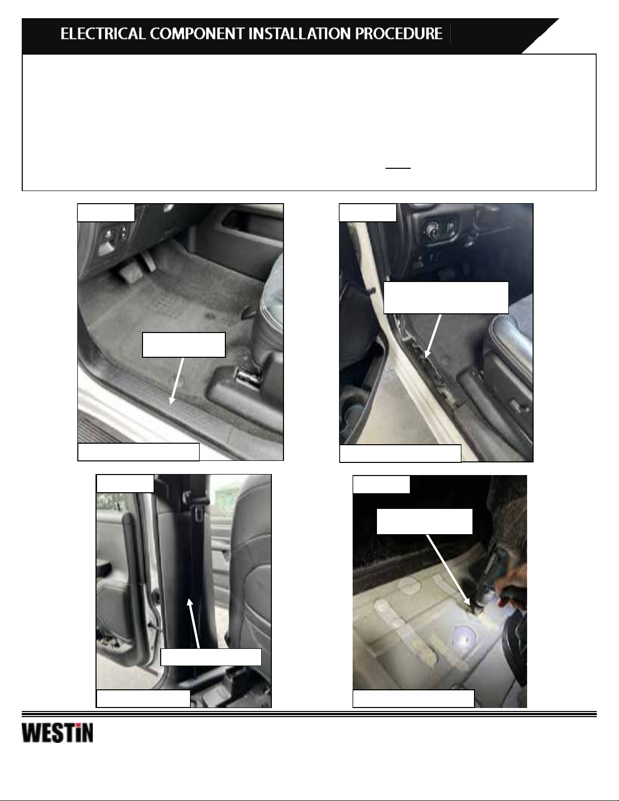
Figure 5
Front Driver Side Shown
4. Route the driver side brown door trigger wire to the driver side B-Pillar, and the passenger side white door trigger wire
under the front driver side carpet, the center console, the front passenger side carpet, and to the passenger side B-Pillar.
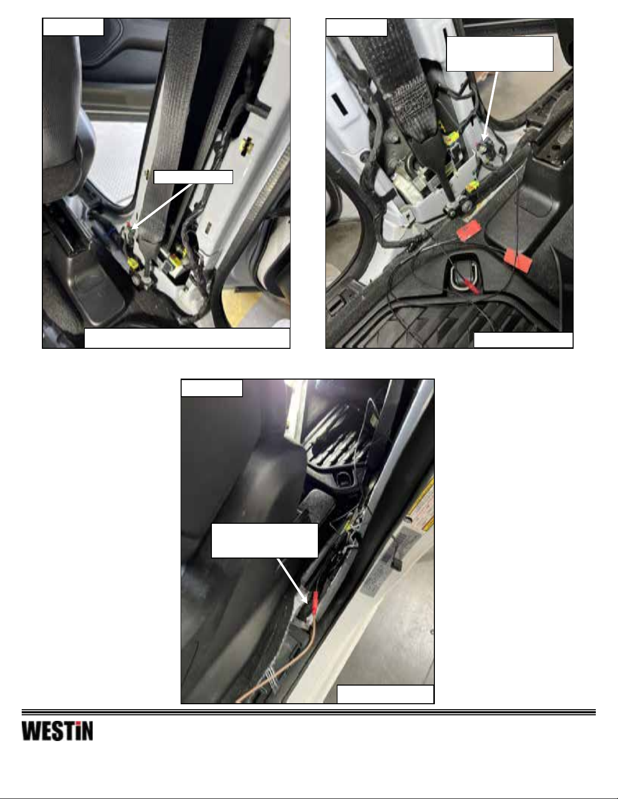
5. With the B-Pillar panels removed, locate the seat belt assembly on the driver’s side and loosen the top bolt shown. Locate
the Magnetic Induction Module (Item 9) and mount the ground wire fork under the top bolt of the seat belt assembly to
provide a ground connection for the Magnetic Induction Module. Once grounded, connect the snap-in bullet connector on
the module to the brown trigger wire previously routed to the driver side B-Pillar. See Figure 6 through 8 for reference.
6. Prepare the “sticking” surfaces on both sides of the B-Pillar by using a damp rag with a mix of isopropyl alcohol and water
to clean the surface. Once the surface is completely dry, remove the backing from the Magnetic Induction Module, and
“stick” them onto both sides of the B-Pillar as shown in Figures 9 & 10. Note: Pay close attention to where the Magnetic
Induction Modules are placed on the door jambs of the vehicle.
7. Using a measuring tape and masking tape, take reference of where the Magnetic Induction Modules have been placed on
the front driver side door jamb and rear driver side door jamb so that the magnets can be placed accordingly on the door
strikers. Once a reference point has been taken, place the reference masking tape onto the driver side door striker and rear
driver side door striker, respectively, and prepare the surface on the door strikers by using a damp rag with a mix of isopro-
pyl alcohol and water to clean the surface. Once the surface is completely dry, peel the backing from the magnets and
“stick” them to the reference location on the door striker. See Figures 11 & 12 for reference.
8. Repeat Steps 5 through 7 for the white trigger wire that was previously routed to the passenger side B-Pillar.
Note: Pay attention to measurements and positions shown for the Magnetic Induction Module and magnets. The magnet must
align with the corresponding module sensor to ensure the motor linkages function properly. If the boards are not deploying
once all of the wiring is connected, inspect and ensure that the magnets align with their corresponding module sensor.
Wires routed into the drilled open-
ing on the front driver side carpet.