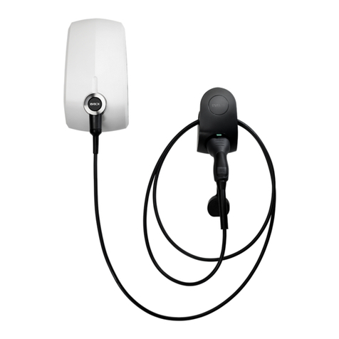
EVBox BusinessLine User manual

Installation an user manual
1
EVBox
BusinessLine

I'm here
Let's get starte .

EVBox
BusinessLine
Installation an user manual


Contents
1. Intro uction 3
1.1. Compatibility 3
1.2. Get in touch 3
1.3. Pro uct classification 3
1.4. Pro uct an environmental characteristics 4
2. Safety precautions 5
2.1. Warning: Risk of electric shock 5
2.2. Warning: Accumulation of gasses 5
2.3. Cautions: 5
2.4. Transport an storage 6
3. Components 7
3.1. Delivere components 7
3.2. Optional components 7
4. Pro uct features 9
4.1. BusinessLine configurations 9
4.2. Connecting BusinessLine 9
4.3. Description 9
4.4. Controller connections 10
5. Technical specifications 12
6. Prepare for installation 14
6.1. Safety precautions 14
6.2. Plan installation 14
6.3. Choose location 14
6.4. Hub-Satellite installations 15
6.5. Route power supply cables 15
6.6. Phase rotation 16
6.7. Power configuration for smart gri 16
6.8. Choose mounting 16
7. Install charging station 19
7.1. Remove covers 19
7.2. Install station 20
7.3. Finish installation 23
8. Configure Hub-Satellite 26
8.1. Connect ata cables 26
9. Activate BusinessLine 28
9.1. Using Wi-Fi with BusinessLine 28
EN
1

1. Introduction
Thank you for choosing the EVBox BusinessLine, our best-selling charging station with proven technology an
reliability. Built to be connecte an intelligent, EVBox BusinessLine makes going electric at your workplace or
business easier than ever.
This Installation an User manual tells you how to install an use the EVBox BusinessLine. Carefully rea the
safety information before you start.
These instructions are vali for several mo els of the charging station. It is possible that some features an
options escribe may not apply to your charging station.
1.1. Compatibility
The EVBox BusinessLine generation 4 is not compatible with earlier generations of the BusinessLine charging
station. Each Hub-Satellite installation must consist of the same generation of charging stations.
1.2. Get in touch
If you have any suggestions how we can improve our pro ucts, or if you see an error, we’ love to hear from
you. You can contact us by going to evbox.com/support.
All EVBox manuals can be ownloa e from evbox.com/manuals.
1.3. Product classi?cation
This pro uct has the following classification:
Table 1. Classification
Power supply input EV supply equipment permanently connecte to
AC supply network.
Power supply output AC EV supply equipment.
Normal environmental con itions Out oor use.
Access Equipment for locations with unrestricte
access.
Mounting metho Stationary equipment, surface-mounte on
walls, poles or brackets.
Protection against electric shock Class 1 equipment.
1. Introduction EN
3

Charging mo es Mo e 3.
1.4. Product and environmental characteristics
The charging station has been CE-certifie by the manufacturer an bears the CE logo. The relevant
eclaration of conformity may be obtaine from the manufacturer. The charging station complies with the
RoHS Directive (RL 2011/65/EU). The relevant eclaration of conformity may be obtaine from the
manufacturer. Electrical an electronic appliances, inclu ing accessories, must be ispose of separately from
the general municipal soli waste. Recycling of materials saves raw materials an energy an makes a major
contribution to conserving the environment.
EN 1. Introduction
4

2. Safety precautions
Rea an obey the following safety precautions before you install, service or use your charging station. The
installer must ensure that the charging station is installe in accor ance with the relevant country-specific
stan ar s an local regulations.
2.1. Warning: isk of electric shock
• Switch off input power to your charging station before you install or service the charging station.
Keep the power off until the charging station is fully installe with its covers installe an secure .
• In the event of anger an /or an acci ent, a certifie electrician must imme iately isconnect the
electrical supply from the charging station.
• Do not operate the charging station if it is physically amage or if the charging cable has cracks,
excessive wear, or other visible amage. Contact EVBox or your istributor if you suspect that the
charging station is amage .
• Do not irect powerful jets of water towar or onto the charging station. Never operate it with wet
han s. Do not put the EV charging plug into any liqui .
• Do not put fingers or other objects insi e the charging port or plug port.
• Rea the user instructions elivere with your EVBox charging station an the User Manual for
your electric vehicle before charging your vehicle.
2.2. Warning: Accumulation of gasses
• Some electric vehicles require an external ventilation system to prevent the accumulation of
hazar ous or explosive gasses when charging in oors. Refer to your vehicle User Manual to check
if your vehicle releases hazar ous or explosive gasses when charging.
2.3. Cautions:
• Use this charging station to charge Mo e 3 compatible electric vehicles only. Refer to your vehicle
User Manual to check if your vehicle is compatible.
• This charging station may affect implante electronic me ical evices. Before you charge your
vehicle, consult the supplier of the electronic me ical evice to etermine if it can be influence
by charging effects.
2. Safety precautions EN
5

• This charging station may only be installe , service , relocate an repaire by qualifie persons.
Incorrect installation, repairs or mo ification can result in anger to the user an may voi the
warranty an liability.
• This charging station contains no user-serviceable parts. The user must not attempt to service,
repair or relocate the charging station. Contact EVBox or your ealer for more information.
• Make sure that the charging cable cannot become amage (kinke , jamme or riven over) an
that the plug(s) o not come into contact with heat sources, irt or water.
• Only use the charging station un er the specifie operating con itions.
• Do not use explosives or flammable substances near the charging station.
• If you are unsure about how to use a charging station, ask for help.
• Do not allow chil ren to operate a charging station. A ult supervision is require when chil ren
are near a charging station that is in use.
• Make sure that the charging cable is positione so that it will not be steppe on, trippe over,
riven over or otherwise subjecte to excessive force or amage.
• While charging, the cable must be completely unwoun an connecte to the vehicle without
overlapping loops (this is to avoi the risk of the charging cable overheating).
• Only pull on the charging plug han grip an never on the charging cable itself.
• A apters, conversion a apters or cor extensions must never be use on this charging station.
2.4. Transport and storage
• Disconnect input power before removing the charging station for storage or relocation.
• Only transport an store the charging station in its original packaging. No liability can be accepte
for amage incurre when the pro uct is transporte in non-stan ar packaging.
• Store the charging station in a ry environment in the temperature range given in the
specifications.
EN 2. Safety precautions
6

3. Components
3.1. Delivered components
The elivere components will epen on the mo el, type of installation, an the selecte mounting option.
Table 2. Delivere components
1x EVBox
BusinessLine unit
(single or ouble
socket, satellite an /
or hub).
EVBox Connector
set (for hub-satellite
installations, supplie
with each satellite).
1x EVBox
BusinessLine cover
(for a single socket).
2x EVBox
BusinessLine covers
(for a ouble socket).
1x Hex key (to open
the cover of the unit).
1x Ground cable.
1x Instructions
folder (Installation
an User manual,
security co e an the
station ID).
3.2. Optional components
Depen ing on the installation, the following components can also be require . Contact your supplier to or er
the optional components.
Note: The installer is responsible supplying the power cables, ata cables an any minor items
require for the installation.
3. Components EN
7

Table 3. Optional components
Component Part number
EVBox Combipole (IN the groun ) 290150
EVBox Combipole (ON the groun ) 290305
EVBox Combipole (Wall mounte ) 290600
EVBox Adapter Kit (to install a single station on a Combipole) 290165
EVBox Wall spacer (to install a single station on a wall) 290190
120 Ω resistor (to terminate the RS485 connector of last satellite charging station
in a hub-satellite installation) 470041
EVBox Test Box with ?xed cable (to test the functioning of the charging station) 462322
EN 3. Components
8

4. Product features
The BusinessLine charging station is compatible with all Mo e 3 electric vehicles an is esigne for both
in oor an out oor use. Operation of the charging station is approve at ambient temperatures of between
-25 °C an +50 °C. The charging station can be connecte to a central system for the registration of the
number of kilowatt-hours (kWh) charge .
4.1. BusinessLine con?gurations
BusinessLine charging stations come in the following configurations:
• Single socket, communications hub.
• Single socket, satellite.
• Double socket, one communications hub an one satellite.
• Double socket, two satellites.
One BusinessLine hub can be connecte to a maximum of 19 BusinessLine satellites. A smart gri can be
establishe over all charging stations. This optimizes power usage an lets more vehicles charge
simultaneously shoul power limitations exist.
4.2. Connecting BusinessLine
A charging station has an RFID car rea er an a kWh meter. A communications hub is built into a hub-
type charging station. The communications hub has a cellular ata connection, Wi-Fi, Bluetooth an
GPS which have the following functions:
Connection Description
Cellular ata connection (2G,
3G an 4G)
Connection to backen systems for setup, maintenance an
transactions (metho 1).
Wi-Fi Connection to backen systems for setup, maintenance an
transactions (metho 2).
Bluetooth Local setup an access control for the charging stations.
GPS Location of the charging stations.
4.3. Description
4. Product features EN
9

Description
1. Operation
BusinessLine is connecte using either a built-in or
remote ual ban Wi-Fi connection or a cellular mo em.
To start or stop a charging session, use a registere
charge car , key fob, or the Hey EVBox app.
When use in Autostart mo e, a registere charge car ,
key fob, or Hey EVBox app is not require . Charging
starts automatically when the charging station is
connecte to a vehicle.
2. FID reader
This is the area where you scan an RFID car or key fob.
The BusinessLine rea s the ata from the car or fob to
start or stop a charging session. If the charging station is
not connecte to a vehicle an is not activate by the
RFID car or fob, there is no voltage on the socket an
the charging session will not start.
3. LED indicator ring and socket
The LED in icator ring aroun the socket shows the
status an mo e of the charging station at all times. The
socket lets you use your own charging cable. The socket
is a stan ar Type 2 with an optionally integrate shutter
system.
4.4. Controller connections
EN 4. Product features
10

Connection group Description
1 - 2 pin, re External relay
2 - 2 pin, blue kWh meter
3 - 2 pin, black RS485 hub-satellite communication
4 - 4 pin, green Inputs
5 - 2 pin, gray RS485 smart charging communication
6 - 2 pin, green Temperature sensor
7 - 3 pin, green Pilot
8 - 4 pin, blue LED ring
9 - 3 pin, black Lock motor
4. Product features EN
11

5. Technical speci?cations
Table 4.
Feature Description
Technical features
Charging capacity per socket Maximum 7.4 kW, 11 kW or 22 kW, epen ing on installation an
set-up.
Socket type Type 2.
Number of sockets 1 or 2.
Output power per socket 1-phase or 3-phase, 230 V – 400 V, 16 A or 32 A.
Connection capacity 1-phase or 3-phase, 50 Hz, between 2.5 – 10 mm2.
Resi ual-current Circuit
Breaker with Overcurrent
protection (RCBO)
• Eaton FRBM4-C32/3N/003-A.
• Eaton FRBM6-C16/3N/003-A.
• Eaton FRBM6-C32/3N/003-A.
Resi ual irect current
etecting evice
Complies with IEC 62955, with 6 mA smooth resi ual DC
etection an a itional 30 mA resi ual AC etection .
Operating temperature range -25 °C to +50 °C.
Humi ity (non-regulating) Max. 95%.
Communication GPS / GSM / UMTS / LTE cellular ata, Wi-Fi, Bluetooth an GPS
mo ule controller with RFID rea er (in hub type).
Communication protocol OCPP 1.6 JSON.
Physical features
Certification an compliance See Declaration of conformity on page 39.
Protection IP55, IK08.
Housing Polycarbonate.
Max. installation altitu e 2000 m above sea level.
EN 5. Technical specifications
12

Feature Description
Dimensions (mm)
600 x 255 x 410 mm ( ouble).
600 x 255 x 205 mm (single).
Weight (kg)
12 kg ( ouble socket).
10 kg (single socket).
Mounting
Double: Combipole in or on the groun , or on a wall.
Single: Combipole in or on the groun , or on a wall. Wall spacer
for irect installation on a wall.
Stan ar colors RAL 7016 ( ark gray), RAL 9016 (white), RAL 5017 (blue).
5. Technical specifications EN
13

6. Prepare for installation
The following recommen ations are a gui e to help you prepare for the installation of the EVBox BusinessLine
charging station.
6.1. Safety precautions
You must rea an obey the safety precautions on page 0 at the beginning of this manual before you install,
service or use your EVBox charging station. The installer must ensure that the charging station is installe in
accor ance with the relevant country-specific stan ar s an local regulations.
6.2. Plan installation
• Calculate the existing electrical loa to fin the maximum operating current for the charging
station installation.
• Calculate the istance from the power supply panel to the charging station installation to fin the
voltage rop. Local regulations may be applicable an can vary epen ing upon the region or
country.
• Obtain all necessary permits from the local authority that has juris iction.
• Use only copper con uctors.
• Refer to local wiring regulations to select the con uctor sizes.
• Make sure that there is a equate free space of at least 20 cm aroun the charging station for
ventilation purposes.
• Use the correct tools an provi e sufficient material resources an protection measures.
• Make sure that there is goo cellular an /or Wi-Fi reception where the hub charging station will be
installe .
• Prepare the installation areas with the correct power wiring for each charging station an the ata
cabling between the satellite charging stations an the hub charging station.
6.3. Choose location
Position the charging station, where possible, in surroun ings where it is not expose to extreme sunlight an
vulnerable to external amage.
EN 6. Prepare for installation
14

6.4. Hub-Satellite installations
A Hub-Satellite charging station installation can consist of up to 19 satellite stations connecte to a hub
station. A Hub-Satellite installation is easier an more economical to manage than in ivi ual hubs because it
has only one hub, an it enables a smart gri to be establishe across the connecte stations which optimizes
power usage.
Data communication between the stations uses a RS485 serial ata connection.
For more information see chapter Configure Hub-Satellite on page 26.
6.5. oute power supply cables
The appropriate wire gauge of the supply cable epen s on the power rating an istance between
the meter cabinet an the charging station. The voltage rop must not excee 5% (it is a visable to
have a maximum allowable voltage rop of 3%). The maximum wire gauge that can be fitte is 10
mm2.
The ouble socket mo el can be supplie with connections for one or two power cables. The stan ar
configuration is supply from one power cable to the terminals in the hub unit, with the satellite fe from
these terminals using internal powerline wiring. To connect a power cable separately to each unit,
remove this internal power wiring an connect the satellite unit power cable irectly to the satellite
RCBO.
Route the power supply cables to the position where the charging station will be installe . Make sure
of the following:
• There must be enough cable for it to exten at least 50 cm out of an installe Combipole or Wall
A apter.
• There must be enough cable for it to move sufficiently uring installation of a Combipole.
Note: The power line enters the station via the backplate for single stations, an through the
Combipole for ouble stations.
The maximum power rating for each connector is specifie below.
Power per connector Connection Input current Output current
7.4 kW 1-phase 2x 32 A 2x 32 A
11 kW 3-phase
1x 32 A or
2x 16 A
2x 16 A
6. Prepare for installation EN
15

Power per connector Connection Input current Output current
22 kW 3-phase 2x 32 A 2x 32 A
6.6. Phase rotation
To avoi overloa ing the first phase with one-phase electric vehicles, we recommen rotating the phases as
shown below.
Note: If phase rotation is use you must inform EVBox at www.evbox.com/support so the support
team can up ate the backen system ata.
6.7. Power con?guration for smart grid
For accurate performance of the smart gri , consult with the CPO (Charge Point Operator) to set the maximum
power available on the gri .
• If multiple three-phase satellite charging stations are connecte in the smart gri , it is
recommen e to swap the primary phase to istribute power consumption as evenly as possible
over all phases (see Phase rotation on page 16).
• Make sure that the connector number printe on the Mo e 3 charge box an the phase it uses as
its primary phase match.
• For optimal performance of the smart gri , you must inform your CPO of the configuration. Use
the EVBox Connect app to set-up your BusinessLine rea y for connection to a network.
6.8. Choose mounting
EVBox BusinessLine charging stations can be mounte in the following ways:
Pole mounting in the ground, on the @oor or on a wall
EN 6. Prepare for installation
16
Other manuals for BusinessLine
7
Table of contents
Other EVBox Automobile Accessories manuals