Autopilot ChlorSync CS30 Quick start guide
Owner's / Installation Manual
INSTALLER: THIS DOCUMENT IS PURCHASER’S PROPERTY AND IS TO REMAIN WITH THE EQUIPMENT OWNER
LTP0127 REV 2.0
Important!
This manual covers the installation and operation of the ChlorSync®Chlorine Generators.
Read this manual and product labels before installing or operating this equipment.


Table of Contents
Safety Information
Safety Information 1
General Information
Contacting AquaCal AutoPilot, Inc. 4
How Your Chlorinator Works 4
Quick Start 4
ChlorSync® Model Cell Options 5
Power Center 5
Cell 6
Flow Bypass Kit (Optional) 7
Patented Temperature Compensation 7
Control Panel Overview
User Display 8
Salt Indicator LED 8
Cell Indicator LED 8
Flow Indicator LED 8
Cell Output Control 9
Water Balance and Chemistry Recommendations
Basic Water Chemistry 10
Preparing the Pool Water 13
Using the Saturation Index 14
Adding Salt 15
Salt Addition Information 15
Operation
Basic Operation 16
Sanitizer Output Settings and Adjustments 17
Maintenance
Cleaning the Cell 17
Winterizing 18
Spring Start Up 18
Fuse Replacement 18
Installation
Electrical Installation 19
Pool Cover Detection 20
PoolSyncTM Installation (optional equipment not included) 20
Plumbing Installation 22
Installation Recommendations 22
Connecting the ChlorSync® Cell Cable to the Power Center 23
Installing the Optional Flow Bypass Kit 24
Troubleshooting
Troubleshooting 25
Specifications and Approvals
Agency Approvals 28
FCC Compliance 28
i


Page - 1
SAFETY INFORMATION
Safety Information
IMPORTANT SAFETY INSTRUCTIONS
When installing and using this electrical equipment, basic safety precautions should always be
followed, including the following:
READ AND FOLLOW ALL INSTRUCTIONS
lA green colored terminal or terminal marked G, GR, Ground, Grounding, or the symbol is located
inside the power center terminal box or compartment. To reduce the risk of electric shock, this terminal
must be connected to the grounding means provided in the electric service panel with a continuous
copper wire equivalent in size to the circuit conductors supplying this equipment.
lFollow all state, local, and National Electrical Code(s) (provincial and Canadian Electrical Code(s) if
applicable) unless local guidelines supersede.
lFor personal safety, and to avoid damage to equipment, follow all safety instructions displayed on the
equipment and within this manual. Repair and service of your chlorinator must be performed by qualified
service personnel.
lShould you suspect your chlorine generator is not performing properly, refer to the Troubleshooting
section in this manual to determine if service is required.
lWarranties may be voided if the chlorinator has been improperly installed. Failure to properly operate,
maintain or repair the AutoPilot®chlorinator may void the factory warranty.
SAFETY SIGNALS
Throughout this manual, safety signals are placed where particular attention is
required.
WARNING - Failure to heed the following may result in permanent injury or
death.
CAUTION - Failure to heed the following may result in equipment damage.
WARNING - Failure to heed the following may result in permanent injury or death.
lRISK OF ELECTRICAL SHOCK - Disconnect all AC power when installing or servicing this system.
Follow all state, local, and National Electrical Code(s) (provincial and Canadian Electrical Code(s) if
applicable). Use copper conductors only.
lRISK OF ELECTRICAL SHOCK - To reduce the risk of electrical shock, replace damaged cord
immediately.
lRISK OF ELECTRICAL SHOCK - The AutoPilot®chlorinator contains no owner-repairable
components. Repairs must not be attempted by untrained and/or unqualified individuals. If service is
deemed necessary, contact installing dealer or AquaCal AutoPilot Customer Support.
lRISK OF ELECTRICAL SHOCK - A bonding lug has been provided on the outside of the power center.
This lug permits the connection of a No. 8 AWG (8.4 mm2) solid copper-bonding conductor (No. 6 AWG
in Canada). Make this connection between the AutoPilot®power center and all other electrical
equipment and exposed metal within 5 ft (1.5 m) of the unit. All field-installed metal components (such
as rails, ladders, drains, etc.) within 12 ft (3.6 m) of the pool, spa, or hot tub, must be bonded to the
equipment grounding bus using copper conductors not smaller than No. 8 AWG (8.4 mm2) (No. 6 AWG
in Canada).
lRISK OF ELECTRICAL SHOCK - The AutoPilot®chlorinators must be installed at least 10 ft (3 m) from
the pool or spa wall.
Page - 2
lRISK OF ELECTRICAL SHOCK - A disconnect device incorporated into the fixed wiring must be
included in the supply circuit (such as a time clock, relay, or circuit breaker).
lRISK OF ELECTRICAL SHOCK - Connect only to a branch circuit protected by a ground-fault circuit-
interrupter (GFCI). Contact a qualified electrician if you cannot verify that the circuit is protected by a
GFCI.
lRISK OF ELECTRICAL SHOCK - The chlorinator must be connected only to a supply circuit that is
protected by a ground-fault circuit-interrupter (GFCI). The GFCI must be tested on a routine basis. To
test, push the GFCI test button. Power should be interrupted. Push the reset button. Power should be
restored. If the GFCI fails to operate in this manner, it is defective.
lRISK OF ELECTRICAL SHOCK - If the ground-fault circuit-interrupter (GFCI) interrupts power to the
equipment without the test button being pushed, a ground current is flowing with a possibility of an
electrical shock. Do not use equipment. Disconnect the equipment and have the problem corrected by a
qualified service representative before using.
lRISK OF ELECTRICAL SHOCK - The unit has two bonding lugs marked "Bonding Lugs" that are
provided on the external surface or on the inside of the power supply terminal box or compartment. To
reduce the risk of electric shock, connect the local common bonding grid in the area of the hot tub or spa
to these terminals with an insulated or bare copper conductor not smaller than No. 6 AWG.
SAVE THESE INSTRUCTIONS
WARNING - Failure to heed the following may result in permanent injury or death.
lCHEMICAL HAZARD - To avoid damaging splashes, always add acid to water, never water to acid.
Wear safety glasses and use other appropriate personal protection equipment.
lCHEMICAL HAZARD - Always follow the instructions on the manufacturer's label whenever handling or
using chemicals.
lCHEMICAL HAZARD – Heavy pool (or spa) usage and higher temperatures may require a higher
chlorine output in order to maintain proper free available chlorine residuals.
lWATER CHEMISTRY SAFETY - Improper water chemistry can present a serious health hazard. The
proper residual chlorine level and water chemistry must be maintained. The addition of certain pool
maintenance chemicals can reduce the effectiveness of chlorine. Maintain pool/spa water per standards
detailed later in this manual.
lCOMBUSTIBLE HAZARD – The AutoPilot®chlorinator is equipped with an electronic flow sensor that
automatically turns the unit off in the event of a “low water flow” situation. Do not tamper in any way with
this safety feature.
lPERSONAL SAFETY HAZARD – To reduce the risk of injury, do not permit children to operate this
device.
lRISK OF CHILD DROWNING OR INJURY - Children must be closely supervised at all times around pool
or spa equipment.
CAUTION - Failure to heed the following may result in equipment damage.
lThe ChlorSync®must be installed and operated as specified. Failure to do so will void the equipment
warranty.
lTo permit proper air circulation, the power center must be mounted at least 5 ft (1.5 m) above ground
level or any other air flow obstruction.
lSpecial measures are required in the event of freezing conditions. Your chlorinator may be damaged if
measures are not taken in advance of freezing conditions. Equipment damage due to freezing
conditions is NOT covered under the equipment warranty.
lFor all newly constructed or resurfaced plaster pools: Do not operate the AutoPilot®with newly poured or
resurfaced pool plaster. Before adding salt and operating the chlorinator, wait 30 days after construction
is completed to allow proper curing of the surface material. Follow the pool surface manufacturer’s
guidelines for your specific pool.
lFOR NEW VINYL LINER POOLS, contact the manufacturer for recommended instructions before
adding salt and operating the ChlorSync®.
lDo not allow granular salt to pile up in one location without brushing, as staining may occur.

Page - 3
l
l
l
l
While the recommended level of salt for your AutoPilot® product should not damage your equipment,
excessively high chlorine levels can cause corrosion damage to pool fixtures and equipment. Consult
your pool professional for equipment selection, proper use and maintenance of these products.
For maximum cell life, maintain water in a balanced condition. Water maintained in a scaling condition
will shorten cell life and may render the AutoPilot® chlorinator inoperative. Damage and/or service calls
caused by improper water balance, is NOT covered under the equipment warranty. See "Water Balance
and Chemistry Recommendations" on page 9 for more information.
Scraping or scratching the titanium blade’s edge or surface will damage the blade coating and cause
premature failure of the cell. Never use any sharp or metallic objects to remove scale. The warranty will
be voided. See "Cleaning the Cell" on page 17 for instructions on how to properly clean the cell.
The ChlorSync® reverse polarity times are factory set and can only be changed by using the PoolSyncTM
option. Reduced polarity reversing cycle times will reduce cell life and should only be used due to
uncontrollable scale formation on the cell. ALWAYS test and adjust water balance before attempting
scale control via shortening reverse period.
SAVE THESE INSTRUCTIONS
Page - 4
GENERAL INFORMATION
Contacting AquaCal AutoPilot, Inc.
If you need to contact AquaCal AutoPilot, Inc. for questions, service, or parts, please have your
model and serial numbers available. Also have the name of your installer and date of your
equipment’s installation. Please refer to our website for the latest manual revisions, additional
information, and helpful service advice.
Website www.autopilot.com
Phone (727) 823-5642
Fax (877) 408-8142
Address
AquaCal AutoPilot, Inc.
2737 24th Street North
St. Petersburg, FL 33713, USA
Pool volume
(Gallons / Liters)
Installer
Install Date
Cell Type
Cell Serial #
How Your Chlorinator Works
The ChlorSync®is designed to handle the purification needs of residential and small commercial
swimming pools and spas. The amount of chlorine required for proper sanitization will vary
based on the pool size and factors such as water temperature, bather load, exposure to direct
sunlight, and special water features.
The system requires a low concentration of dissolved salt (sodium chloride) in the water and is
normally maintained below the taste threshold. The AutoPilot®unit uses the salt to generate
chlorine, which your pool/spa requires to remain sanitized. The chlorine reverts back to salt after
treating the water. Since the chlorine generation process does not reduce pool water salinity,
there is minimal loss during a swimming season. Salt can be lost due to filter back washing, rain
water overflow, leaks, or bather splashing/carry out, but not through evaporation.
The water circulation pump must be operating for your chlorinator to produce chlorine, so run
time is one of several key factors to maintaining proper sanitizer levels. Most installations require
a minimum of eight (8) hours-per-day pump run time to properly filter and sanitize the water.
Quick Start
1. Balance the water chemistry according to the water chemistry parameters and salt recommendations.
See "Water Balance and Chemistry Recommendations" on page 9 . See "Preparing the Pool Water"
on page 13.
lThe chlorinator may be started immediately. The salt reading, however, may initially be
inaccurate until the circulation pump has been run for 24 hours to fully dissolve newly added salt.
2. Use the △or▽arrow buttons to set the purifier percentage to 50%.
3. During the first two weeks, test the water chemistry parameters every 3-4 days. Adjust purifier
percentage as needed.
4. Once ideal purifier percentage has been determined, follow normal maintenance procedures.

Page - 5
ChlorSync®Model Cell Options
The ChlorSync®system consists of the following components.
lPart #ECP0312 Power Center- Provides power and controls communication between the power center
and the cell.
lThree different cell options to choose from - CS30, CS40, CS50.
The chlorine output for each of the ChlorSync®models, which is based on a 24 hour chlorinator/
pump run time and a salt concentration of 3,500 ppm (mg/L), is listed in the table below.
Model Chlorine output lbs. (kg) per 24 hours
ChlorSync®
CS30
1.1 lbs. (0.50 kg)
ChlorSync®
CS40
1.4 lbs. (0.64 kg)
ChlorSync®
CS50
1.7 lbs. (0.77 kg)
Power Center
WARNING - Failure to heed the following may result in permanent injury or death.
lRISK OF ELECTRICAL SHOCK - All electrical connections should be made by a licensed electrician or
certified electrical contractor.
lRISK OF ELECTRICAL SHOCK - Disconnect all AC power when installing or servicing this system.
Follow all state, local, and National Electrical Code(s) (provincial and Canadian Electrical Code(s) if
applicable). Use copper conductors only.
lRISK OF ELECTRICAL SHOCK - Before plugging or unplugging the ChlorSync®to the power center,
first switch off the AC power to the power center.
ChlorSync®Power Center
Figure 1

Page - 6
Cell
The cell includes buttons, a digital display, and LED indicators to control the ChlorSync®and
chlorine production. See "User Display" on page 8 for more information. The ChlorSync®unit
measures water flow, water temperature and salt levels. If the salt level in the pool water falls
below 2,300 ppm (mg/L), the unit will not produce chlorine until more salt is added to the body of
water. The cell is equipped with a self-cleaning feature that reverses the cell polarity and
removes normal calcium build up. The self cleaning process occurs at predetermined times
throughout the day.
If the water is excessively unbalanced and scale forming, the self cleaning process may not be
able to remove all scale. See "Water Balance and Chemistry Recommendations" on page 9.
ChlorSync®Cell
Figure 2
The ChlorSync®sanitizer output can be set by adjusting the output level on the control unit. The
pool pump run time, combined with the output setting, will determine how much sanitizer is
produced each day.
The unit is capable of monitoring water flow, water temperature, and salt level with the following
components:
lFlow Sensor: The cell is equipped with a sensor that will detect flow. If the water flow is not adequate due
to improper plumbing or other conditions, the unit will not produce chlorine.
lSalt Sensor: The ChlorSync®will measure the pool water salt level as follows:
lEvery twelve (12) hours during normal operation
lAt system power up or reset
lWhen flow is initially detected
lOnce every hour during a low salt condition (less than 2,700 ppm)
lTemperature Sensor: The ChlorSync®uses the temperature sensor to protect the unit from damage
caused by extreme cold water conditions. Chlorine production will be reduced by way of the temperature
compensation feature. The chlorinator uses the temperature sensor for the Automatic Temperature
Compensation feature described in detail. See "Patented Temperature Compensation" on page 7. This
feature automatically lowers the chlorine output setting as water temperature decreases, and raises
output as water temperature increases.
Page - 7
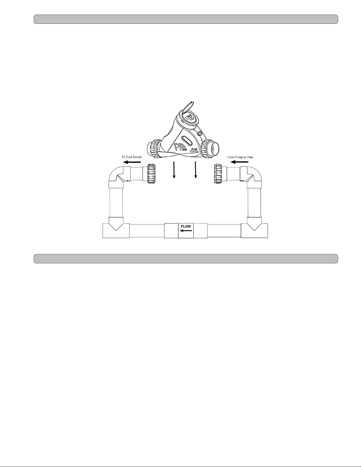
Flow Bypass Kit (Optional)
The ChlorSync®models are compatible with an optional flow bypass kit. The #STK0240
assembly allows the water flow rate to be slowed through the cell, while permitting the pump to
continue to circulate water to-and-from the pool/spa at full flow rates. The reduced water flow
through the cell results in a more efficient "Super-Chlorination” effect, resulting in improved
overall sanitization.
This bypass kit should be plumbed directly inline with the cell. See installation instructions in the
Installations Steps section of this manual.
ChlorSync®Flow Bypass Kit
Figure 3
Patented Temperature Compensation
The ChlorSync®uses the temperature sensor to determine water temperature. This
measurement is required for the temperature compensation feature to automatically adjust
chlorine output as water temperature varies.
The water temperature sensor works in conjunction with the purifier % feature to automatically
adjust chlorine output based upon changes in water temperature. Less chlorine is needed in
cold water, so chlorine output is automatically reduced as water temperature drops (avoiding
excess chlorine production). Conversely, more chlorine is needed in warmer water, and
production is automatically adjusted higher as water temperature increases.
As the water temperature falls below 65°F (18°C), the controller will automatically reduce the
purifier % and will reduce the maximum % that can be selected. This feature prevents the
controller from generating excessive chlorine in cold water where it is not needed and prevents
premature cell failure.
Note: The unit will display the original user specified setting.

Page - 8
CONTROL PANEL OVERVIEW
User Display
ChlorSync®Cell Label
Figure 4
Salt Indicator LED
The ChlorSync®checks the pool water salinity on start-up and every 12 hrs. thereafter and
displays the levels as follows:
lGreen LED (solid): Indicates salt level is adequate. Pool water salt level is between 2,700 ppm (mg/L)
and 4,500 ppm (mg/L).
lGreen LED (flashing): Salt level is above 5,000 ppm (mg/L). The unit is still producing chlorine and will
not be damaged by high salt conditions.
lRed LED (solid): The display shows ( LO SALT). The salt level is between 2,300 ppm (mg/L) and
2,700 ppm (mg/L). The unit will generate chlorine, but at a lower output level. See "Salt Addition
Information" on page 15. Add salt as needed.
lRed LED (flashing):The display shows (ADDSALT). The salt level is below 2,300 ppm (mg/L). The
unit will not generate chlorine until the minimum amount of salt has been reached. See "Salt Addition
Information" on page 15. Add salt as needed.
lNOTE: When salt is added, the circulation pump should be run continuously until the salt has been fully
dissolved. After the salt is dissolved, reset the power to the power supply. This will allow for accurate
measurement of the new salt level.
Cell Indicator LED
This light indicates the ChlorSync®cell status.
lGreen LED (solid): The unit is operating normally.
lRed (flashing):The unit is not producing chlorine. The cell will display the message (CELL) and
should be inspected. Conductivity may be reduced due to calcium buildup on the cell blades, low salt, etc.
Refer to the Troubleshooting section of this manual for more information.
Flow Indicator LED
This light indicates water flow through the ChlorSync®.
lGreen LED (solid): The flow sensor detects adequate water flow to produce chlorine.
lRed LED (flashing):The display shows (noFLo). The flow sensor detects low water flow through the
cell. The unit will not produce chlorine without water flow.

Page - 9
Cell Output Control
The ChlorSync®display will show the selected sanitizer output % and cell polarity during normal
operation. The △or▽buttons are used to adjust the sanitizer output % to the desired level.
When paired with the PoolSyncTM option, consult the PoolSyncTM app for more information.
To increase or decrease sanitizer output %:
1. Press the ▽button one time to decrease sanitizer output by 1%, or the △button one time to
increase output by 1%. Press and hold for 10% increments or decrements.
2. The current sanitizer output will begin to flash on the display. The sanitizer output can be adjusted at
this time.
3. Release the △or▽button when the desired sanitizer output is reached. The unit will resume
normal operation.
The rotating character shown on the left side of the display informs that the unit is generating
chlorine. If the rotating character is not present, the cell is not generating chlorine at that time but
will do so shortly.
lA clockwise motion denotes forward polarity on the blades and a counter-clockwise denotes reverse
polarity.
Rotating character shown clock-wise
Figure 5
Boost Mode On/Off
The Boost feature is used to increase the sanitizer output from its normal setting to 100% for a
cumulative 24 hour period of circulation pump run time. During this time, the sanitizer output
display will show "100%" as well as the hours remaining in the boost period. When the boost
period expires or is manually terminated, the sanitizer output % returns to its previous setting
and normal operation.
lPress the △or▽buttons simultaneously to turn Boost Mode on or off.
WATER BALANCE AND CHEMISTRY RECOMMENDATIONS
Water balance is the relationship between different chemical measurements in your pool water.
A pool that is balanced has proper levels of pH, Total Alkalinity and Calcium Hardness.
Balanced water can also be defined as water that is not corrosive or scaling. Water that is not
balanced can damage equipment and pool surfaces.
Proper water chemistry levels are essential to maintain safe and consistent swimming pool
operation. Sanitizers are used to destroy harmful or otherwise objectionable organisms.
Stabilizer or Cyanuric Acid (CYA) is used in many regions to reduce unnecessary loss of
chlorine to sunlight. Salt is used by the ChlorSync®to generate chlorine sanitizer.
Please note the following recommended water chemistry parameters are for residential pool/spa
applications only. Follow local regulatory guidelines for any commercial pool applications.

Page - 10
Table 1
POOL SPA
Parameter Units Min Ideal Max Min Ideal Max
Free Chlorine ppm (mg/L) 1.0 2.0 - 4.0 5 2.0 3.0 - 4.0 10
Combined Chlorine ppm (mg/L) 0.0 0.0 0.2 0.0 0.0 0.5
pH - 7.2 7.4 -7.6 7.8 7.2 7.4 -7.6 7.8
Total Alkalinity ppm (mg/L) 60 80 - 100 180 60 80 - 100 180
Calcium Hardness ppm (mg/L) 150 200 - 400 1,000 100 150 - 250 1,000
Salt ppm (mg/L) 2,300 3,500 - 4,500 ** 2,300 3,500 - 4,500 **
Cyanuric Acid (Stabilizer) ppm (mg/L) 0 30 - 50 *** 0 30 - 50 ***
** A salt level of 3,500 - 4,500 ppm (mg/L) is recommended.
*** This is dictated by state or local codes but is typically 80 ppm (mg/L).
Refer to "Basic Water Chemistry" and "Using the Saturation Index" sections in this manual for further
information concerning pool/spa water chemistry maintenance requirements.
See "Troubleshooting" on page 25 for assistance with resolving low or high chlorine issues.
Basic Water Chemistry
The ChlorSync®is designed to produce chlorine on a daily basis. To monitor the system’s
efficiency, the water chemistry ranges and a schedule of periodic checks should be followed.
See Table 2 on the following page for recommendations.
CAUTION - Failure to heed the following may result in equipment damage.
lExcessively high chlorine levels can cause premature cell depletion and corrosion damage to pool
fixtures and equipment.
lAlways turn the ChlorSync®unit off before adding chemicals to the pool/spa.
lNever use dry acid to adjust pH in arid geographic areas with excessive evaporation and minimal
dilution. A buildup of by-products can damage the cell.
lAlways follow the instructions on the manufacturer's label whenever handling or using chemicals.

Page - 11
Table 2
Chemical
Ideal
Test
Schedule
Effect of Low / High Levels Corrective Actions
Free
Chlorine Weekly
Low free chlorine: Not enough residual chlorine to
safely sanitize pool water.
Low free chlorine: Check for combined chlorine level
and shock as necessary. Increase chlorine output to
maintain a 2.0 - 4.0 ppm (mg/L) residual. Check
stabilizer level and add as necessary.
High free chlorine: Corrosive to metallic fixtures in
pool water. Can bleach swimwear and hair or
cause premature chlorinator cell depletion.
High free chlorine: Decrease chlorine output. Let
chlorine dissipate normally until 2.0 - 4.0 ppm (mg/L) is
achieved. In extreme cases, pool water can be diluted
with fresh water or a chlorine neutralizer added.
(Diluting will reduce salt and CYA. Check and adjust
as needed.)
pH Weekly
Low pH: (acidic) Equipment corrosion, eye/skin
irritation, plaster etching, rapid chlorine
consumption.
Low pH: Add sodium carbonate or soda ash.
High pH: (basic) Scale formation, cloudy water,
poor chlorine effectiveness, eye/skin irritation.
High pH: Add sulfuric acid, muriatic acid or sodium
bisulfate.
Total
Alkalinity Monthly
Low TA: Eye irritation, pH "bounce", stained, etched
plaster and metal corrosion. Low TA: Add sodium bicarbonate.
High TA: Constant acid demand, difficulty in
maintaining pH, and contributes to scale formation
or cloudy water conditions.
High TA: Add sulfuric acid, muriatic acid often or
sodium bisulfate more frequently until the TA is within
an acceptable range.
Calcium
Hardness Monthly
Low CH: Etching of the plaster, equipment
corrosion. Low CH: Add calcium chloride flakes.
High CH: Scale formation, cloudy water. Rapid
buildup of scale may exceed the system's self-
cleaning capability and require manual cleaning of
the cell.
High CH: Partially drain and refill pool with fresh water
to dilute. (Diluting will reduce salt and CYA. Check and
adjust as needed.)
Cyanuric
Acid
(Stabilizer
or CYA)
Monthly
Low CYA: Destruction of chlorine by the UV rays
from the sun.
Low CYA: Add cyanuric acid 1 lb. (0.45 kg) per 5,000
gallons (18,930 liters) increases CYA 25 ppm (mg/L).
High CYA: Requires more chlorine to maintain
proper sanitizer levels. Note: CYA is not needed for
indoor pools. CYA should be reduced to 30 - 50
ppm (mg/L) for colder climate regions.
High CYA: Partially drain and refill pool with fresh
water to dilute. (Diluting will reduce salt. Check and
adjust as needed.)
Saturation
Index Monthly
+ 0.3: Water is scale forming. Calcium carbonate is
falling out of solution. This rapid buildup of scale
may exceed the system's self-cleaning capability
and require manual cleaning of the cell.
Balance the pool/spa water as close to an equilibrium
of 0 as possible. See "Using the Saturation Index" on
page 14.
- 0.3: Water is corrosive. Water will take away other
material it comes in contact with to form a natural
balance. These materials can be metallic fixtures,
swimwear, etc. Results can also include cloudy
water, eye/skin irritation, and poor chlorine
effectiveness.
Balance the pool/spa water as close to an equilibrium
of 0 as possible. See "Using the Saturation Index" on
page 14.
Salt Monthly
Low Salt: Below 2,700 ppm (mg/L) causes
premature cell failure and reduces chlorine
production.
Low Salt: Add salt according to digital display on the
ChlorSync®unit or salt chart.
High Salt: Above 6,000 ppm (mg/L) can cause
corrosion of metallic fixtures and will taste salty.
High Salt: If undesirably high, partially drain and refill
the pool with fresh water. (Diluting will reduce CYA.
Check and adjust as needed.)

Page - 12
Chlorine
The desirable form of chlorine is called Free Chlorine. This form of chlorine is responsible for the
actual sanitation activity in pools and spas. Free chlorine is highly reactive and, once added to
pool/spa water, has a tendency to combine with organic matter in the pool/spa. It quickly attacks
pathogens as well as other bather wastes. When chlorine combines, it chemically changes. The
chlorine binds to organic matter and is referred to as Combined Chlorine. Combined chlorine is
responsible for eye burn and skin irritations. Total Chlorine is the sum of free chlorine and
combined chlorine. If a strong chlorine odor is noted, it is due to an excess of combined chlorine.
It is important to test the total chlorine as well as free chlorine. If there is a difference greater than
0.2 ppm (mg/L), a shock treatment should be initiated.
During peak chlorine demand (summer months, rainy season or heavy bather usage) it may be
necessary to increase your chlorine output by increasing your sanitizer output setting.
Conversely, during low chlorine demand, you can decrease your output to a lower setting. For
extremely heavy chlorine demand or to boost your chlorine residual levels quickly, you can
supplement with any type of chlorine or non-chlorine shock containing potassium
monopersulfate. Avoid using excess amounts of treatments containing sodium bromide.
Note: During cold-water conditions (below 60ºF (15.6ºC)) chlorine demand is reduced
significantly. For colder climate regions with sustained low temperatures, contact your local pool
professional for proper pool winterizing instructions.
pH
pH is a term used to refer to the degree of activity of an acid or base in the water. A low pH,
acidic or corrosive water, contributes to eye and skin irritation as well as damage to pool
equipment. A high pH will result in scaling, cloudy water and ineffective sanitation. Improper pH
also contributes to the strong smell, red eyes and dry itchy skin conditions that are usually
blamed on “too much chlorine” being in the pool/spa.
Total Alkalinity
Total Alkalinity refers to the ability of the pool water to resist a change in pH. It helps manage or
control the pH in the pool. The desired range is 80 to 100 ppm (mg/L). Low alkalinity is
aggressive or corrosive and causes the pH readings to fluctuate (pH bounce). High alkalinity
may cause cloudy water and scale forming conditions. Your chlorinator does not affect total
alkalinity. Factors changing this measure are ancillary chemicals added to the pool and “out of
balance” make-up water.
Calcium Hardness
Calcium Hardness is a measure of calcium content in the water. If the calcium content is too
high, calcium can drop out of solution; forming scale on equipment. A low level will cause the
water to become corrosive as the water tries to naturally form equilibrium. This means the water
will “leach” minerals from everything it meets. Damage to equipment and unpleasant swimming
conditions result. Your chlorinator does not change calcium hardness. Factors changing this
measure are ancillary chemicals added to the pool and “out of balance” make-up water.
Page - 13
Cyanuric Acid
Cyanuric Acid acts as water “Stabilizer” or “Conditioner”. This chemical goes by either trade
name and allows your chlorine residual to last longer by protecting it from the UV rays of the sun.
With low cyanuric acid, chlorine can be used up just as quickly as it is generated.
Note: For indoor pools, it is not necessary to maintain a stabilizer level to protect the chlorine
from the UV rays.
Metals
Some metals, i.e. copper and iron, can cause loss of chlorine. Also, metals can stain your pool.
Have your local pool professional check for metals and recommend methods of removal. Metal
content should be 0 ppm (mg/L).
Preparing the Pool Water
Installer please note - When properly sized to the site, the AutoPilot®will meet the sanitizer
“maintenance” requirements of the pool/spa. The unit is not designed to chlorine shock treat or
build up a chlorine residual when starting with a zero or very low chlorine level.
Before starting the chlorinator, the water must be properly balanced, and the chlorine level
adjusted to between 2.0 - 4.0 ppm (mg/L) free chlorine. See more on adjusting water balance
and start-up chlorine levels earlier in this section.
Calculating Pool Volume
To determine the approximate number of gallons or liters in a pool or spa:
1. Determine the surface area.
2. Multiply the surface area by the average depth and the constant conversion factor of 7.5 to convert
cubic feet to gallons, or 1,000 to convert from cubic meters to liters.
Rectangle
lArea = Length x Width
lGallons = area x average depth (ft3) x 7.5
lLiters = area x average depth (m3) x 1,000
Circular
lArea = Radius x Radius x 3.14
lGallons = area x average depth (ft3) x 7.5
lLiters = area x average depth (m3) x 1,000
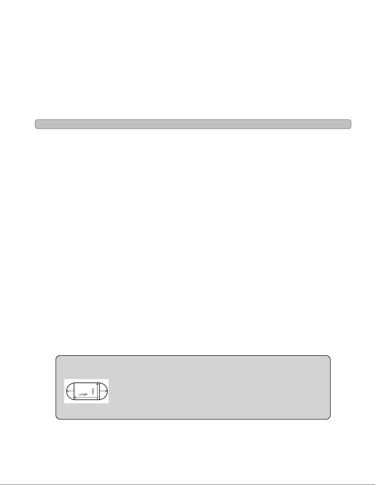
To determine the approximate number of gallons or liters in a more complex shaped pool:
1. Divide the complex shape into several simple shapes.
2. Calculate each one separately, and then add back together.
Example: An oblong pool can be divided into two radius measurements and one
rectangular shape. (R = Radius)
lArea = Radius x Radius x 3.14 + (Length x Width)
lGallons = area x average depth (ft3) x 7.5
lLiters = area x average depth (m3) x 1,000
Page - 14
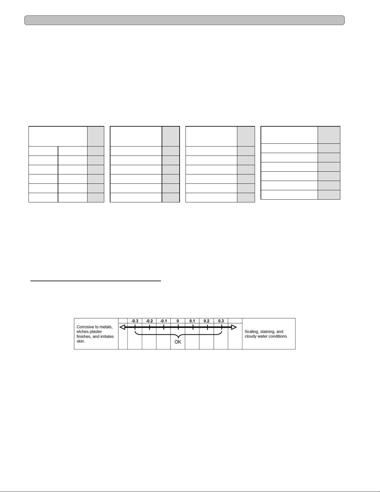
Using the Saturation Index
This index is used by pool professionals to ensure that your total water chemistry does not fall
into a corrosive or scaling condition. Either condition can cause premature damage to the cell,
any of your other equipment, as well as your cementitious finish.
The Saturation Index is composed of the following factors:
lpH as tested
lPlus the Temperature factor
lPlus the Calcium Hardness factor
lPlus the Alkalinity factor
lMinus the Total Dissolved Solids factor (in this case the bulk of the dissolved solids are salt)
This is expressed in the formula SI = pH + TF + CF + AF – TDSF and uses the following charts:
TEMPERATURE TF
60°F 15.6°C 0.4
66°F 18.9°C 0.5
76°F 24.4°C 0.6
84°F 28.9°C 0.7
94°F 34.4°C 0.8
103°F 39.4°C 0.9
CALCIUM
HARDNESS CF
150 ppm (mg/L) 1.8
200 ppm (mg/L) 1.9
250 ppm (mg/L) 2.0
300 ppm (mg/L) 2.1
400 ppm (mg/L) 2.2
600 ppm (mg/L) 2.4
TOTAL
ALKALINITY AF
075 ppm (mg/L) 1.9
100 ppm (mg/L) 2.0
125 ppm (mg/L) 2.1
150 ppm (mg/L) 2.2
200 ppm (mg/L) 2.3
250 ppm (mg/L) 2.4
SALT LEVEL TDSF
0000 - 1000 ppm (mg/L) 12.1
1001 - 2000 ppm (mg/L) 12.2
2001 - 3000 ppm (mg/L) 12.3
3001 - 4000 ppm (mg/L) 12.4
4001 - 5000 ppm (mg/L) 12.5
5001 - 6000 ppm (mg/L) 12.6
Example:
7.8 = pH as measured
0.7 = Temperature is 84°F (TF)
2.4 = Calcium Hardness is 600 ppm (mg/L) (CF)
2.3 = Total Alkalinity is 200 ppm (mg/L) (AF)
12.4 = Salt is 3,500 ppm (mg/L) (TDSF)
0.8 = Saturation Index.
This water is scale forming and needs to be balanced.
Table 3
If adjustments need to be made to balance the water, the recommended sequence is as follows:
1. Test and adjust total alkalinity. This may reduce pH so wait at least 8 hours before proceeding.
2. Test again and adjust pH, then
3. Adjust calcium hardness.

Page - 15
Adding Salt
Type of Salt to Add
It is important to use Sodium Chloride (NaCl) salt that is greater than 99% pure. Acceptable
types of salt include granular food grade, pool salt, water softener pellets, or solar salt flakes.
Pool salt or food grade granular salt will dissolve faster than pellets or flakes. Rock salt and
Granular Salt with Iodine or Rust Preventatives should not be used, as these mixtures contain
high levels of impurities that may cause staining. Granular salts containing anti-caking additives
such as YPS (Yellow Prussiate of Soda) or sodium ferrocyanide are not recommended as they
can cause a localized tint to the water or yellow staining of the pool/spa finish.
Amount of Salt Required
Test the water for current salt content first!
The ideal salt range is 3,500 – 4,500 ppm (mg/L). The minimum salt level is 2,300 ppm (mg/L).
Salt levels above 6,000 ppm (mg/L) are not normally recommended, as corrosion issues may
result. Salt levels below 3,500 ppm (mg/L) will reduce the efficiency of the ChlorSync®and will
result in low chlorine production. Extremely low salt levels below 2,300 ppm (mg/L) will activate
the low salt safety cut off and will halt chlorine production until salt is replenished to proper
levels.
For information on amount of salt to be added relative to the volume of water to be treated vs.
existing salt level, refer to the salt addition information in the section below.
How to Add Salt to Pool
CAUTION - Failure to heed the following may result in equipment damage.
lFor newly plastered pools, do not operate the ChlorSync®SCG for 30 days after construction is
completed. You must allow the plaster to cure, otherwise the salt could damage the pool finish.
lDo not allow salt to pile up in one location without brushing, as staining may occur.
The circulation pump should be run continuously until the salt has been fully dissolved. Add salt
directly to pool (or spa, if a spa-only installation) and over the main drain (if main drain is
present). If there is no main drain, a vacuum head may be used to encourage salt circulation.
Distributing the salt by brushing is also helpful; brush the salt toward the main drain (if one is
present). Set pump operation to normal run time after salt has fully dissolved into water.
If the salt level becomes undesirably high, the only way to remove excess salt is to partially drain
the pool/spa and refill with fresh water.
Salt Addition Information
The salt in the pool is constantly recycled during normal operation. Loss of salt during a
swimming season should be minimal. Filter back washing, draining due to rain water overflow,
splashing, bathing suit drag out, and leaks are typical ways salt is lost. Salt does not leave the
pool when water evaporates.
1. Determine pool/spa volume in Gallons or Liters.
2. Determine the current salt level in the pool. Some pools may already have a salt residual, so always
test water before adding salt. (This can be obtained from the control display or by testing water.)
3. Add salt as per the following formula:
lNew pool: 50 lbs (22.7 kg) of salt per 2,000 gallons (7,571 Liters) will raise the salt level by
3,000 ppm (mg/L).
lExample: For a 10,000 gallon (37,854 Liter) pool with a salt level of 500 ppm (mg/L), you
would need to add 250 lbs. (113.4 kg) of salt to bring the level up to 3,500 ppm (mg/L).

Page - 16
OPERATION
Basic Operation
Note: Upon initial start-up, check sanitizer every 3 - 4 days and make small
output level adjustments as necessary to maintain 2.0 - 4.0 ppm (mg/L) free
chlorine levels. Keep in mind, your chlorinator does not directly measure or
regulate the sanitizer levels in your pool. Rather, the owner/operator will need to
periodically test the water to determine the current chlorine level, and adjust the
output setting as needed.
This section is a brief explanation of the start up procedure and operating instructions for
chlorinator.
After construction is completed and the pool has been filled with water, wait 30 days before
adding salt and operating the chlorinator. The salt level should be maintained between 3,500 -
4,500 ppm (mg/L).
When sized properly to the specific body of water and site conditions, the chlorinator is designed
to generate daily, an adequate amount of sanitizer to maintain the recommended 2.0 - 4.0 ppm
(mg/L) of free chlorine.
With a properly balanced pool that has been pretreated to 2.0 - 4.0 ppm (mg/L) of chlorine, the
recommended sanitizer output setting starting point is 50% at start-up of the new system. The
sanitizer output % setting refers to the amount of time the cell is energized. The system cycles
on-and-off, as indicated by a rotating character on the display.
Use the △or▽buttons to adjust the sanitizer output percentage to the desired level from 0%
to 100%. See "Cell Output Control " on page 9 for more information.
If Using a Pool Pump Timer
The use of an external pool pump timer is not required.
The water circulation pump must be operating for your ChlorSync®to produce chlorine, so run
time is one of several key factors to maintaining proper sanitizer levels. Most installations require
a minimum of eight (8) hours-per-day pump run time to properly filter and sanitize the water.
The Pool and Hot Tub Alliance (PHTA) recommends that all water in a residential pool pass
through the filtration system at least once every six (6) hours, four (4) turns every 24 hours
(referred to as pool water turnover). However, the optimum output setting will vary based upon
pool size, location, exposure to sunlight, number of users, vegetation around the pool, water
balance practices, temperature and pump run time. Your installer should have already taken
these factors into consideration when performing installation programming.
Your pool pump should be set to run as per your pool professional recommendations to achieve
proper filtration and optimal chlorine production by your ChlorSync®chlorinator.
Note: At 55°F (13°C) or colder water temperatures, the controller will adjust to a fixed 1% output,
thus preventing over-chlorination and premature cell failure.
This manual suits for next models
2
Table of contents
Other Autopilot Lighting Equipment manuals


