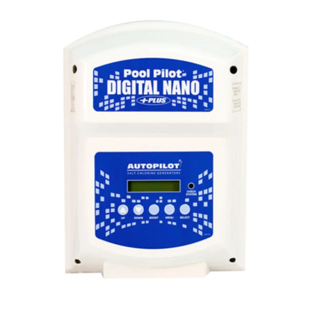
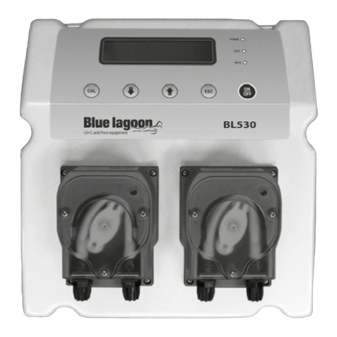
Autopilot POOL PILOT SOFT TOUCH User manual

1/17/03
1
POOL PILOT SOFT TOUCH OPERATING,
TROUBLESHOOTING AND TECHNICAL CHEAT SHEET
NORMAL OPERATING MODE OF SOFT TOUCH
1. Output Lights will pulsate to indicate Chlorine production.
a. There are 7 lights to indicate output level.
b. Chlorine Production is based upon an on/off period of a 30-minute cycle.
c. If lights are solid Green this means unit is in rest mode.
d. To increase percentage of chlorine production, press UP ARROW
e. To decrease percentage of chlorine production, press DOWN ARROW
(The lights will display between 1 light up to 7 lights to reflect output level)
2. Flow Light will be Green
a. If Flow light is not on see troubleshooting section.
3. Salt Light will be Green (OK)– unit will produce chlorine
4. If Salt light is Yellow (LOW) add salt until Green Salt light comes on or check with Salt
addition chart for proper amount
i. The Yellow Salt light comes on at 2500 ppm and unit will still produce chlorine.
5. If Salt light is Red (ADD)---unit will engage safety cell shut off. Unit will automatically
resume operation when salt is added back to sufficient levels.
i. The Red Salt light comes on below 2000 ppm of salt.
6. Pushing the BOOST BUTTON will increase chlorine production to 100% for 24 hours of
accumulative pump run time. The GREEN BOOST LIGHT will stay Solid Green
a. Holding the Boost Button down from Boost OFF mode for 8 seconds will increase the
Boost Cycle to 72 hours of accumulative pump run time. The Green Boost light will
flash
b. After Boost Cycle is complete the unit automatically reverts to the original Setting
c. Depress the Boost button in either Boost mode to deactivate Boost mode.
.

1/17/03
2
SOFT TOUCH TROUBLESHOOTING
**If the service light comes on, count the number of flashes and see below
?? 1 RED FLASH = LOW FLOW OR NO FLOW
The flow light will go out and the Service light will flash once
oVerify the that the filter is clean
?? If filter is dirty, clean the filter to increase the overall flow.
oVerify the water exiting the filter is not being diverted away from the inlet of the manifold.
?? Make sure they do not have valves closed off or water being diverted away to other
water features like waterfalls, therapy jets, etc. If they are diverting water away to
a water feature, they may have to adjust the valve so more flow goes through the tri
sensor to activate the flow. REMINDER: you need at least 15 GPM going through
the flow switch to activate it.
oVerify that the Manifold Strainer Screen is Clean
?? The strainer screen is located in the bottom portion of the manifold on the inlet
side.
?? Even if the screen appears clean, run the pump for a few seconds to flush any
debris that may have fallen back into the pipes.
oThe Tri Sensor may have Failed
?? Check Tri Sensor Flow switch for continuity
?? See Diagram “4A”
oTri Cable may have Failed
?? Check Tri Sensor Cable for Continuity
?? Use a multi motion for continuity check
?? 2 RED FLASHES –Low Amps with Salt OK
oCell may be Scaled
?? If cell is dirty, put cell in bucket with 1 part muriatic acid to 4 parts water for 15-
minute intervals until scale is completely removed. HINT: VERIFY
CHEMISTRY TO DETERMINE WHY CELL SCALED.
?? If cell scales within a week, unit may not be reversing polarity.
?? If cell scales 2 weeks or longer, water is unbalanced.
o20 amp fuse blown
oreplace 20 amp fuse
oVerify that unit is grounded correctly
oOn the PS at J3 location verify you have 12 to 12 ½ dc volts.
?? If you do not BAD POWER SUPPLY

1/17/03
3
SOFT TOUCH TROUBLESHOOTING CONT’D
**If the service light comes on, count the number of flashes and see below.
?? 3 RED FLASHES – very low amps with Salt OK
oV1.4 or older -scaled cell or failed cell
oPower Supply may have failed or improperly wired.
?? Check the Power Supply for Output. If you do not get a Volt reading the power
supply is bad
How to test: The Power Supply has built in diagnostic test (See page 13 of your manual for procedures),
or use a 957B tester, put tester in Power Supply mode or a Multimeter and test for Volts.
?? Verify unit and incoming voltage match.
oCell cord may have failed
?? Check Cell cord for Continuity
How to test: Use a Multi Meter and test for continuity. Center hole is the black wire.
oCell Failure
?? If you get High Volts and LowAmps your cell is bad.
How to test: The Power Supply has built in diagnostic test (See page 13 of your manual for procedures),
or use a 957B tester, put tester in Cell mode and test for volts and amps.
?? 4 RED FLASHES – Bad Temperature Sensor (salt will not be temperature compensated)
oReplace Tri Sensor

1/17/03
4
SOFT TOUCH TECHNICAL SPECIFICATIONS
MAXIMUM CELL CURRENT (DC AMPS) SOFT REVERSAL
Cell Power 1 = 5 AMPS Chlorine Production Stops 30 seconds before
Cell Power 2 = 6.5 AMPS reversing polarity.
Cell Power 3 = 8 AMPS
WARNING: Operating on level “1” reduces cell power but extends cell life, operating on level “3” increases cell
power but shortens cell life
REVERSAL TIME BOOST CYCLES
SHORT = Every 2 hours of cell run time Solid Green light is 24 hour boost
NORM = Every 4 hours of cell run time Flashing Green light is 72 hour boost
LONG = Every 8 hours of cell run time (Hold boost down for 8 seconds to get 72 hour boost)
NOTE: REVERSING AND BOOST CYCLE TIMES ARE STORED WHEN POWER GOES OFF, RESTARTING AT THE
SAME POINT IN THEIR CYCLE.
AUTOMATIC TEMPERATURE COMPENSATION
This feature automatically adjusts the output level setting based upon the changes in seasonal water
temperatures only. This unique feature conveniently compensates for warm (more purified needed) or
cold (less purified needed) water conditions.
*Remember that the output level is a time cycle based upon a 30-minute cycle. At 0% output, it is
generating 0 of 30 minutes. At 25%, it is generating 7.5/30 minutes. At 50%, it is generating 15/30
minutes. At 75% it is generating 22.5/30 minutes. And at 100% it is generating 30/30 minutes.
Temperature Output adjustment
50?F1% fixed setting
55?F25% of 70F setting
60?F50%
65?F75%
70?F100%
75?F125%
80?F150%
85?F175%
90?F200%
This is easier explained with the output level at 50% setting. At 70F, a 50% setting is truly 50%, thus
generating 15/30 minutes.
As the temperature increases to 80F, the 50% setting will still display as 50% but will continue to pulsate
(generate) 22.5/30 minutes due to the temperature compensation of 150%. 15 minutes x 150% = 22.5
minutes.
As the temperature increases to 90F or higher, the 50% setting will display 50% but will continue to
pulsate continually, 30/30 minutes. 15 minutes x 200% = 30 minutes.
As the temperature decreases to 65F, the unit will pulsate 11.25/30 minutes. 15 minutes x 75% = 11.25
minutes.
As the temperature decreases to 60F, the unit will pulsate 7.5/30 minutes. 15 minutes x 50% = 7.5
minutes.
As the temperature decreases to 50F or lower, the unit will pulsate 18 seconds/30 minutes, 30 x 1% =0.30
minute (18 seconds)
(**This is true for all output settings at 50F or lower)

1/17/03
5
DIAGRAM “4A”
TRI-SENSOR CABLE / WIRING DIAGRAM
RED 1 Flow
FLOW
WHITE 2
5 1
BROWN 3 Salt
6 SALT
GREEN 4
4 2
BLACK 5 Temp
3 BLUE 6
TEMP.
TRI-SENSOR CABLE PLUG
(FEMALE CONNECTIONS)
FLOW
DETECTOR
1 5
TEMP
6 SENSOR
2 4
SALT
3 SENSOR
TRI-SENSOR ASSEMBLY HEAD PLUG
(MALE CONNECTIONS)
NOTE (Perform these tests on the Tri-Sensor Assembly):
-Test for continuity of the FLOW pins by attaching a continuity meter test leads to pins #1 & #2 and
manually activating the flow paddle to the center post.
-Test for continuity of the SALT pins by attaching a continuity meter test leads to pin #3 and the INSIDE
of either of the two the salt blades. Perform same test on pin #4 and the opposite blade.

1/17/03
6
Table of contents
Other Autopilot Lighting Equipment manuals
Popular Lighting Equipment manuals by other brands
Karma
Karma TM WASH60LS instruction manual
Trilux
Trilux LUCEOS S ETDD Series Assembly instructions
CHINT
CHINT ND16 Series User instruction

Sealey
Sealey ML36110T instruction manual
Source
Source SFES10M installation instructions
Federal Signal Corporation
Federal Signal Corporation Signalmaster 330103 instruction sheet
