manuals.online logo
Brands
  1. Home
  2. •
  3. Brands
  4. •
  5. WE-EF
  6. •
  7. Lighting Equipment
  8. •
  9. WE-EF DAC200 LED Series User manual

WE-EF DAC200 LED Series User manual

WE-EF LIGHTING Thailand
Tel +66 2 738 9610
info.asiapacific@we-ef.com
WE-EF LIGHTING USA
Tel +1 724 742 0030
info.usa@we-ef.com
WE-EF LEUCHTEN Germany
Tel +49 5194 909 0
info.germany@we-ef.com
WE-EF LUMIERE France
Tel +33 4 74 99 14 44
info.france@we-ef.com
WE-EF LIGHTING Australia
Tel +61 3 8587 0444
info.australia@we-ef.com
WE-EF HELVETICA Switzerland
Tel +41 22 752 49 94
info.switzerland@we-ef.com
www.we-ef.com
DAC200_LED_010220 / 006-1622
Données techniques susceptibles de changer.
Technical specifications are subject to change.
© WE-EF 2020
Sécurité
Le fabricant décline toute responsabilité résultant d'une mise en
oeuvre ou d'une installation inappropriée du produit.
Toutes les modifications apportées à ce luminaire et/ou cet
accessoire se feront sous la responsabilité exclusive de celui qui
les effectuera.
Safety indices
The manufacturer is then discharged from liability when damage is
caused by improper use or installation.
If any luminaire and/or accessory is subsequently modified, the
persons responsible for the modification shall be considered as
manufacturer.
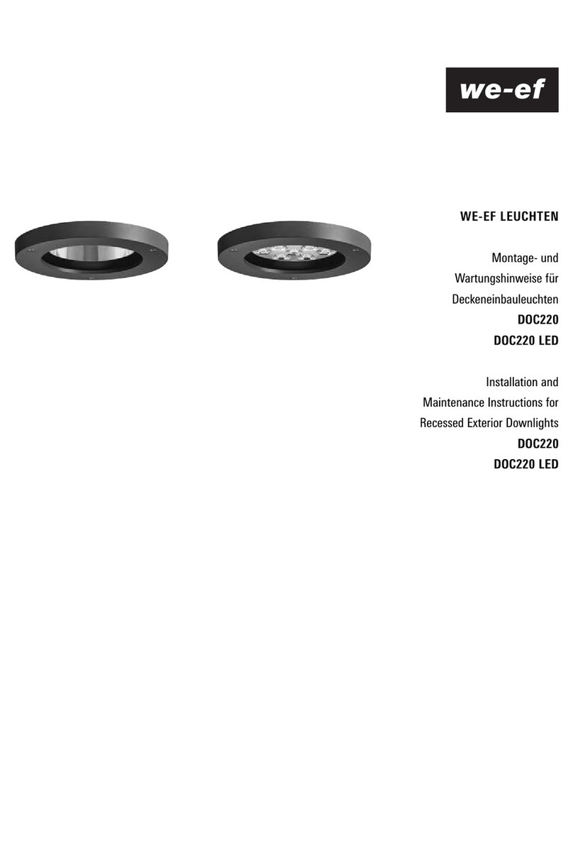
WE-EF LEUCHTEN
Instructions d’installation et
de maintenance pour
Downlights
Série DAC200 LED
Installation and
Maintenance Instructions for
Surface mounted exterior downlights
DAC200 LED Series
Zone d’entrée de câble Area of cable entry
ø 154
176
75
85
ø 5
237
ø 250
120
140
ø 6
267
355°
0°-30°
ø 250
120
140
ø 6
ø 100
ø 160
ø 160
Surface Mounted Exterior Downlights
IP65, IK07
Downlights
IP65, IK07
Outils nécessaires
– Tournevis cruciforme Philips T. 2
– Tournevis plat 3,0 mm x 0,8 mm
– Tournevis TX 25
– Clé Allen 4 mm
– Clé plate 24 mm / 22 mm
Tools required
– Screwdriver recessed head size 2 Philips
– Screwdriver with 3.0 mm x 0.8 mm blade
– Screwdriver TX 25
– 4 mm Allen key
– open-ended spanner 24 mm / 22 mm
Source / Light source
DAC220 . . . . . . . . . . . . . . . . . . . . . . . . . . .12 LED 24W*
DAC240 . . . . . . . . . . . . . . . . . . . . . . . . . . .24 LED 48W*
DAC240-GB . . . . . . . . . . . . . . . . . . . . . . . .12 LED 18W*
* Pour la puissance nominale, les données actualisées,
voir www.we-ef.com
* Nominal power, for latest data refer to www.we-ef.com
DAC220 DAC240
DAC240-GB
Classe / Class I, ta = 25°C
Poids / Weight: . . . . .DAC220 . . . . . . . . . . . . . . . 2,9 kg
. . . . . . . . . . . . . . . . . .DAC240 . . . . . . . . . . . . . . . 7,6 kg
. . . . . . . . . . . . . . . . . .DAC240-GB . . . . . . . . . . . . 8,5 kg
ø 5,5 - 12 mm 2,5 mm2
Installation
The product must be installed and maintained by a suitably
qualified professional in compliance with latest building/
construction and/or electrical regulations and relevant
legislation.
Notice: If the luminaire is modified by anybody other than
the original manufacturer, then the warranty will no longer
be valid and shall become the full responsibility of the
modifying person/organisation. Claims based on defects
attributable to improper installation and/or application, and
the consequences thereof, are excluded.
In case of component failure, LED replacement due to
abnormal circumstances or at end of life, replacement
must be carried out by a suitably qualified and trained
professional.
In case of questions please contact our technical hotline:
+49 5194 909209 (from Monday - Friday from 08.00 until
16.00 hours.
Maintenance
Apart from cleaning the product’s exterior surfaces, no
special maintenance work is required. Do not use high-
pressure cleaners.
Protect our environment: Discard used LEDs in compliance
with the most recent environmental legislation.
Installation
L’installation et l’entretien ne doivent être effectués que
par du personnel spécialisé disposant d’une qualification
professionnelle adéquate, conformément aux dernières
prescriptions d’installation et de sécurité électriques.
Recommandation : Les modifications du luminaire qui ne
sont pas effectuées par le fabricant d’origine entraînent
l’annulation de la garantie du fabricant d’origine et le
transfert total des obligations en découlant sur la personne/
organisation à l’origine de la modification. Sont exclues
toutes réclamations concernant des défauts reliés directe-
ment ou indirectement à un montage et/ou une utilisation
non conformes.
En cas de panne de composants dues à des circonstances
inhabituelles ou à la fin de la durée de vie, le remplace-
ment ne doit être effectué que par du personnel spécialisé
présentant une qualification professionnelle adéquate.
En cas de questions, veuillez vous adresser à notre hotline
technique au +49 5194 909209 (lundi - vendredi de 08h00
à 16h00).
Maintenance
Outre le nettoyage de l’extérieur du produit, aucune main-
tenance particulière n’est nécessaire. Ne pas utiliser de
nettoyeur haute pression.
Pour l’élimination des LED, les lois environnementales
actuellement en vigueur doivent être respectées.
D
A
C
B
F
E
Installation Procedure
1) Switch off the mains electrical supply.
2) Loosen screws Aand remove mounting pot B. Detach
male side from terminal connector E.
3) Set mounting pot Bin position and fix it to the ceiling
by means of two screws C.
Caution: Make sure not to damage any electrical cable,
water pipe or other devices while drilling holes
4) Feed mains cable through cable gland F. Connect the
mains supply leads to their respective terminals in the
terminal connector E(N = neutral, L1 = phase, =
earthing).
5) Tighten cable gland Ffirmly.
6) Match male to female side of terminal connector
E.Position luminaire body Dover mounting pot B.
Firmly tighten the threaded pins A.
Procédure
1) Garantir l’absence de tension du cordon d’alimentation.
2) Dévisser les tiges filetées A, tirer le pot de montage B
vers le haut et débrancher le connecteur E.
3) Préparer la surface de fixation et fixer le pot de monta-
ge Bavec la visserie Cfournie.
Attention : S’assurer de n’endommager aucun câble
électrique, aucune conduite d’eau ni aucun autre appa-
reil pendant le perçage.
4) Faire passer le cordon d’alimentation à travers le rac-
cord vissé F. Raccorder le conducteur neutre (N), la
phase (L1) et le conducteur de protection sur les
contacts du connecteur prévus à cet effet et marqués
en conséquence.
5) Serrer fermement le raccord de câble F.
6) Brancher le connecteur E, pousser le boîtier de luminai-
re Dsur le pot de montage Bet tendre le tout avec les
tiges filetées A.
E
D
C
B
A
F
Achtung:
Bei Verwendung einer Streulinse ist die Lichtrichtung zu
beachten. Die Linse muss mit der strukturierten Seite zu
den LEDs eingesetzt werden!
DAC220
Bei Verwendung einer Streulinse IO-20 ist die Lichtrichtung
Eund Montageposition Fzu beachten!
A= Rahmen
B= Abdeckung
C= Streulinse (IO-20, IO-180 oder I0-360)
D= Dichtung
E= Lichtrichtung
F = Montageposition
Important:
In applications using lenses, make sure the light is orienta-
ted in the direction of the object to be lit. Please ensure
that the prismatic side of the lens is facing the LEDs.
DAC220
When using a IO-20 lens, the light direction Eand moun-
ting position Fmust be observed!
A= Frame
B= Cover
C= Lens (IO-20, IO-180 or I0-360)
D= Gasket
E= Direction of light
F = Installation position
Attention :
En cas d’utilisation d’un diffuseur, faire attention à la direc-
tion de la lumière. La lentille doit être installée avec la par-
tie structurée dirigée vers les LED !
DAC220
En cas d’utilisation d’un diffuseur IO-20, faire attention à la
direction de la lumière E et à la position de montage F!
A= cadre
B= lentille
C= diffuseur (IO-20, IO-180 ou I0-360)
D= joint
E= direction de la lumière
F = position de montage
Important:
In applications using lenses, make sure the light is orienta-
ted in the direction of the object to be lit. Please ensure
that the prismatic side of the lens is facing the LEDs.
DAC220
When using a IO-20 lens, the light direction Eand moun-
ting position Fmust be observed!
A= Frame
B= Cover
C= Lens (IO-20, IO-180 or I0-360)
D= Gasket
E= Direction of light
F = Installation position
Version avec Gimbal
Sur la version avec Gimbal, la zone LED peut être tournée
sur 355° et pivotée sur 30°.
Rotation : Dévisser la visserie Ipermet de tourner le
Gimbal sur 355°. Pour faciliter la rotation, un outil peut être
utilisé dans les cavités G.
Pivotement : Dévisser la visserie Hpermet de pivoter le
Gimbal sur 30°. Serrer ensuite de nouveau la visserie H.
Tilt: By loosening of the screws Hthe Gimbal is tiltable by
30°. Afterwards firmly tighten the screws Hagain.
Rotate: By loosening of the screws Ithe Gimbal is rotat-
able by 355°. To make the rotating easier it is possible to
use a tool inside the recess G.
Gimbal Version
With the Gimbal version the LED area is rotatable by 355°
and tiltable by 30°.
H
G
I

Other WE-EF Lighting Equipment manuals

WE-EF DOC220 User manual

WE-EF

WE-EF DOC220 User manual

WE-EF ETC329-FS LED User manual

WE-EF

WE-EF ETC329-FS LED User manual

WE-EF KTX234 User manual

WE-EF

WE-EF KTX234 User manual

WE-EF XRY300 LED Series User manual

WE-EF

WE-EF XRY300 LED Series User manual

WE-EF RMT320 LED User manual

WE-EF

WE-EF RMT320 LED User manual

WE-EF FLC100 Series User manual

WE-EF

WE-EF FLC100 Series User manual

WE-EF CFT500 LED Series User manual

WE-EF

WE-EF CFT500 LED Series User manual

WE-EF VLR100 LED Series User manual

WE-EF

WE-EF VLR100 LED Series User manual

WE-EF LTM440 User manual

WE-EF

WE-EF LTM440 User manual

WE-EF QLS410 LED User manual

WE-EF

WE-EF QLS410 LED User manual

WE-EF LGI440 User manual

WE-EF

WE-EF LGI440 User manual

WE-EF GTY200 LED Series User manual

WE-EF

WE-EF GTY200 LED Series User manual

WE-EF LSP400 LED Series User manual

WE-EF

WE-EF LSP400 LED Series User manual

WE-EF QSI254 User manual

WE-EF

WE-EF QSI254 User manual

WE-EF VFL540-SE LED User manual

WE-EF

WE-EF VFL540-SE LED User manual

WE-EF RFS500 Series User manual

WE-EF

WE-EF RFS500 Series User manual

WE-EF FLC121 User manual

WE-EF

WE-EF FLC121 User manual

WE-EF FLC122LED User manual

WE-EF

WE-EF FLC122LED User manual

WE-EF ESC330-FS LED User manual

WE-EF

WE-EF ESC330-FS LED User manual

WE-EF RAIL66 Series User manual

WE-EF

WE-EF RAIL66 Series User manual

Popular Lighting Equipment manuals by other brands

LIFE home integration SUNLED 23 manual

LIFE home integration

LIFE home integration SUNLED 23 manual

Chauvet Ovation F-145WW user manual

Chauvet

Chauvet Ovation F-145WW user manual

Clas Ohlson WX-C-LED44-12WW-1 instruction manual

Clas Ohlson

Clas Ohlson WX-C-LED44-12WW-1 instruction manual

spanninga S-RUN quick start guide

spanninga

spanninga S-RUN quick start guide

Robe Robin T2 user manual

Robe

Robe Robin T2 user manual

Newskill MYTHOS quick guide

Newskill

Newskill MYTHOS quick guide

THELIGHT 4LIGHT user manual

THELIGHT

THELIGHT 4LIGHT user manual

Bresser BR-F36B instruction manual

Bresser

Bresser BR-F36B instruction manual

Interfit F121 user manual

Interfit

Interfit F121 user manual

LUXO Circus Instructions for use

LUXO

LUXO Circus Instructions for use

ADJ Revo sweep User instructions

ADJ

ADJ Revo sweep User instructions

Rollei LUMIS Key Light Pro manual

Rollei

Rollei LUMIS Key Light Pro manual

DÖRR EcoLine II 110 Ws instruction manual

DÖRR

DÖRR EcoLine II 110 Ws instruction manual

Velleman HQ POWER HQPE10010 user manual

Velleman

Velleman HQ POWER HQPE10010 user manual

UFO MICROLED 2000 user guide

UFO

UFO MICROLED 2000 user guide

DSE NOVA user manual

DSE

DSE NOVA user manual

thomann Varytec BAT.PAR 6 RGBWA user manual

thomann

thomann Varytec BAT.PAR 6 RGBWA user manual

High End Systems x.Spot user manual

High End Systems

High End Systems x.Spot user manual

manuals.online logo
manuals.online logoBrands
  • About & Mission
  • Contact us
  • Privacy Policy
  • Terms and Conditions

Copyright 2025 Manuals.Online. All Rights Reserved.