Pledco VFI6 User manual

Pledco Broadcast Indoor
User ' s Manual
Version 1.1
Pledco LED Display Ltd.

a
a
A Broadcast Indoor
A Broadcast Indoor
Broadcast Indoor
1
TableofContents
1.Safety
1.1Guidelines
1.2Safetyinstructions
2.SeriesTiles
2.1Tile
2.2display
3.Installation requirements
3.1Mechanicalrequirements
3.2Electricalrequirements
3.3Systemrequirementsforthe Controlsoftware
4.Componentsofdisplay
4.1Tile
4.2MechanicalComponents
4.3PowerSupplyUnit
4.4LDU
4.5Video ProcessingUnit
4.6Cables
4.7Controlsoftware
4.8Others
5.Installation
5.1Preparingthe back supportingstructure
5.2Mountingthe extrusionframe
5.2.1Assemblingthe extrusion frame
5.2.2Mountingtheframe
5.3Fixingthe display
5.4Othermountingmethods
6. Cabling display
6.1Cablingan on-line display
6.2Cablingan off-line display
6.3Pixellimitations
7.Maintenance
7.1Firmwareupdate
7.1.1LDU firmwareupdate
7.1.2Tilecontrolboardfirmwareupdate
7.2ReplacingaTileofdisplay
7.3ReplacingaTileofafront serviced display
7.4ReplacingaTilecontrolboard
7.5Replacingapowersupply
7.6ReplacingaLDU controlboard
8.Troubleshooting
9. Specifications
9.1VFI seriesdisplayspecifications
9.2Dimensionsofdisplay
9.3Weightsofdisplayparts
10. PartNumbersofdisplayparts
Broadcast Indoor
Broadcast Indoor
Broadcast Indoor
Broadcast Indoor
Broadcast Indoor
Broadcast Indoor
Broadcast Indoor
Broadcast Indoor
Broadcast Indoor Broadcast Indoor
Broadcast Indoor
Broadcast Indoor
www.pledco.com

a
3
1.Safety
Beforeinstallingdisplay,oneisrequired toread thischaptercarefullytoobtain
importantinformation astohowtopreventpersonalinjuryand toprotectthedisplayfromdamage
duringinstallation.
Overview
§Guidelines
§Safetyinstructions
1.1Guidelines
§Beforeinstallingthe display, makesureyou haveread the User sManualwithfull understanding.
§Installationmust beperformed byauthorized andqualified technicalpersonnelonly.
§Theinstallationsitemust besolidand without anychanceofsinking, tumblingorfalling. It must beat
the sametimefree ofover-heat, radiation, pollution,corrosion orgasrelease.
§Onlyusecomponentsprovided bytheManufacturerorthoseapproved orspecified bythe
Manufacturerduringinstallation ofseriesdisplays.
§Donot modifyand/orreplicateanycomponent oraccessorywithout permitfromthe Manufacturer.
§Alwaysfollowallinstallation instructions.Pleasecontact the Manufactureifanyproblemarises.
Specialattention shouldbepaidtoall “CAUTION”and “TIPS”mentioned inthisUser sManualwhich
respectivelyintends:
CAUTION:todrawoperators attention toanimportantinstruction ortoremind themofwhat
mighthappen.
TIPS:togiveadvice on howtoperformanoperation better.
1.2Safetyinstructions
Productcare
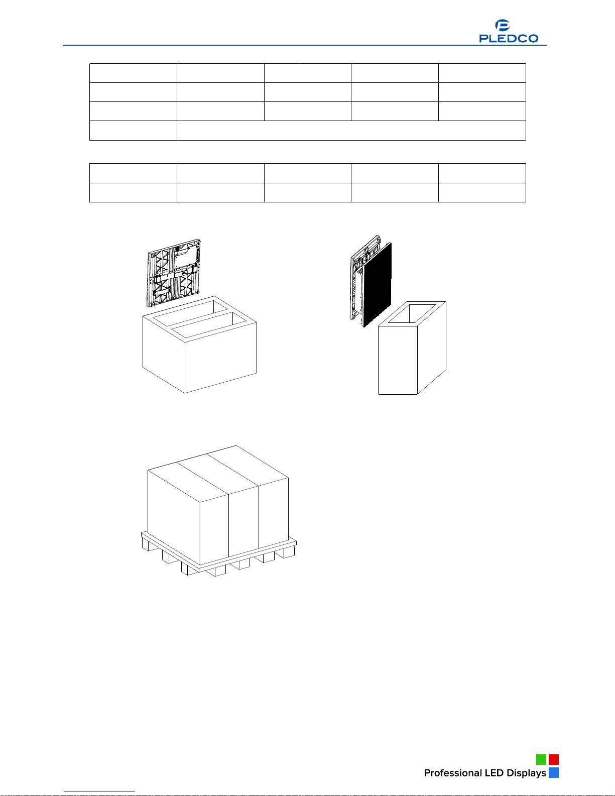
§All partsmustbefullyprotected and packed ingood orderduringtransportation,storage,etc.No
externalpressureshall beapplied on them.
§Nopartof the productcan comeintocontactwithrainbeforeorduringinstallation.Keepthemindry
and cleanplaces.
§All partsmustbeprevented frombeingtrampled,strokeordropped.Followallinstructionswhile
carryingormovingthe parts. Otherwisethe product can besubject toterminaldamage.
Installation
§Beforeinstallation,ensurethatthe supportingstructureorframehassufficientstrengthtoholdthe
displayfirmand safe.
§Forhoistinstallation,the operatormustfollowall instructionsgiven inthisUser sManual,including
wherethe hoistbracketsshouldbelocated,thatthe crane used mustcomewithsufficientcapability
tohoist the product, and thattheoperatingground must havethe strengthtosustainthe crane, etc.
§Mostcomponentsofthe productareheavy.Thereforehighattentionshouldbepaidtopersonnel
safetyduringinstallation.
§All connectionboltsmust befastened firmlyand securely.
Power
§Adisplayistobepowered bya3-phasepowerwith5lines. Thatis,it mustcomewith
an independent neutralline and anindependent ground line.
§Provide the powerand powersupplycircuitsinaccordancewiththe powerconsumption ofthe
display.All circuitsmustcomewithprotection tubesand confirmwiththe localelectricalsafety
standards.
§TheLDU andPSUmustbeinstallednearthedisplay.Cablesfromthe LDU andPSUtothedisplay
Broadcast Indoor
Broadcast Indoor
Broadcast Indoor
www.pledco.com

a
4
cannotbestretchedorimpaired. Powerdistribution fromthe PSUtothedisplaycannotexceed what
isrequired bythisUser sManual.
§The inputvoltageofdisplaycan besetat120VACor220VAC.Butensuretosetit
right beforepowerconnection.
§Donot attempt tofixan impaired cable. Replaceitwithanewone.
§Abigcurrentisproducedthemomentadisplayispowered on.Thereforeanairbreakerthatcan
sustainbigcurrentsshouldbeused asthe masterpowerswitch.
Grounding
§displaysmustbegrounded withan INDEPENDENTground wire.
§Displaystobeinstalled independentlyfromanyarchitecturalstructuremustbeequipped withan
independentgroundwireand,ifnecessary, alightning rod.Thedownleadofthelightningrod should
beinsulated withthe frameof the display.Setthe earthelectrode of the lightningrod andthat of the
ground wireawayfromeachother.
Usage
§LEDson thedisplaycannot bepressured at anytime. Otherwisetheycan bedamaged forgood.
§Followthe stepsmentionedinthisUser sManualwhilecleaningthefrontsideofthedisplay.Only
soft clothingorbrush, neutraldetergent andwateraretobeapplied tothedisplay.
§Powermustbecut offbeforedismantlinganypart formaintenance.
Broadcast Indoor
Broadcast Indoor
www.pledco.com

a Broadcast Indoor
Broadcast Indoor
5
2.Series
Tiles
Thischapterfocusesonthemaincomponent ofdisplay---the Tiles.
Overview
§Tile
§Display
2.1Tile
Tileoverview
Thefront and back viewoftile
The modelsVFI6,VFI8,VFI9.6andVFI12 includedinthe serieshavetilesofthe same
sizebutwithdifferent resolutions. Pleaseseebelow:
Tile VFI6 VFI8 VFI9.6 VFI12
Pixelpitch 6mm 8mm 9.6mm 12mm
Resolution 64X48 48X36 40X30 32X24
Weight 2.8kg
PartNumber
Tile VFI6Tile VFI8Tile VFI9.6Tile VFI12 Tile
Part Number
Theotherseries, the Pseries, usesTilesintegrated withapowersupply.
Thefront and back viewofPTile
Broadcast Indoor
Broadcast Indoor
Broadcast Indoor
Broadcast Indoor
a Broadcast Indoor
Broadcast Indoor
Broadcast Indoor
Broadcast Indoor
a Broadcast Indoor
www.pledco.com

a
6
ParametersofPseriesmodels
Tile VFI6P VFI8P VFI9.6P VFI12P
Pixelpitch 6mm 8mm 9.6mm 12mm
Resolution 64X48 48X36 40X30 32X24
Weight
PartNumber
Tile VFI6PTile VFI8PTile VFI9.6PTile VFI12PTile
Part Number
Packageofthe seriesandthePseriesTiles
2.2display
displayoverview
Adisplayismade ofacertainnumberoftilesand an extrusion frame.Thanks toitssimple
structure, cablingand installationofthe displaycan bedone inabreeze.
Viewofdisplay
Broadcast Indoor
Broadcast Indoor
Broadcast Indoor
Broadcast Indoor
Broadcast Indoor
Broadcast Indoor
Broadcast Indoor
www.pledco.com

7
6
1
53
4
2
PartNumbers
Parts Part Number
1 Tiles
2 Mainextrusion
3 Coverextrusion
4 Columnextrusion Module
5 Nut block
6 Eyebolt set
Given itsmodulesize, thesizeofdisplaychangesbasedon384mminitswidthand on
288mminitsheight.
ViewofPseriesdisplay
aBroadcast Indoor
aBroadcast Indoor
www.pledco.com

Broadcast Outdoor
a
A
Broadcast Indoor
9
3.Installationrequirements
Thischaptercoversrequirementsforinstallation,powersupplyand the controlsystemof
display.
Overview
§Mechanicalrequirements
§Electricalrequirements
§Systemrequirements
3.1Mechanical requirements
displaycomeswithitsownstructuralframewhichmakesinstallation simpleand easy.
Besides,itrequiresastrongand reliablesupportingframeatthe back toholdthe displayfirm.
Whereverthissupportingframeistobeinstalled,onthe ground,ontothe poleoron awall,attention
shouldbepaidtothefollowingfewpoints:
1. Thedisplayshouldbeinstalledinaplacethatallowsaclearandcompleteviewofthe display.
2. Thesupportingframehastobestrongenoughtoprevent the displayfromtumbling.
3. Theinstallationsitemusthavethestrengthtowithstandthetotalweightofthedisplayplusits
structuralframes
4.The displayismeantforindooruseonly.Theambienttemperature,dustand ventilation,
esp. that attheback ofthe displaymust beconsidered when oneischoosingtheinstallationsite.
Atypicalwayofmountingdisplayontoawall:
3.2Electrical requirements
Powerrequirements
§Adisplayworks on AC200-240V,50~60Hz.Eachcolumnofthe displayhasan
independent powersupplycircuit and can thusbepowered byelectricityfromdifferent phases.
§When the max.powerconsumption ofdisplayisless than 3KW,the displaycan
bepowered bysingle-phasepowersupplycircuitswhichinclude alive,neutraland ground wire.
Eachcircuit iscontrolled byanindependent air-breakswitch.
§Butifthe maximumconsumption ofthe displayisover3KW,itshouldbepowered by3-phase
powersupplycircuitsc/walive, neutraland ground wire.The 3-phasepowerdistributespowerto
tilesofeachcolumnon an averagelevel.APSU(powersupplyunit)isused tocontrolthe power.
§Theblock can alsobepowered byAC100-125V, 50~60Hzpowersupplies. But this
needstobespecified inthe production ordersothatit can bepre-set beforegoingout offactory.
Broadcast Indoor
Broadcast Indoor
Broadcast Indoor
Broadcast Indoor
aBroadcast Indoor
www.pledco.com

10
Grounding
The displayshall begrounded attheinstallation site.Ifthe existingpowersupplycircuit
cannotprovide agood ground wireordoesnoteven haveone,itsamusttosetorresetareliable
ground wireforthe display.Good groundingwill enablethe displaytoworkproperlyandcanpreventit
frombeingdisturbed bysurge.
3.3SystemrequirementsfortheControl software
When the WindowsSystemisinquestion:
PCSystemrequirements
§CPUPentiumIVorequivalent, 2.4GHz
§1GBDDR RAM
§Free harddisk space300MB
§Resolution 1280x1024 with32Mvideo memory
§DVI port
§Ethernetconnection
§WindowsXPProfessionalorWindowsVista
Broadcast Indoor
www.pledco.com

Broadcast Outdoor
a
11
4.Componentsofadisplay
Thischaptercontinuestointroduceothercomponentsthat makeupofdisplay.
Overview
§Tile
§MechanicalComponents
§PowerSupplyUnit (PSU)
§LogicDistribution Unit (LDU)
§Video ProcessorUnit (VPU)
§Cables
§Controlsoftware
§Others
4.1Tile
Introductiontothe Tile
The Tileisthe basicdisplayunitofadisplay.The Tileiscomposed ofan
LEDdisplayboard, amask, acontrolboardand somelocks. At theback ofthe Tileisaconnectorthat
integratesthe signalandDC powerinput.
ViewofTile
1
6
5
4
3
2
Partsand PartNumbers
Parts Part Numbers Remark
1 Mask
2 PCB
3 Tilebase
4 ControlBoard
5 Coverplate
6 Lock head
ThePseriesTileincludesanextracovered powerbox.Besides,thePseriesTilehasindependent
signalconnectorsandACinput connectors.
TheviewofPseriesTile
Broadcast Indoor
Broadcast Indoor
Broadcast Indoor
Broadcast Indoor Broadcast Indoor
aBroadcast Indoor
aBroadcast Indoor
www.pledco.com
Broadcast Indoor

12
1
7
6
5
3
2
4
Partsand PartNumbers
Parts Part Numbers Remark
1 Mask
2 PCB
3 Tilebase
4 ControlBoard
5 Coverplate
6 PowerSupply
7 Powercover
4.2Mechanical Components
Besidesthetile, therearesomestructuralcomponentsthat helpmakeupdisplay.
Themainextrusionisthestructuralframeof display,whilethecoverextrusion isused
asadecorativeframetothefrontof thedisplay.Thepolestructureisthesupportingframewheretiles
aretobemounted.It alsocomeswithswitchpowersupplies,powerand signalcircuitsand connectors
tothetiles.
3
4
1
2
aBroadcast Indoor
aBroadcast Indoor
www.pledco.com

13
Eyeboltsareusedforhoist installationofthe display.Theycan beremoved afterinstallation.
Partsand PartNumbers
Parts Part Numbers Remark
1 Coverextrusion
2 Mainextrusion
3 Columnextrusion Module
4 Signalconnector
Similarly,the Pseriesdisplayusesthe mainextrusion and the coverextrusion asitsmain
structuralframe.Butthereisno powersupplyinitspolestructure.Inside itthereareonlyACpower
supplycablesand signalcablesand theirconnectors.
Partsand PartNumbers
Parts Part Numbers Remark
1 Coverextrusion
2 Mainextrusion
3 Columnextrusion Module
4 Columnpole
4.3PowerSupplyUnit(PSU)
ThePSU,shortforPowerSupplyUnit, isthepowercontrolcenterfordisplay.Each
output channelofthe PSUcontrolsone columnoftilesofadisplay. The PSUisalsoinbuiltwithasurge
protectortoprevent the displayfrombeingdisturbed bylighting.
Butifthe powerconsumption ofadisplayisnothigh, an air-breakswitchcan beused inplaceofaPSU.
aBroadcast Indoor
Broadcast Indoor
www.pledco.com

14
Partsand PartNumbers
Parts Part Numbers Remark
1 PSU
2 Airbreaker
4.4LogicDistribution Unit(LDU)
TheLDU isthecentralcontrollerforthedisplay.Itmainlyincludesthecontrolboard
QS5800orQS5003.
Partsand PartNumbers
Parts Part Numbers Remark
1 LDU3000 381-100201
2 Controlboard(QS5800) 380-200202 QS5800
3 Powersupply(5V) 380-200102 5V
4 Fan 380-200302
4.5VideoProcessing Unit(VPU)
The VPUisthe video and DVIsyncprocessorinthe synchronouscontrolsystem.It is
compatiblewithvariousvideo signalinputsaswell asthe DVIsignalinput. Thesesignalsarethen
transmitted tothe LDU viaan opticfiberand shownon thedisplay.
Broadcast Indoor
Broadcast Indoor
www.pledco.com

15
Instrutuion
Parts
1 Powerswitch
2 LCD screen
3 Menu
4 Shortcut keytootherVideo Sources
5 Shortcut keytoDVI Input
4.6Cables
Signalcablebetween LDU and TilesPowercablebetween PSUandTiles
DVI cableNetworkcable
FibercableUSB cable
4.7Control software
www.pledco.com

The series of control software developed by Pledco itself are m
Pledco Tool is the tool software for the LDU to set up, configure, m
PledcoTool
display control of a B roadcast Indoor display.
16
eant for system setting, test and
TIPS: Please refer to the user’s manual of each control software for more information about their
functions and use guidance.
anage and test the display.
Sigma 3000
Sigma 3000 is a powerful control software for an offline system. It can be used to set up, configure the
display as well as control, manage, test and record what is shown offline on the display.
LED Net
www.pledco.com

17
www.pledco.com

a
18
VPU3400 isthe setupand controlsoftwareforthe VPU.Itsused tomanageand controlthe
synchronousdisplayofvariousvideosinputson thedisplayand asalways, systemsetup.
4.8Others
Tocompletethe controlsystem,displaymayalsorequiresomeotheraccessories,say
acomputerinstalled withvariousvideo orpicturetailoringoreditingsoftware, etc.
Ifthe synchronoussystemisinquestion,extravideo deviceslikeaCamera,aRecorddisc,asetof
audioequipmentincludingaprimeamplifier,apoweramplifierand avoicebox,etc.arerequiresas
well.
All the accessoriesmentioned abovearetobeprovided bythe useron theirownbased on actual
applications.
Adisplaywiththe synchronoussystem
Broadcast Indoor
Broadcast Indoor
www.pledco.com

19
5.Installation
Thischapterdescribesthe variousinstallation methodsofdisplay.
Overview
§Preparingthe supportingback structure
§Mountingthe extrusionframe
§Fixingthe Tile
§Othertypesofsupportingstructure
5.1Preparing theback supporting structure
Connectthetopandbottommainextrusion ofdisplaytoitsback supportingstructure
byconnection platesThisisusuallyhowthe displayisinstalled.
Typicalmountingofdisplay:
Theback supportingstructureisusuallybuiltonawall orsitson apoleon the ground.Dependingon
the sizeofthe displayand spaceavailableinstallation site,therecanactuallybemanywaysof
preparingthe supportingstructure.
Belowaresometypicalback supportingstructuresforclients reference:
aBroadcast Indoor
Broadcast Indoor
aBroadcast Indoor
aBroadcast Indoor
www.pledco.com

20
CAUTION:Ifthedisplay istobemountedon awall, onehas toconsiderthewithstandingcapability
ofthewall. Insuchacase,it susuallyadvisedtoinstall thedisplay ontothestructural
columnofthewall.
TIPS Connectionpositionsontheback supporting structuremustmatchthoseonthe
display.Themanufacturercanprovidetheback supportingstructureortheconnection part
fortheclient,butonlyon thecondition thattheclientfullyinformsthemanufacturerof
conditionsintheinstallation site.
5.2Mounting theextrusion frame
Aftermountingthe tiles, installation ofotherstructuralframesaretofollow.
5.2.1 Assembling theextrusion frame
Necessarytools
§8mm open-end wrench
§8mm box-end wrench
§8mm hexagonalkey
§6mm Cross head screwdriver
§Modulartool
Broadcast Indoor
www.pledco.com

21
Connectthe4sidesofthe mainextrusion on aflatground.Insertcornerblocks ontothe connection
positionsofthe mainextrusion. Screwtheminaloosemanner.
Mountthepoleextrusionsinthemiddleofthe frameand mount theirscrews.Withthe aidofaModular
tool,find therightposition forthe screwsand screwthemtight. Thenscrewthe 4cornersof the Main
extrusion tight.
CAUTION:All screwson theframemustbefastenedwheninstallation isfinished.
5.2.2Mounting theframe
Necessarytools
§12mmopen-end wrench
§12mmbox-end wrench
§6mm Cross head screwdriver
§ACrane
Hoist and fixthefinished frameontothe back supportingstructure. Keepaneyeonthehorizontaland
verticalcondition ofthe frameaswell asthe flatsurfaceofthe tiles.Makesureeverythingisingood
www.pledco.com
This manual suits for next models
3
Table of contents