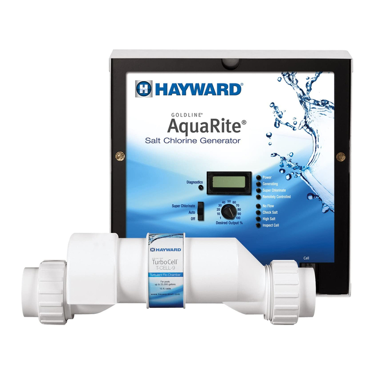
Autopilot ChlorSync User manual

Level Min. Max.
Salt
Ideal3,500ppm(mg/L) 2,700ppm(mg/L) 5,000ppm(mg/L)
WaterFlow 20gpm(4.5m
3
/hr.) 80gpm(18.2m
3
/hr.)
ModelOutput Production/Day
CS30 1.1lbs/0.50kg
CS40 1.4lbs/0.64kg
CS50 1.7lbs/0.77kg
Status Display Indication
Chlorine
Generating
Status
SaltLEDIndicator:
On(solid) Normal SaltLevel=2,700‐5,000ppm(mg/L)‐Recommended ON
Flashing Normal SaltLevel>5,000ppm(mg/L)‐HighSalt ON
On(solid) LoSALt SaltLevel=2,300‐2,700ppm(mg/L)‐LowSalt ON
Flashing AddSALt SaltLevel<2,300ppm(mg/L)‐SaltAdditionRequired OFF
On(solid) Normal NormalOperation ON
Flashing CLnCELLorCLnCELL
SOOn
LowConductivity/HighCurrent(Scaleformation,LowSalt,
Etc.)orOpenCell OFF
On(solid) Normal Normalwaterflowdetected ON
Flashing noFLo LoworNoWaterFlowdetected OFF
‐Cellsize[CS30,CS40,orCS50]
‐WaterTemerature[F.°]
‐SaltConcentration[ppm]
‐CurrentandVoltage
ImmediateSaltCheck(withPoolSync®):
1.OpentheappandselecttheChlorSyncundertheEQUIPMENT options
2.Pressthe3‐dotmenuontheChlorSyncpage
3.SelectSALT,apop‐upwindowwillprompttoREMEASURESALT.
4.SelectOk.
Notes:
֎Thedisplayedsaltlevelisupdatedasfollows
‐Whenthepowerisrestoredorwhenflowisestablished
‐Every12hoursafterpowerisappliedorflowisestablishedifsaltlevelsareabove2,300ppm(mg/L).
‐Every60minutesifsaltlevelis<2,300ppm(mg/L)
INDICATORLIGHTS
Color
Green
Green
Red
Red
RISKOFELECTRICALSHOCK‐Allelectricalconnectionsshouldbemadebyalicensedelectricianorcertifiedelectricalcontractor.
Connecting230Vactoaunitthathasbeenconfiguredto110‐120Vacwillresultinpermanentdamagetotheunit.Damageduetoincorrect
wiringisnotcoveredunderthewarranty.
Warning‐Failuretoheedthefollowingmayresultinpermanentinjuryordeath.
Caution‐Failuretoheedthefollowingmayresultinequipmentdamage.
RISKOFELECTRICALSHOCK‐DisconnectallACpowerwheninstallingorservicingthissystem.Followallstate,local,andNationalElectrical
Code(s)(provincialandCanadianElectricalCode(s)ifapplicable).Usecopperconductorsonly.
RISKOFELECTRICALSHOCK‐Beforepluggingorunpluggingtheunittothepowercenter,firstswitchofftheACpowertothepowercenter.
֎Aerthepurifieroutputlevelissetusingthearrowbuons,theunitwillautomacallymakefineoutputadjustmentsasthewatertemperature
fluctuates.Thispatentedtemperaturecompensationfeaturewilladjustoutputdependingonwatertemperature.
ChlorSync®‐TroubleshootingGuide
Ratedat3,500ppmsalt
֎Whenthewatertemperaturefallsbelow55°F(12.8°C),chlorineproduconisreducedto1%topreventoverchlorinaon.Normalproduconwill
resumewhenthewatertemperaturerisesabovethislevel.
Red
CellLEDIndicator:
Green
Red
FlowLEDIndicator:
Allcellsdraw6.5‐7.5amps
Green
ManualReadings(noPoolSync®):PresstheUpArrow 5times,thenpresstheDownArrow5times.
Thefollowingwillbedisplayed
Forfullmanualuse
QRcode
LTM1034
1of2

Message
‐‐‐‐
Lostcommunicationbetweenthepower
centerandthegeneratorcell Checkthecellcordconnectionatthepowercenterfordamagetothewire.
2.Transformerwiringisincorrect,checkitiswiredproperlyforincoming
voltage.
3.Fuse(10A)mayhavefailed,testandreplaceifnecessary.
4.TransformerorPowerCentercircuitboardhasfailed,replacethePower
Center.(p/n:ECP0312)
AddSalttoachieve3,500ppm(mg/L).LoSALt
1.NopowertothePowerCenter,checkbreaker.Ifunitiswiredtoatime
clock,makesureitisturnedon.
NoDisplayNoDisplay/BlankDisplay
Alternating:
Output/24hr.countdown AlternatingDisplay
Normaloperation,unitisinBOOSTmode.PressandholdboththeUp
ArrowandDownArrowsimutaneouslytoactivate/deactivateBOOST
MODE.
DISPLAYMESSAGES&TROUBLESHOOTING
Problem
OPEnCELLErr Cellbladesarereceivingnocurrent Checkforlooseordamagedwiring,inspectcellfordamage.
NOFLO Insufficientwaterflow
1.Checkpumpforproperoperationandserviceasnecessary.
2.Checkfilter:clean/serviceasnecessary.
3.Checksystemvalvesettingsforproperflowtotheunit.
4.Checkforobstructioninthecell(debrisorscalingaccumulation).
5.Flowsensormayneedtobeservicedorreplaced.ContactalocalService
Centerforassistance.
CLnCELL Cellmaybescaled Highvoltsaregoingtothecell.Checkcellforscale,cleanasnecessaryand
balancewater.
AddSALt
Solution
Saltlevelis2,300‐2,700ppm(mg/L)
Saltlevelisbelow2,300ppm(mg/L) AddSalttoachieve3,500ppm(mg/L).
CLnCELLSOOn Thevoltageatthecellis26to28VDC.Chlorineisstillbeinggenerated.Thecellmaybedirtyorhavecalcium
buildup.Inspectandcleanthecellasneeded.
HIgHCurrErr HighVoltageorOverCurrenthasbeen
detectedandthesystemislocked.
Possibleundissolvedsaltbrushedintothemaindrain.Thesaltwillneedto
dissolveforthisconditiontonormalize.Thesystemwillautomatically
recheckinonehourincrementstoseeifthisconditionpersists.Ifthe
conditionpersists,thesystemwilllockwithahighcurrenterrorfault.A
powerresetwillberequiredtoclearthisfault.
SEnSErr Atemperaturesensorerrorhasbeen
detected.ContactalocalServiceCenterforassistance.
SHrtCELLErr Lowvoltageorashortcircuithasbeen
detected.
Chlorinegenerationishalted.Ifthevoltageremainslow,thesystemwill
automaticallyre‐testfor1hour.Iftheissuepersists,contactalocalService
Centerforassistance.
RS‐485Data(+)‐ TerminalA
RS‐485Data(‐)‐ TerminalB
Black wirefromPoolSync® toGND
YellowwirefromPoolSync®toA
GreenwirefromPoolSync®toB
RedwirefromPoolSync®toVDC
PoolcoverSwitch
(drycontacts)
RS‐485Data(+)‐ TerminalA
RS‐485Data(‐)‐ TerminalB
Connectonlyonered
wireforPoolSync.If
usingPoolSyncon
additionaldevices,
leaveredwireoffon
thoseadditional
devices.
LTM1034
2of2
This manual suits for next models
1
Popular Swimming Pool Filter manuals by other brands
Intex
Intex 128646GS owner's manual
Hayward Pool Products
Hayward Pool Products SP1090WM owner's guide
Hayward
Hayward Star-Clear™ Installation & operation manual
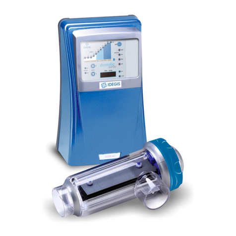
Idegis
Idegis DOMOTIC SERIES Hardware installation and maintenance manual
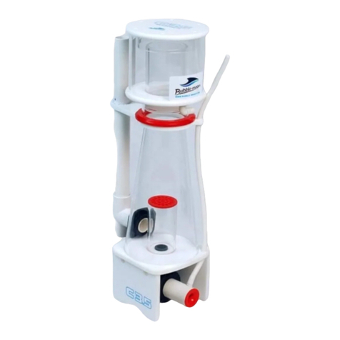
Bubble Magus
Bubble Magus C3.5 user manual
Behncke
Behncke B075 instruction manual

JNS Aquaria
JNS Aquaria ConeS CO Series quick start guide

Pentair Pool Products
Pentair Pool Products D.E. Cartridge Style Filter Quad D.E. Installation and user guide
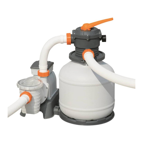
Bestway
Bestway 58499 owner's manual
Pontec
Pontec PondoSkim 12 V operating instructions
BWT
BWT RTM HF S-500 Installation and operating instructions
ProMinent
ProMinent DULCODOS Pool Soft Assembly and operating instructions
