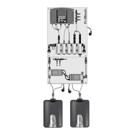
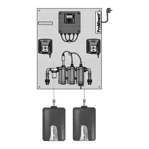
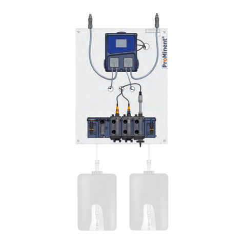
ProMinent DULCODOS Pool Soft User manual

DULCODOS Pool Soft
Assembly and operating instructions
A1746
EN
Original Operating Instructions (2006/42/EC)Part number 984127 Version: BA DD 034 06/15 EN
Please carefully read these operating instructions before use. · Do not discard.
The operator shall be liable for any damage caused by installation or operating errors.
The latest version of the operating instructions are available on our homepage.

In order to make it easier to read, this document uses the male
form in grammatical structures but with an implied neutral sense. It
is aimed equally at both men and women. We kindly ask female
readers for their understanding in this simplification of the text.
Please read the supplementary information in its entirety.
Information
This provides important information relating to the
correct operation of the unit or is intended to make
your work easier.
Safety Information
The safety information includes detailed descriptions of the haz‐
ardous situation, see
Ä Chapter 3.2 ‘Explanation of the safety
information’ on page 10
The following symbols are used to highlight instructions, links, lists,
results and other elements in this document:
Tab. 1: More symbols
Symbol Description
Action, step by step
⇨Outcome of an action
Links to elements or sections of these instructions or other applicable documents
nList without set order
[Button]
Display element (e.g. indicators)
Operating element (e.g. button, switch)
‘Display /GUI’
Screen elements (e.g. buttons, assignment of function keys)
CODE Presentation of software elements and/or texts
General non-discriminatory approach
Supplementary information
Supplemental directives
2

Table of contents
1Identity code.......................................................................... 5
2 About This Product............................................................... 7
2.1 Overview of Equipment................................................. 7
3 Safety and Responsibility...................................................... 9
3.1 Users' qualifications...................................................... 9
3.2 Explanation of the safety information.......................... 10
3.3 General Safety Information......................................... 11
3.4 Intended Use.............................................................. 13
4 Operating Concept.............................................................. 14
4.1 Functions of the keys ................................................. 16
4.2 Changes the set operating language.......................... 17
4.3 Acknowledge fault or warning message .................... 17
4.4 Key Lock .................................................................... 18
5 Storage and transport......................................................... 19
6Assembly............................................................................ 20
6.1 Wall-mounting............................................................. 20
6.2 Fit the antikink device for the bleed line...................... 21
6.3 Hydraulic Installation................................................... 22
6.3.1 Metering system...................................................... 23
6.3.2 Sensors.................................................................... 26
6.4 Electrical Installation................................................... 27
6.4.1 Connect power supply............................................. 27
6.4.2 Install external signal inputs and signal outputs...... 27
6.4.3 Electrical Installation of the Sensors........................ 28
6.4.4 Cable Cross-Sections and Cable End Sleeves....... 28
7 Start Up............................................................................... 29
7.1 Priming and bleeding (with an alpha or Beta pump)... 30
7.2 Adjust the flow sensor switching point........................ 30
7.3 Calibration................................................................... 31
7.3.1 Calibration................................................................ 32
8
[Diagnostics]
....................................................................... 45
8.1 Displaying
[logbooks]
.................................................. 45
8.1.1 Displaying the
[Calibration Log Book]
...................... 45
8.1.2 Reading the
[Error Log Book]
.................................. 46
8.2 Displaying
[simulation]
................................................ 46
8.3 Displaying
[Device Information]
.................................. 47
8.4 Error messages and warning alerts............................ 47
8.5 Help texts.................................................................... 52
9 Maintenance Work.............................................................. 53
9.1 Replacing the chemical storage tanks........................ 54
9.2 Troubleshooting.......................................................... 55
9.3 Disposal of Used Parts............................................... 55
10 Technical Data.................................................................... 56
10.1 Wiring Diagram......................................................... 57
10.2 Drawings, Drilling and External Dimensions of the
DULCODOS®............................................................ 59
11 Spare Parts and Accessories.............................................. 62
Table of contents
3

1 Identity code
DSPa DULCODOS® Pool
Measured variable:
DO2 pH/Timer control H2O2 (DACa)
Auxiliary hardware functions:
0 Screen plotter with measured data backup including SD card
Auxiliary software functions:
1 Screen plotter with measured data backup including SD card
Communication interfaces:
0 none
5 Embedded web server, LAN
Electrical connection:
A 230 V, 50/60 Hz, European standard plug
B 230 V, 50/60 Hz, Swiss plug
Sensor equipment:
0 with sensors
1 Measured variable DO2, without sensors
Design:
0 with logo
1 without logo
Language:
A Swedish O Danish
B Bulgarian P Polish
C Chinese Q Portuguese
D German R Russian
E English S Spanish
F French T Thai
E Czech U Hungarian
H Finish V Slovakian
I Italian W Slovenian
J Japanese X Romanian
K Korean Y Estonian
L Latvian Z Greek
M Lithuanian 1 Turkish
N Dutch
Metering pumps for acid/alkali:
0 without metering pumps
10.8 l/h (DULCO®flex DF2a 0208)
Identity code
5

DSPa DULCODOS® Pool
21.6 l/h (DULCO®flex DF2a 0216)
32.4 l/h (DULCO®flex DF2a 0224)
4 1.8 l/h (alpha ALPc 1002 PVT)
5 3.5 l/h (alpha ALPc 1004 PVT)
61.5 l/h (Beta® BT4b 0401 PVT)
72.8 l/h (Beta® BT4b 0402 PVT)
84.5 l/h (Beta® BT4b 0404 PVT)
Multifunctional valve for acid/alkali pump:
0 none
1with MFV (only for Beta® and alpha)
Metering pumps for disinfection:
0 without metering pumps
10.8 l/h DULCO®flex DF2a 0208, up
to 45/10 m3/h circulation HB/FB*
21.6 l/h DULCO®flex DF2a 0216, up
to 100/20 m3/h circulation HB/FB*
32.4 l/h DULCO®flex DF2a 0224, up
to 140/30 m3/h circulation HB/FB*
4 1.8 l/h alpha 1002, up to 100/20
m3/h circulation HB/FB*
5 3.5 l/h alpha 1004, up to 200/40
m3/h circulation HB/FB*
60.9 l/h Beta® 0401, up to 50/10
m3/h circulation HB/FB*
72.1 l/h Beta® 0402, up to 125/25
m3/h circulation HB/FB*
84.2 l/h Beta® 0404, up to 250/50
m3/h circulation HB/FB*
Multifunctional valve for disinfection
pump
0 none
1with MFV (only for Beta® and
alpha)
Assembly
0 supplied loose without
mounting plate
1 mounted on a base plate
Certification
0 with CE certification
* Calculated for 12% sodium-calcium hypochlorite. HB=indoor pool/ FB=outdoor pool.
Identity code
6

2 About This Product
DULCODOS® Pool metering systems are specifically designed for
the treatment of swimming pool water. Ready mounted and fully-
wired, DULCODOS® Pool metering systems provide pH adjust‐
ment and disinfection using H2O2.
DULCODOS® Pool metering systems are equipped with all the
necessary components mounted on a plate:
nSensors
nController
nMetering pumps
2.1 Overview of Equipment
1
2
3
11a
13a
10a
12a
11b
13b
10b
12b
A1091
4 5 6 7 8
Fig. 1: Overview of equipment for the DULCODOS® Pool Soft (with all options and Beta® metering pumps)
1. pH controller
2. Flow sensor
3. Ball valve, inlet side
4. Dirt filter
5. Flow module with flow sensor
6. pH sensor*
7. Sampling tap
8. Ball valve, outlet side
10a. Injection valve for acid
10b. Injection valve for disinfection
11a. Metering pump for acid
11b. Metering pump for disinfection
12a. Cable, level switch for acid
12b. Cable, level switch for disinfection (only
with Beta® metering pump)
13a. Suction assembly for acid
13b. Suction assembly for disinfection
Not shown Multifunctional valve for acid and disin‐
fection
* To be assembled by the customer.
These components are ready for subse‐
quent installation, but are supplied sepa‐
rately to avoid damage in transit.
Soft components
About This Product
7

2
1
3a
4
3b
A1748
Fig. 2: Control elements for the DULCODOS® Pool Soft (with all
options and Beta® metering pumps)
The following are used as control elements:
1. Controller keys and display
2. Flow meter (by scale)
3a. Stroke adjustment dial on the metering pump (con‐
cealed on the alpha pump)
3b. Stroke adjustment dial on the metering pump (con‐
cealed on the alpha pump)
4. Ball valve, in-line probe housing, outlet side
(not shown
in figure)
Multifunctional valve
Soft control elements
About This Product
8

3 Safety and Responsibility
3.1 Users' qualifications
WARNING!
Danger of injury with inadequately qualified per‐
sonnel!
The operator of the plant / device is responsible for
ensuring that the qualifications are fulfilled.
If inadequately qualified personnel work on the unit
or loiter in the hazard zone of the unit, this could
result in dangers that could cause serious injuries
and material damage.
– All work on the unit should therefore only be
conducted by qualified personnel.
–Unqualified personnel should be kept away
from the hazard zone
Training Definition
Instructed personnel An instructed person is deemed to be a person who has been instructed and,
if required, trained in the tasks assigned to him/her and possible dangers that
could result from improper behaviour, as well as having been instructed in the
required protective equipment and protective measures.
Trained user A trained user is a person who fulfils the requirements made of an instructed
person and who has also received additional training specific to the system
from ProMinent or another authorised distribution partner.
Trained qualified per‐
sonnel
A qualified employee is deemed to be a person who is able to assess the
tasks assigned to him and recognize possible hazards based on his/her
training, knowledge and experience, as well as knowledge of pertinent regula‐
tions. The assessment of a person's technical training can also be based on
several years of work in the relevant field.
Electrician Electricians are deemed to be people, who are able to complete work on elec‐
trical systems and recognize and avoid possible hazards independently based
on his/her technical training and experience, as well as knowledge of pertinent
standards and regulations.
Electricians should be specifically trained for the working environment in
which the are employed and know the relevant standards and regulations.
Electricians must comply with the provisions of the applicable statutory direc‐
tives on accident prevention.
Customer Service depart‐
ment
Customer Service department refers to service technicians, who have
received proven training and have been authorised by ProMinent to work on
the system.
Note for the system operator
The pertinent accident prevention regulations, as
well as all other generally acknowledged safety
regulations, must be adhered to!
Safety and Responsibility
9

3.2 Explanation of the safety information
These operating instructions provide information on the technical
data and functions of the product. These operating instructions pro‐
vide detailed safety information and are provided as clear step-by-
step instructions.
The safety information and notes are categorised according to the
following scheme. A number of different symbols are used to
denote different situations. The symbols shown here serve only as
examples.
DANGER!
Nature and source of the danger
Consequence: Fatal or very serious injuries.
Measure to be taken to avoid this danger
Danger!
–Denotes an immediate threatening danger. If
this is disregarded, it will result in fatal or very
serious injuries.
WARNING!
Nature and source of the danger
Possible consequence: Fatal or very serious inju‐
ries.
Measure to be taken to avoid this danger
Warning!
–Denotes a possibly hazardous situation. If this
is disregarded, it could result in fatal or very
serious injuries.
CAUTION!
Nature and source of the danger
Possible consequence: Slight or minor injuries,
material damage.
Measure to be taken to avoid this danger
Caution!
–Denotes a possibly hazardous situation. If this
is disregarded, it could result in slight or minor
injuries. May also be used as a warning about
material damage.
NOTICE!
Nature and source of the danger
Damage to the product or its surroundings
Measure to be taken to avoid this danger
Note!
–Denotes a possibly damaging situation. If this
is disregarded, the product or an object in its
vicinity could be damaged.
Introduction
Safety and Responsibility
10

Type of information
Hints on use and additional information
Source of the information, additional measures
Information!
–
Denotes hints on use and other useful informa‐
tion. It does not indicate a hazardous or dam‐
aging situation.
3.3 General Safety Information
WARNING!
Danger from hazardous substances!
Possible consequence: Fatal or very serious inju‐
ries.
Please ensure when handling hazardous sub‐
stances that you have read the latest safety data
sheets provided by the manufacture of the haz‐
ardous substance. The actions required are
described in the safety data sheet. Check the
safety data sheet regularly and replace, if neces‐
sary, as the hazard potential of a substance can be
re-evaluated at any time based on new findings.
The system operator is responsible for ensuring
that these safety data sheets are available and that
they are kept up to date, as well as for producing
an associated hazard assessment for the worksta‐
tions affected.
WARNING!
Live parts!
Possible consequence: Fatal or very serious inju‐
ries
– Measure: Disconnect the mains power supply
prior to opening the housing
–De-energise damaged, defective units or units
that have been tampered with by disconnecting
the mains plug
WARNING!
Unauthorised access!
Possible consequence: Fatal or very serious inju‐
ries.
– Measure: Ensure that there can be no unau‐
thorised access to the unit
Safety and Responsibility
11

WARNING!
Operating faults!
Possible consequence: Fatal or very serious inju‐
ries.
– Ensure that the unit is only operated by ade‐
quately qualified and technically expert per‐
sonnel
–Please also observe the operating instructions
for controllers and fittings and any other com‐
ponent groups, such as sensors, sample water
pumps ...
– The operator is responsible for ensuring that
personnel are qualified
CAUTION!
Electronic malfunctions
Possible consequence: Material damage right
through to irreparable damage to the unit
– Do not lay the mains connection cable and
data cable together with cables that are prone
to interference
–Measure: Take appropriate interference sup‐
pression measures
CAUTION!
Warning of feed chemical spraying around
Spraying feed chemical caused by a leak.
Possible consequence: Injuries caused by chemi‐
cals.
– Regularly check the system for leaks.
–Ensure that the system with all components
can be de-energised from outside the danger
zone by appropriate measures (e.g. emer‐
gency stop switch etc.).
NOTICE!
Correct sensor operation / Run-in period
Damage to the product or its surroundings
– Correct measuring and metering is only pos‐
sible if the sensor is working perfectly
–It is imperative that the run-in periods for the
sensors are adhered to
– Allow for run-in periods when planning com‐
missioning
– It may take a whole working day to run in the
sensor
– Please read the operating instructions for the
sensor
Safety and Responsibility
12

NOTICE!
Correct sensor operation
Damage to the product or its surroundings.
– Correct measuring and metering is only pos‐
sible if the sensor is working perfectly
–Check and calibrate the sensor regularly
NOTICE!
Compensation for control deviations
Damage to the product or its surroundings
– This controller cannot be used in control cir‐
cuits which require rapid compensation
(< 30 s)
3.4 Intended Use
Intended Use
The unit is designed to measure and regulate the
pH value and chlorine content in swimming pools.
Usually the integrated metering pumps are
intended for metering the necessary chemicals.
Only connect other feeder assemblies, such as
electrolysis systems or calcium hypochlorite sys‐
tems, if these systems are intended for use in
swimming pools.
Only use the unit in accordance with the technical
details and specifications provided in these oper‐
ating instructions and in the operating instructions
for the individual components (such as sensors, fit‐
tings, calibration instruments, metering pumps
etc.).
All other uses or modifications are prohibited.
Safety and Responsibility
13

4 Operating Concept
A1035
1.
Fig. 3: Operating cross (1) / Active keys are displayed in [black] in the display; inactive keys in [grey].
For example, the following path is presented:
Continuous display ➨ ➨ or
[calibrate]
➨ ➨ or
[slope]
➨ ➨
Continuous display [Calibrate] [Slope]
A1036
Fig. 4: A display change is made within a sequence of actions.
I. Continuous display 1
II. Display 2
III. Display 3
IV. Display 4
The function of the keys is described in table
Ä Chapter 4.1 ‘Func‐
tions of the keys ’ on page 16
.
➨ = describes as a symbol an action by the operator, that leads to
a new possibility for an action.
[Naming in the display]
= square brackets contain the name that
appears with the identical wording in the controller display.
Additional information can be obtained via the key.
Illumination of the display
In the case of an error with the status [ERROR],
the backlight of the display changes from ‘white’ to
‘red’ . This makes it easier for the operator to react
to an error.
Operating Concept
14

Fig. 5: Example of the continuous display when used with a meas‐
uring channel (e.g. pH)
A1177
7.55
7.20
0.50
0.30
25
-15
Fig. 6: Example of the continuous display when used with two
measuring channels (e.g. pH/chlorine)
No time-controlled menu items
The controller does not exit any menu items in a
time-controlled manner, the controller remains in a
menu item until this menu item is exited by the
user.
1. Select the desired parameter in the display using the keys
or .
ðIn front of the selected parameter there is an arrow tip,
which marks the selected parameter.
2. Press
ðYou are now in the setting menu for the desired param‐
eter.
Setting of the various parameters in
the adjustable menus
Operating Concept
15

3. You can adjust the desired value in the setting menu using
the four arrow keys and then save it using the key
ð
Range error
If you enter a value that is outside the
possible setting range, the message
[range error] appears after pressing the
key. By pressing or you return to
the value to be set.
Once the key is pressed, the controller returns to the
menu
Interrupting the setting process
Pressing the key returns to the menu
without saving a value.
4.1 Functions of the keys
Tab. 2: Functions of the keys
Key Function
Confirmation in the setting menu: Confirms and saves the input values.
Confirmation in the continuous display: Displays all information about saved errors and
warnings.
Back to the continuous display or to the start of the respective setting menu, in which you
are currently located.
Enables direct access to all of the controller's setting menus.
Enables direct access to the controller's calibration menu from the continuous display.
Start/Stop of the controller's control and metering function from any display.
To increase a displayed number value and to jump upwards in the operating menu.
Confirmation in the setting menu: Moves the cursor to the right.
Confirmation in the continuous display: Displays further information about the controller
input and output values.
To decrease a displayed number value and to jump down in the operating menu.
Moves the cursor to the left.
Operating Concept
16

4.2 Changes the set operating language
1. Simultaneously press the keys and
ðThe controller changes to the menu for setting the oper‐
ating language.
A1482
Language 2
Language
German
Fig. 7: Menu for setting the operating language
2. Now using keys and you can set the desired operating
language
3. Confirm your selection by pressing the key
ðThe controller changes back to the continuous display
and indicates the selected operating language.
4.3 Acknowledge fault or warning message
If the controller recognises an error
[Error]
, the control is stopped,
the backlight switches to red lighting and the alarm relay is deacti‐
vated. You can access the next value to be set by pressing the
key. In this process, the controller indicates all errors and warn‐
ings. The pending alarm messages can be selected and, if
required, acknowledged/confirmed. If you acknowledge an error,
the alarm relay activates and the backlight switches back to white
light. In the bottom part of the display, the error or warning mes‐
sage that has occurred remains displayed, such as
[Error 01]
, until
the cause has been cleared.
In the event of a warning, e.g. the controller signals that a sensor
has not been calibrated yet, further processing using the controller
is possible with or without acknowledgement of the message.
In the event of an error message
[Error]
,
[e.g.]
the controller signals
that no sensor is connected, then after acknowledgement of the
message, no further processing is possible using the controller.
You must now rectify the error - for this see the chapter on Diag‐
nostics and Troubleshooting.
Operating Concept
17

Fig. 8: Alarm message, controller stops control
4.4 Key Lock
The controller has a key lock. If the key lock is activated, the keys
cannot be pressed. The key lock can be activated or deactivated
by simultaneously pressing and . An activated key lock is indi‐
cated by the symbol.
Operating Concept
18

5 Storage and transport
CAUTION!
– Prior to storage or transport, the
DULCODOS® Pool metering systems must be
free from feed chemicals and water
– Rinse out the media carrying parts, including
the tubes using clean, pure water
– Transport and store the DULCODOS® Pool
metering systems in their original packaging
– Also protect the packaged DULCODOS® Pool
metering systems against damp, exposure to
chemicals and mechanical effects
– Please also observe the operating instructions
for controllers and fittings and other units, such
as sensors, filters, metering pumps ...
Storage temperature: 0 ... 50 °C
Air humidity: < 95% relative air humidity, non-condensing
NOTICE!
If the DULCODOS® Pool metering systems are
stored as an assembly with the sensors, then the
storage and transport conditions must be appro‐
priate for the component with the least resistance
to external influences.
Ambient conditions for storage and
transport without sensors
Storage and transport
19

6 Assembly
6.1 Wall-mounting
Secure the metering system perpendicular and
upright on a wall or a stable mounting system.
The metering system should be freely accessible.
Select the mounting height you require so that:
nAll components are easily accessible
nThe controller's display can be easily read
nThe controller cover can still be parked in the
[Park position]
(150 mm)
nThere is still space for maintenance work beneath the in-line
probe housing (100 mm)
nThere is still room for the chemical storage tank (600 mm)
nThe fluid level of the full chemical storage tanks is below the
metering pumps
nThe maximum priming lift of the metering pumps is not
exceeded.
10 mm
A0924
12
34
Fig. 9: Hanger bolt
1 Rawlplug (design depending on the substrate and in line with
the rawlplug manufacturer's instructions)
2 Hanger bolt
3 U-washer
4 Hexagonal nut
Only assemble the system in a separate, well-ventilated and frost-
proof room. Prevent untrained persons from accessing the room by
structural or organisational means. We recommend that you
comply with the requirements for plant rooms in swimming pools
specified in DIN 19643.
If the system is delivered as a collection of loose parts or without
metering pumps for installation by the customer, assemble all com‐
ponents or the external metering pumps as specified in the over‐
view of equipment in chapter
Ä Chapter 2.1 ‘Overview of Equip‐
ment’ on page 7
.
Assembly
20
This manual suits for next models
1
Table of contents
Other ProMinent Swimming Pool Filter manuals
Popular Swimming Pool Filter manuals by other brands

Bestway
Bestway InflateYourFun 58233 owner's manual

Pool Pro
Pool Pro CPP Series Installation & operating instructions

Hayward
Hayward Pro Series Plus owner's manual

Zodiac
Zodiac eXPERT Instructions for installation and use

Aseko
Aseko ASIN AQUA NET CLF user manual

Pool Pro
Pool Pro CPP Series User manual & operation guide