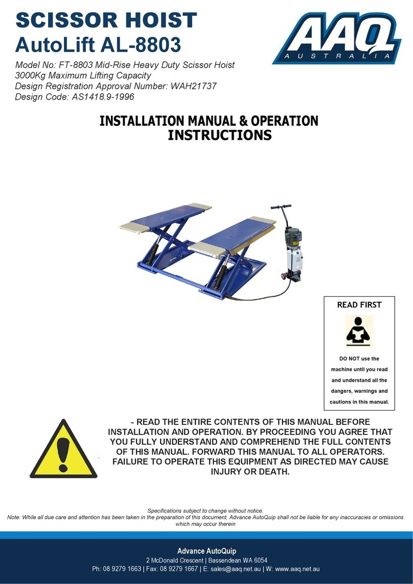
AUTOPSTENHOJ Masterlift 2.30 Manual

Manual no.: 9000114GB
Date: 15.03.2021
ALWAYS KEEP the
operation instructi-
ons ready to hand
on the unit
Read the operation
instructions before
working with the
unit
Masterlift
2.30 / 2.35 / 2.35 Combi
Operation and maintenance
instructions
(TRANSLATED VERSION)

© AUTOPSTENHOJ GmbH
Sandkampstraße 90
D – 48432 Rheine
Tel.: + 49 5971/860202
E-mail: info@autopstenhoj.com
Internet.: www.autopstenhoj.com
Index: s
Before
taking into operation
check system compo-
nents, control, emer-
gency stop and safety
equipment for conditi-
on, damage and
correct function!
2 / 65 9000114GB
Masterlift 2.30 / 2.35 / 2.35 Combi

3 / 65
Masterlift 2.30 / 2.35 / 2.35 Combi
9000114GB
Table of content
1 General......................................................................................................................................5
1.1 Information about the operating manual ....................................................................................5
1.2 Explanation of symbols ..............................................................................................................5
1.3 Warranty and liability..................................................................................................................6
1.4 Spare parts.................................................................................................................................6
1.5 Copyright protection ...................................................................................................................7
1.6 Waste disposal...........................................................................................................................7
2 Safety ........................................................................................................................................8
2.1 General ......................................................................................................................................8
2.2 Customer’s responsibility .........................................................................................................10
2.3 Intended use ............................................................................................................................10
2.4 Work safety .............................................................................................................................. 11
2.5 Personal safety equipment....................................................................................................... 11
2.6 Dangers which may arise from the machine ............................................................................ 11
2.7 Operating personnel.................................................................................................................12
2.8 Behavior in case of danger or accidents..................................................................................12
2.8.1 Preventive measures ...............................................................................................................12
2.8.2 If the worst comes to the worst: Do the right things! ................................................................12
3 Technical data ........................................................................................................................13
3.1 Type designation ......................................................................................................................13
3.1.1 Model ranges with one lifting unit (standard design)................................................................13
3.1.2 Model ranges with two lifting units (Combi design) ..................................................................13
3.2 Name plate...............................................................................................................................14
3.3 Connected loads ......................................................................................................................14
3.3.1 Motor ........................................................................................................................................14
3.3.2 Hydraulic system......................................................................................................................14
3.3.3 Operating values ......................................................................................................................15
3.3.4 Controls....................................................................................................................................15
3.4 Load distribution.......................................................................................................................16
3.5 Weight ......................................................................................................................................18
3.6 Requirements to the place of installation .................................................................................19
4 Structure and function...........................................................................................................20
4.1 General description ..................................................................................................................20
4.1.1 Principle of function..................................................................................................................20
4.1.2 Main components.....................................................................................................................21
4.2 Overview of modules ...............................................................................................................22
4.3 Description of modules.............................................................................................................24
4.3.1 Superstructure..........................................................................................................................24
4.3.1.1 Repair platform Pv or Pv xy .....................................................................................................24
4.3.1.2 Platform Fv Uni ........................................................................................................................24
4.3.1.3 Platform F 420..........................................................................................................................24
4.3.1.4 Platform Fn 420........................................................................................................................24
4.3.1.5 Platform F 440..........................................................................................................................24
4.3.1.6 Platform Fn 440........................................................................................................................24
4.3.1.7 Swivel arm S ............................................................................................................................24
4.3.1.8 Superstructure for Combi lifting platforms................................................................................24
4.3.2 Control box...............................................................................................................................25
4.3.2.1 PLC control unit 'Standard'.......................................................................................................25
4.3.2.2 PLC control unit "Fn" and "Combi"...........................................................................................26
4.3.2.3 Symbols of the short operation instructions ............................................................................27
5 Transport, packing and storage............................................................................................28
5.1 Safety notes .............................................................................................................................28
5.2 Transport inspection.................................................................................................................28
5.3 Packaging ................................................................................................................................28
5.4 Storage.....................................................................................................................................29

4 / 65 9000114GB
Masterlift 2.30 / 2.35 / 2.35 Combi
6 Installation and start-up ........................................................................................................29
6.1 Installation ................................................................................................................................29
6.2 Start-up ....................................................................................................................................29
7 Operation ................................................................................................................................30
7.1 Safety .......................................................................................................................................30
7.2 Operating the lifting platform with repair platform superstructure ............................................31
7.2.1 Rolling the vehicle on ...............................................................................................................31
7.2.2 Lifting the vehicle .....................................................................................................................31
7.2.3 Lowering and rolling o the vehicle..........................................................................................31
7.3 Operating the lifting platform with swivel arm superstructure...................................................32
7.3.1 Rolling the vehicle on ...............................................................................................................32
7.3.2 Lifting the vehicle .....................................................................................................................32
7.3.3 Lowering and rolling o the vehicle..........................................................................................32
7.4 Operating the lifting platform with platform Fv Uni superstructure ...........................................33
7.4.1 Driving the vehicle on the platform...........................................................................................33
7.4.2 Lifting the vehicle .....................................................................................................................33
7.4.3 Lowering and rolling o the vehicle..........................................................................................33
7.5 Operating the lifting platform type F and Fn with platform superstructure ...............................34
7.5.1 Driving the vehicle on the platform...........................................................................................34
7.5.2 Lifting the vehicle .....................................................................................................................34
7.5.3 Lifting the vehicle higher with the wheel free device ...............................................................34
7.5.4 Lowering the vehicle with the wheel free devices ....................................................................34
7.5.5 Lowering and rolling o the vehicle..........................................................................................35
7.6 Operating the Combi lifting platform ........................................................................................36
7.6.1 Driving the vehicle on the platform...........................................................................................36
7.6.2 Lifting the vehicle .....................................................................................................................36
7.6.3 Lowering and rolling o the vehicle..........................................................................................36
7.6.4 Operating the wheel free device on Combi lifting platforms.....................................................36
7.6.4.1 Operating the wheel free device type "Repair platform" ..........................................................36
7.6.4.2 Operating the wheel free device type "Swivel Arm" .................................................................37
8 Maintenance ...........................................................................................................................38
8.1 Safety .......................................................................................................................................38
8.2 Maintenance work ....................................................................................................................39
8.2.1 Maintenance chart....................................................................................................................39
9. Inspections .............................................................................................................................40
9.1 Inspection before commissioning.............................................................................................40
9.2 Annually recurring inspection ...................................................................................................40
9.3 Extraordinary inspection...........................................................................................................40
10. Malfunctions ...........................................................................................................................41
10.1 Action in case of malfunctions..................................................................................................41
10.2 Emergency lowering.................................................................................................................41
10.2.1 Emergency lowering of lifting platforms with PLC control unit ................................................42
10.2.1.1 Pneumatic connection..............................................................................................................42
10.2.1.2 Lowering the lifting platform .....................................................................................................42
10.2.1.3 Lowering the wheel free device in the superstructure "Repair platform"..................................42
10.3 Fault display PLC control unit ..................................................................................................43
11 Appendix: Wiring diagrams ..................................................................................................45
12 Appendix: Hydraulic circuit diagrams .................................................................................55
13 Appendix: Other circuit diagrams ........................................................................................60

5 / 65
Masterlift 2.30 / 2.35 / 2.35 Combi
9000114GB
1 General
1.1 Information about the operating manual
This operating manual describes the installation, operation and maintenance of the machine.
Strict compliance with all the specied notes on safety and instructions is essential for safe working and proper
handling of the equipment.
Apart from that, all accident prevention instructions valid at the place of use and the general safety regulations
must also be adhered to.
This operating manual is part of the product and should always be kept in the immediate vicinity of the ma-
chine, accessible for the personnel entrusted with installation, operation, maintenance and cleaning.
For better representation of the explanations, the graphical artwork in this manual is not strictly according to
scale, but may slightly vary from the actual design of the machine.
The operating manuals of the supporting components apply alongside this operating manual.
Please observe the notes contained therein - especially the safety notes.
1.2 Explanation of symbols
Important safety and machine-technical notes in this operating manual are marked with symbols. The notes
must be adhered to in order to avoid accidents, personal injuries and damage to property.
WARNING!
This symbolizes dangers that can lead to adverse eects on health, injuries, permanent physical dam-
age or to death.
Adhere at all costs to the notes specied regarding work safety, and be particularly careful in these
cases.
WARNING! Danger of electric current!
This symbol draws attention to dangerous situations involving electrical currents. There is a danger of
serious injury or death if the safety notes are not complied with. The work may only be carried out by
qualied electricians.
ATTENTION!
This symbolizes notes, which if not complied with, can lead to damages, malfunctions and/or break-
down of the machine.
NOTE!
This symbol highlights tips and information that are to be observed for ecient and disruption-free operation of
the machine.

6 / 65 9000114GB
Masterlift 2.30 / 2.35 / 2.35 Combi
1.3 Warranty and liability
All information and notes in this operation manual are provided under due consideration of valid regulations, the
latest technical status of development as well as our years of expertise and experience.
The translation of this operation manual has also been made to the best of our knowledge.
We do not accept any liability for errors in translation. The version of the operation manual marked with “Origi-
nal version” on the front page of the operation manual supplied with the lift shall be binding.
For optional design versions, the use of additional ordering options or the implementation of the latest technical
modications the actual scope of delivery may dier from the descriptions and illustrations in this manual. If you
have any questions please contact the manufacturer.
NOTE !
This operation manual must be thoroughly read before starting any work with the equipment, especially before
commissioning ! The manufacturer assumes no liability for damages or disruptions that occur as a result of
non-compliance with the operation manual.
This operation manual must be kept at the lift and accessible for all persons working on or with the lift. Handing
over the manual to third party is not permitted and is subject for compensation. Further rights remain reserved.
We reserve the right to technical changes to the product within the framework of improving the usability and
further development.
This lift is guaranteed, covering faults due to manufacturing or material defects, provided that the installation,
operation and maintenance instructions are observed. The warranty implies that during the warranty period the
manufacturer is committed either to repair or to replace – after own decision - defective spare parts tted in the
lift. No other warranty claim can be put in under warranty.
1.4 Spare parts
IMPORTANT:Spare parts used in the lifts are quality tested and comply with the criteria laid down in DS/EN
1493:2010. Please note that the use of safety spare parts or other essential components which do not fulll
these criteria may result in the type approval becoming void and the lift will thereby no longer keep the safety
regulations dened by the manufacturer together with the relevant authorities.
The manufacturer’s product/deciency liability and warranty cannot be claimed if concrete damages or failures
are a result of the use of spare parts not originating from the factory.

7 / 65
Masterlift 2.30 / 2.35 / 2.35 Combi
9000114GB
1.5 Copyright protection
This operating manual is to be treated as condential. It is solely intended for persons having to work on or with
the equipment. Passing this operating manual on to third parties without a written conrmation is not permitted.
If this should be required, please contact the manufacturer.
NOTE!
Contents, texts, drawings, pictures and other representations are protected by copyright law and are subject to
further commercial protection rights. Any misuse is punishable.
Reproduction of any kind - even in form of excerpts - as well as the utilization and/or disclosure of its content
without the written consent of the manufacturer is not permitted.
Violations oblige to compensation. Further rights remain reserved.
1.6 Waste disposal
If no agreement concerning take-back or waste disposal has been made, disassembled components must be
passed on for recycling after correct dismantling:
Metal material residues must be scrapped
Plastic elements must be forwarded for recycling of plastics
Other components must be sorted by material properties
ATTENTION!
Electric scrap, electronic components, lubricants and other auxiliary materials must be treated as haz-
ardous waste and must only be disposed of by specially approved waste disposal companies!
Consumables like greases, oils, conserving and cleansing agents must be removed from the device in a type
specic and environmental manner. Use suitable and approved storage containers for the repective consum-
ables. Mark these containers according to their content, lling level and data and store them until nal waste
disposal in such a way, that any accidental use is ruled out.

8 / 65 9000114GB
Masterlift 2.30 / 2.35 / 2.35 Combi
2 Safety
This section oers an overview of all important safety aspects for an optimal protection of personnel against
danger and ensures safe and disruption-free operation of the machine.
In addition to this, concrete notes on safety to avert danger are provided and marked with symbols in the indi-
vidual chapters. Furthermore, any pictograms, signs and labels on the machine are to be observed and kept
legible at all times.
2.1 General
At the time of development and manufacture the equipment complies with the valid and established technical
rules and regulations and is safe to operate. However, danger may arise from this machine if it is used unpro-
fessionally by untrained personnel, or if it is used improperly or not for the purpose it is intended for. Each per-
son entrusted with work on or with the machine must have read and understood the operating manual before
starting work.
The customer is advised to demand a written conrmation that all relevant persons have read the operating
manual.
Changes of any kind as well as attachments or conversions to the machine are prohibited.
Safety, warning and operation related decals on the machine must always be kept in legible condition. Dama-
ged decals or stickers must be immediately replaced.
Specied settings and adjustment ranges must be strictly complied with.
On the following page you can nd an example of the EC Certicate of Conformity.
The original certicate is part of the technical documentation supplied with the lift.

9 / 65
Masterlift 2.30 / 2.35 / 2.35 Combi
9000114GB
Example of an EC Statement of Conformity
COPY

10 / 65 9000114GB
Masterlift 2.30 / 2.35 / 2.35 Combi
2.2 Customer’s responsibility
•This operating manual should always be kept in the immediate vicinity of the machine, accessible for the
personnel entrusted with installation, operation, maintenance and cleaning.
•The machine must only be operated in technically perfect and safe condition.
•Always ensure free access to all safety features and check these at regular intervals.
Details concerning industrial safety refer to directives of the European Union valid at the time the machine was
manufactured. The customer is obliged to determine compliance of work safety measures specied with the
current status of legal statutes and to observe any new regulations over the entire period in which the machine
is used. Outside of the European Union, the laws on industrial safety and regional directives and regulations
valid at the place of use of the machine are to be complied with.
The generally valid notes on industrial safety and accident prevention instructions as well as the valid environ-
mental protection regulations applicable at the place of use are to be observed and adhered to alongside the
notes on industrial safety in this operating manual.
The customer and personnel authorized by him/her are responsible for the disruption-free operation of the ma-
chine as well as for unambiguous determination of responsibilities during installation, operation, maintenance
and cleaning of the machine.
Details of the operating manual are complete and must be adhered to without limitation!
Furthermore, the customer must also ensure that:
•Other dangers that result from special working conditions at the place of use are determined in a risk as-
sessment.
•All other instructions and notes on safety that result from the risk assessment of workplaces on the ma-
chine are summarized in operating instructions.
2.3 Intended use
Operational safety is only guaranteed when adhering to the intended use of the device.
The lifting platform solely serves the purpose of lifting and lowering vehicles with the total weight stated on the
name plate. .
The lifting platform has been designed and built for the use inside workshops.
Riding, climbing and/or standing on the lifting platform as well as using it for lifting or lowering loads other than
the ones specied above or installing and operating it outside in an unprotected environment is prohibited.
ATTENTION !
Any other use of the device that diers from this or exceeds this is prohibited and is not considered
unintended use!
Claims of any kind against the manufacturer and/or his authorized representatives resulting from damage
caused by unintended use of the device are excluded. The customer is solely liable for any damage occurring
during unintended use.
Intended use also includes correct adherence to assembly, operating, maintenance and cleaning instructions.

11 / 65
Masterlift 2.30 / 2.35 / 2.35 Combi
9000114GB
2.4 Work safety
Compliance with the notes on safety can help to avoid personal injury and material damage when working on
the machine. Failure to comply with these notes will cause a considerably risk of injury for persons and danger
of damage or destruction of the machine.
Non-compliance with the safety regulations causes the exclusion of any liability or compensation claims against
the manufacturer or his representative.
2.5 Personal safety equipment
In principle, the following is to be worn when working on or with the machine:
Protective working clothes
Tight tting work clothing (minimal tear strength, no wide sleeves, no rings or
other jewelers etc.)
Safety gloves
Safety boots
for protection against heavy falling down objects and slipping on
non-skid proof ground
2.6 Dangers which may arise from the machine
The machine was subjected to a risk analysis. The resultant construction and design of the machine corre-
sponds to the current status of technology.
However, certain remaining risks cannot be avoided!
This device works with electrical voltage.
WARNING! Danger of electric current!
Electrical power can cause severe injuries. There is a danger to life caused by electric current if the
insulation or individual components are damaged.
Switch o the main switch and secure against switching on again before maintenance, cleaning or repair work.
Switch o the power supply before starting work in the electrical system and make sure that the system is dead.
Do not remove any safety features or do not modify such installations in a way that would adversely aect their
function.
The equipment is supported by hydraulic components.
WARNING! Danger of injury!
Hydraulic power can cause severe injuries. In case of damage to individual components uid may es-
cape under high pressure and cause injury and material damage!
Always relieve all pressures before starting work in the hydraulic system.
Do not remove any safety features or make them inoperative as a result of modications.
Do not change any pressure settings beyond the values specied in this operating manual.

12 / 65 9000114GB
Masterlift 2.30 / 2.35 / 2.35 Combi
2.7 Operating personnel
The device must only be operated and serviced by authorized, trained and instructed expert persons who:
•are at least 18 years of age and
•have been thoroughly instructed in operation and
•can provide evidence of their suitability to operate lifting platforms and
•have been entrusted in writing by the operating company to operate the lifting platform
An instructed person is someone who has been trained and, if necessary, instructed practically in the tasks en-
trusted to him/her and the possible dangers resulting from improper actions; and who has been instructed both
about the necessary protective features and about protective measures.
Qualied personnel include those who can assess the work entrusted to them and recognize potential dangers
based on their specialist training, knowledge and experience as well as their knowledge of appropriate conditi-
ons.
If personnel do not have the necessary knowledge, then they are to be trained accordingly.
The equipment must only be operated and serviced by persons who are able to perform their work in a reliable
manner. For this purpose, any mode of operation that adversely aects the safety of persons, the environment
or the machine is to be avoided. Persons who are under the inuence of drugs, alcohol or medication that ae-
cts their responsiveness may under no circumstances carry out work on or with the machine.
The employment of personnel must be based on the applicable regulations concerning age and qualication.
The responsibilities concerning operation and maintenance must be clearly specied in order to avoid uncer-
tainties in competence.
The operator must ensure that unauthorized persons keep a sucient clearance to the equipment.
The operator is obliged to report immediately any changes to the equipment which adversely aect the safety
to the operator.
2.8 Behavior in case of danger or accidents
2.8.1 Preventive measures
•Always be prepared for accidents or re !
•Keep rst aid equipment (rst aid kit, blankets, etc.) and reghting equipment close to hand.
•Make personnel familiar with the location and use of safety, accident reporting, rst aid and rescue equip-
ment and have this training conrmed.
•Clear access routes for rescue vehicles.
2.8.2 If the worst comes to the worst: Do the right things!
•Operate the EMERGENCY STOP to shut down the machine.
•Inform the responsible person at the place of use.
•Alarm a physician and the re brigade.
•Rescue persons from the danger zone, start rst aid measures.
•Keep access routes for rescue vehicles clear.

13 / 65
Masterlift 2.30 / 2.35 / 2.35 Combi
9000114GB
3 Technical data
3.1 Type designation
3.1.1 Model ranges with one lifting unit (standard design)
Example: ML 2.35 S aav 135
Design key *)
Identication of superstructure:
a = telescopic
aa = double telescopic
v = slidable
n = with wheel free device
Superstructure:
S = Swivel arms
P = Repair platforms
F = Platforms
Load bearing capacity:
30 = 3000 kg
35 = 3500 kg
Number of rams of the lifting unit
Series designation "Masterlift"
*) Design key:
for swivel arm superstructure: Piston distance: 135 = 1335 mm
230 = 2285 mm
260 = 2600 mm
for platform superstructure: Length of platforms: 420 = 4200 mm
440 = 4400 mm
for platform/wheel support (Fv) Uni = equipment with universally plugable leaf
superstructure: prings for exible adaptation of the platform to
dierent wheel bases
for repair platform superstructure: Adjustment range 120-180 = 1200 - 1800 mm
of the repair platforms: 140-200 = 1400 - 2000 mm
160-220 = 1600 - 2200 mm
170-240 = 1700 - 2400 mm
3.1.2 Model ranges with two lifting units (Combi design)
Identication for combined lifting unit
|
Example: ML 2.35 Combi Pv140-200
│ │ │ │
│ │ │ │
Identication as above

14 / 65 9000114GB
Masterlift 2.30 / 2.35 / 2.35 Combi
3.2 Name plate
The name plate is located on the control and contains the following information:
Manufacturer
Type designation
Machine serial-no.
Year of manufacture
Load bearing capacity
Design key
Operating pressure
Power input
Supply voltage
3.3 Connected loads
3.3.1 Motor
Voltage: 230 / 400 V (Δ/Y)
Phases / frequency: 3p+PE / 50 Hz
Current consumption: 16 A
Power input: 3.0 kW
Rated speed: 2770 rpm
3.3.2 Hydraulic system
Max. pressure of hydraulic pump: 250 bar
Hydraulic pump ow volume: 10.6 l/min
Max. ow volume of ow control valve: 8,6 ± 0.8 l/min
without wheel free device with wheel free device Combi
Capacity (kg) 3000 3500 3500 3500
Operating pressure
(bar)
150 175 200 215
Setting of pressure
relief valve (bar)
160 185 210 225
Total oil volume in
circuit
approx. 10 l approx. 10 l approx. 14 l
Tank withdrawel volume approx. 6.0 l approx. 6.5 l approx. 6.5 l approx. 6.0 l

15 / 65
Masterlift 2.30 / 2.35 / 2.35 Combi
9000114GB
3.3.3 Operating values
Lifting/lowering speed approx. 6 cm/s
Permanent sound level ≤ 70 dB(A)
Operating temperature range -10... +60 °C
Operating pressure for emergency lowering (at port A): min. 6 bar
3.3.4 Controls
DT-PLC Control
(programmable push button control)
Supply line via main switch 400V / 3p+N+PE / 50Hz
Voltage transformer primary/secondary 230V AC / 24V DC
Control voltage 24V DC
Sensor voltage 24V DC
Voltage of magnetic coil 24V DC

16 / 65 9000114GB
Masterlift 2.30 / 2.35 / 2.35 Combi
3.4 Load distribution
Repair platform type superstructure
Front load ratio (Fv) : rear load ratio (Fh)
Fv : Fh = 3 : 2 and 2 : 3
This assumption is based on a load bearing rectangle
with a width (track width) x length (wheel base) of
1.00 m x 1.40 m respectively 1.70 m x 1.40 m.
= Roll-on direction
Swivel arm type superstructure
Front load ratio (Fv) : rear load ratio (Fh)
Fv : Fh = 3 : 2 and 2 : 3
This assumption is based on a load bearing vehicle
frame with a width of 1.00m.
= Roll-on direction
Platform type superstructure
Front load ratio (Fv) : rear load ratio (Fh)
Fv : Fn = 3 : 2 and 2 : 3
This assumption is based on a platform projection at
front (v) and rear (h) of 300 mm each from the middle
of the wheel to the end of the platform.
= Roll-on direction

17 / 65
Masterlift 2.30 / 2.35 / 2.35 Combi
9000114GB
Platform Fv Uni superstructure
Front load ratio (Fv) : rear (Fh)
Fv: Fn= 3 : 2 and 2 : 3
This assumption is based on a pavement
projection at front (v) and rear (h) of 300
mm each from the middle of the wheel to
the end of the pavement.
= Roll-on direction

18 / 65 9000114GB
Masterlift 2.30 / 2.35 / 2.35 Combi
3.5 Weight
Superstructure: All components fastened on the hydraulic cylinders
Cassette: Steel cassette concreted in the foundation to take up the lifting unit
Lifting unit: Hydraulic cylinders with guides/stung boxes, synchronization bar, hydraulic unit incl. hydraulic oil,
control and sensor ladder rack for the signal tone. The lifting unit is built into the cassette, except the control.
Assembly Lifting platform (types) Weight (kg) approx.
Superstructure
Pv 120-180, Pvv 120-180 175
Pv 140-200, Pvv 140-200 200
Pv 160-220, Pvv 160-220 225
Pv 170-240 250
Sa 230 Sport 200
Saa 135 400
Saa 230 250
Saa 260 235
Saav 135 430
Sav 230 300
F420 930
Fn420 990
F440 700
Fn440 1180
Fv Uni 700
Combi Pv 140-220 500 / 200
Combi Pv 160-220 500 / 225
Combi Saa 500 / 400
Combi Saav 500 / 430
Cassette
Cassette 1335 300
Cassette 2285 520
Lifting unit
3.5 t / 1335 520
3.5 t / 2285 540
3.0 t / 2285 540
3.5 t / Fn 520

19 / 65
Masterlift 2.30 / 2.35 / 2.35 Combi
9000114GB
3.6 Requirements to the place of installation
The lifting platforms consist of an above oor and a under oor component. They can be installed as standard,
basement or ceiling installation version.
Hydraulic cylinders, hydraulic pump, motor, valves and parts of the controls are tted in-ground in a covered
foundation frame or in a cassette. The foundation depth thereby depends on the design of the lifting platform
(see “Technical Data”).
The superstructure, possibly with integrated wheel free device, and the control panel represent the above oor
tted modules.
The lifting platform must only be installed in dry indoor workshops or in outdoor areas protected against the
inuences of weather (wind-load, humidity etc.). The installation requires a level oor. The installation location
must be free of high dust and/or dirt loads. It must be assured that the foundation will remain dry and clean
during the entire utilization time of the lifting platform.
When working on the oor edge (e.g. tiling of the oor) the shell tubes of the hydraulic cylinder and the sealing
band must be appropriately protected against dust, sand, mortar, cleansing agents and other foreign matter.
The manufacturer or his representative will not accept any liability, compensation and/or warranty claims for
damage caused by the entry or introduction of foreign materials into the working range of the lifting platform.
NOTE!
Before starting work inform the person responsible for building work about the necessary precautions in the
vicinity of the lifting platform!
Use of the lifting platform in wet rooms, such as a car wash, is only permitted in combination with special
optional equipment, which is available from the manufacturer on request. In this case the controls must be
installed well protected against moisture at a place with unobstructed view to the danger zone.

20 / 65 9000114GB
Masterlift 2.30 / 2.35 / 2.35 Combi
4 Structure and function
4.1 General description
4.1.1 Principle of function
The lifting columns under the left and right hand side of the vehicle have the function of lifting and lowering the
vehicle. The following superstructures for vehicles are available for selection:
Superstructure "Repair platform"
The superstructure is designed as longitudinal girder and must be attached to the specied locations on the ve-
hicle chassis. During the lifting process the vehicle is lifted up by the chassis, wheels and underside of vehicle
remain accessible, except the sills.
Superstructure "Swivel Arm"
Single or double telescopic, partly slidable. The superstructure must be attached to the specied locations on
the vehicle chassis. During the lifting process the vehicle is lifted up by the chassis, wheels and underside of
vehicle remain accessible.
The swivel arms are of telescopic design and can therefore be exactly positioned to match smaller as well as
larger vehicles.
Superstructure "Platform", type Fv-Uni
This superstructure picks up the vehicle with wheel supports under the wheels. During the lifting process the
vehicle remains with its wheels on the wheel supports, most of the underside of the vehicle is freely accessible.
The wheel supports can be laterally plugged into the longitudinal girder at dierent positions. This enables the
lift to lift vehicles with dierent wheel bases.
Superstructure "Platform"
This superstructure picks up the vehicle by the wheels. During the lifting process the vehicle remains on its
wheels, the underside of the vehicle is freely accessible.
Lifting platforms of types Fn are additionally equipped with scissor wheel free device, which are integrated in
the platforms. These scissor wheel free devices enable further lifting of the vehicle by the chassis, after it has
been lifted to highest position with the superstructure "Platform". With this device the wheels can additionally be
cleared.
Combi-type lifting platforms are equipped with the superstructure "Platform" on the outer lifting unit and a
second, integrated superstructure ("Repair platform" or "Swivel Arm") on the inner lifting unit.
The vehicle can be lifted either with the outer lifting unit ("Platform"), or with the inner lifting unit ("Repair plat-
form" or "Swivel Arm"). The max. lifting height with both lifting units fully extended is max. 1905 mm.
For the lifting process the vehicle must be positioned in roll-on direction centrally in the area of the lifting plat-
form, so that the superstructures are evenly arranged under the left and right hand sides of the vehicle, accor-
ding to the specied load distribution.
Movement of the lifting platform is triggered by actuating the buttons on the control box. The hydraulic cylinders
move in or out in compliance with the chosen direction of movement. The superstructure with the vehicle is
thereby lifted or lowered.
Other manuals for Masterlift 2.30
1
This manual suits for next models
2
Table of contents
Other AUTOPSTENHOJ Lifting System manuals


