AutoTwirler Pro Rotisserie User manual

FRONT
REAR
STRAP STRAP
DO NOT STRAP
THIS WAY!
DO NOT STRAP
THIS WAY!
STRAP STRAP
STRAP
TRAILER TIEDOWN INSTRUCTIONS
1. POSITION THE ROTISSERIE CENTERED ON THE TRAILER AND SET THE CASTER WHEEL LOCKS.
2. ATTACH TIE DOWN STRAP TO THE BASE OF THE ROTISSERIE UPRIGHT THAT IS ON THE REAR END OF THE TRAILER.
CONNECT THE OPPOSITE END OF THE STRAP TO THE FRONT OF THE TRAILER.
3. ATTACH TIE DOWN STRAP TO THE BASE OF THE ROTISSERIE UPRIGHT THAT IS ON THE FRONT END OF THE TRAILER.
CONNECT THE OPPOSITE END OF THE STRAP TO THE REAR OF THE TRAILER.
4. WITH BOTH STRAPS ATTACHED AND PULLING THE ROTISSERIE INTO ITSELF, TIGHTEN THE STRAPS AND
MAKE SURE THE STRAPS ARE SUCURE FOR SAFE TRANSPORTATION OF THE ROTISSERIE.
5. AFTER SECURING THE ROTISSERIE BY THE FRONT AND REAR, STRAP BASE OF ROTISSERIE FROM SIDE TO SIDE ON
TRAILER SO THE ROTISSERIE CAN NOT MOVE IN ANY DIRECTION.
675 N 600 W STE 2 LOGAN UT. 84321
email: [email protected] website: www.autotwirler.com
phone #: 1 (435) 752-3921
ATTENTION WITH WHEEL
KIT INSTALLED WEIGHT
LIMIT IS 1650LB
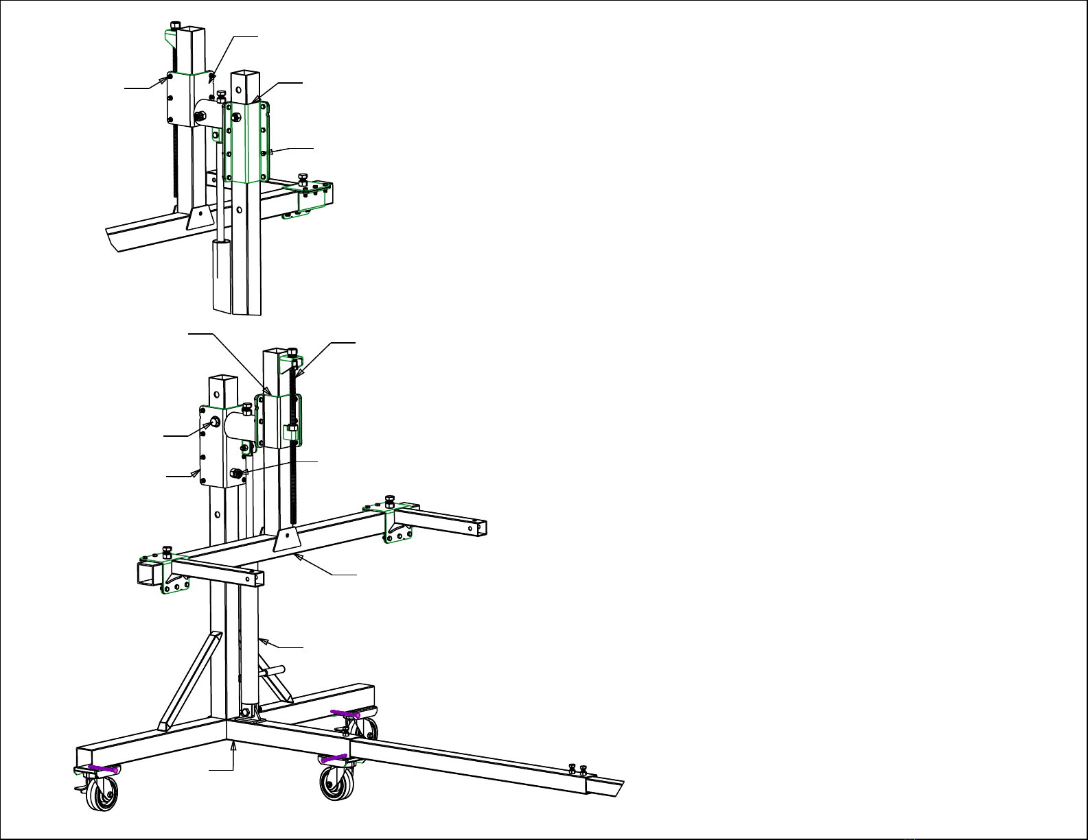
SEE DETAIL A
SEE DETAIL B
STAND
T-ARM
STAND HYDRAULIC JACK
T-ARM BALANCER
"W" BRACKET
STAND HEIGHT TRAVEL BEARING
3/4" X 4 1/2" BOLT
ACME THREADED ROD JACK
STAND OUTER PIVOT
L-BRACKET
STAND OUTER PIVOT
"W" BRACKET
3/8" X 1" BOLT
3/8" x 1" BOLT
T-ARM BALANCER
L-BRACKET Auto Twirler Jack Instructions
Adjusting the Stand Hydraulic Jack
1. Before you raise or lower the Auto Twirler Pro or
Elite you need to remove the 3/4” x 4 1/2” bolt with
accompanying nut and washer.
2. Loosen all eight 3/8” x 1” bolt and nuts located on the
L & W bracket clamp. Loosen them just enough to
allow the jack to be able to raise or lower.
3. Adjust the rotisserie to the height desired. Reinsert the
3/4” x 4 1/2” bolt with accompanying nut and washer,
make sure it is securely tightened.
4. Re-tighten all eight of the 3/8” x 1” bolts and nuts to
cause the L & W bracket to clamp down securely to the
Stand.
5. Readjust the Height Travel Bearing by snugging it up
and then backing it off ¼ turn and locking the bolt
down with the lock nut.
Adjusting the T-Arm Jack
1. Loosen all six 3/8” x 1” bolt and nuts located on the L & W
bracket clamp. Loosen them just enough to allow the jack to be
able to raise or lower.
2. To move the jack turn the Acme nut that is welded to the top of
the Acme threaded rod jack. Adjust the T-Arm to the desired
height.
3. Re-tighten all six of the 3/8” x 1” bolts and nuts to cause the
L & W bracket to clamp down securely to the T-Arm.

Reassemble of a pivot on a Pro Rotisserie
1. If the T arm is attached to the inner pivot it will need to be removed.
2. Make sure the O ring is seated in the Groove closets to the bracket on the Inner Pivot Piece.
3. Using a very stiff grease place 24 of the 3/8” bearings in the groove next to the O-ring and 24 of the 3/8”
bearings in the groove farthest from the Bracket.
4. Gently slide the inner pivot, with the 3/8” bearings into the outer pivot.
5. Line up the empty groove on the inner pivot with the hole on the side of the outer pivot part.
6. Drop in a 5/8” bearing.
7. Tighten down the set screw until it is snug up against the 5/8” bearing.
8. Back the set screw off about ¼ turn.
9. Tighten the Set/Lock nut down on the Set screw. This will hold the 5/8” Bearing in the groove. Which
will keep the pivot intact.
10. Remount the T arm to the Inner pivot.
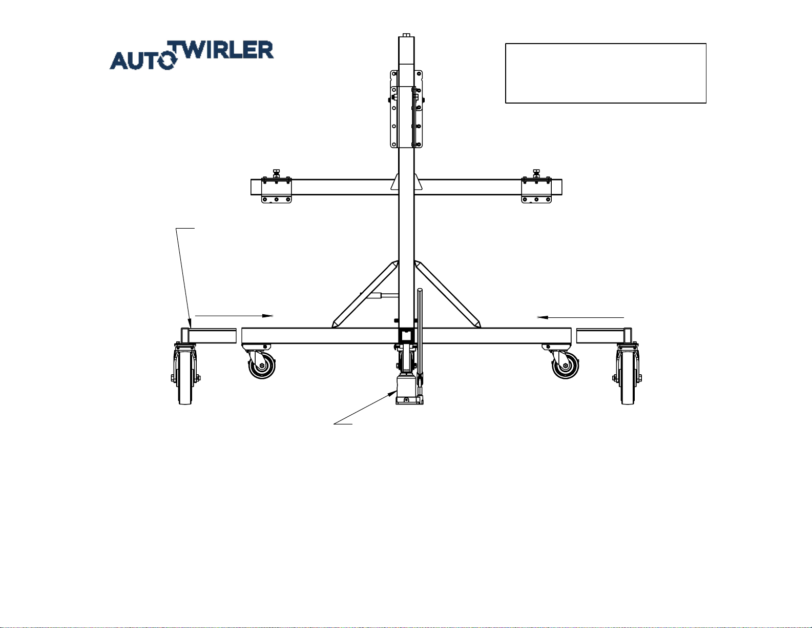
PLACE JACK BENEATH ROTISSERIE AS SHOWN
DIRECTLY BELOW THE UPRIGHT.
INSERT OFF ROAD WHEEL KIT
COMPLETLY INTO THE ENDS
OF THE ROTISSERIE.
INSERT INSERT
OFF ROAD WHEEL KIT INSTRUCTIONS
Chock wheels on the opposite end of the rotisserie that you are jacking up.
1.
Place jack directly under rotissierie stand. (See picture)
2.
Raise jack high enough to easily insert the Off Road Wheel Kit.
3.
Position wheels to extend inside of the rotisserie so they don't extend the length of the rotisserie.
4.
Insert Wheel Kit wheels all the way in until it stops. (See picture)
5.
Lower the Jack and repeat all of the steps for the opposite end.
6.
2/14/2017
675 N 600 W STE 2 LOGAN UT. 84321
email: [email protected] website: www.autotwirler.com
phone #: 1 (435) 752-3921
ATTENTION WITH WHEEL
KIT INSTALLED WEIGHT
LIMIT IS 1650LB
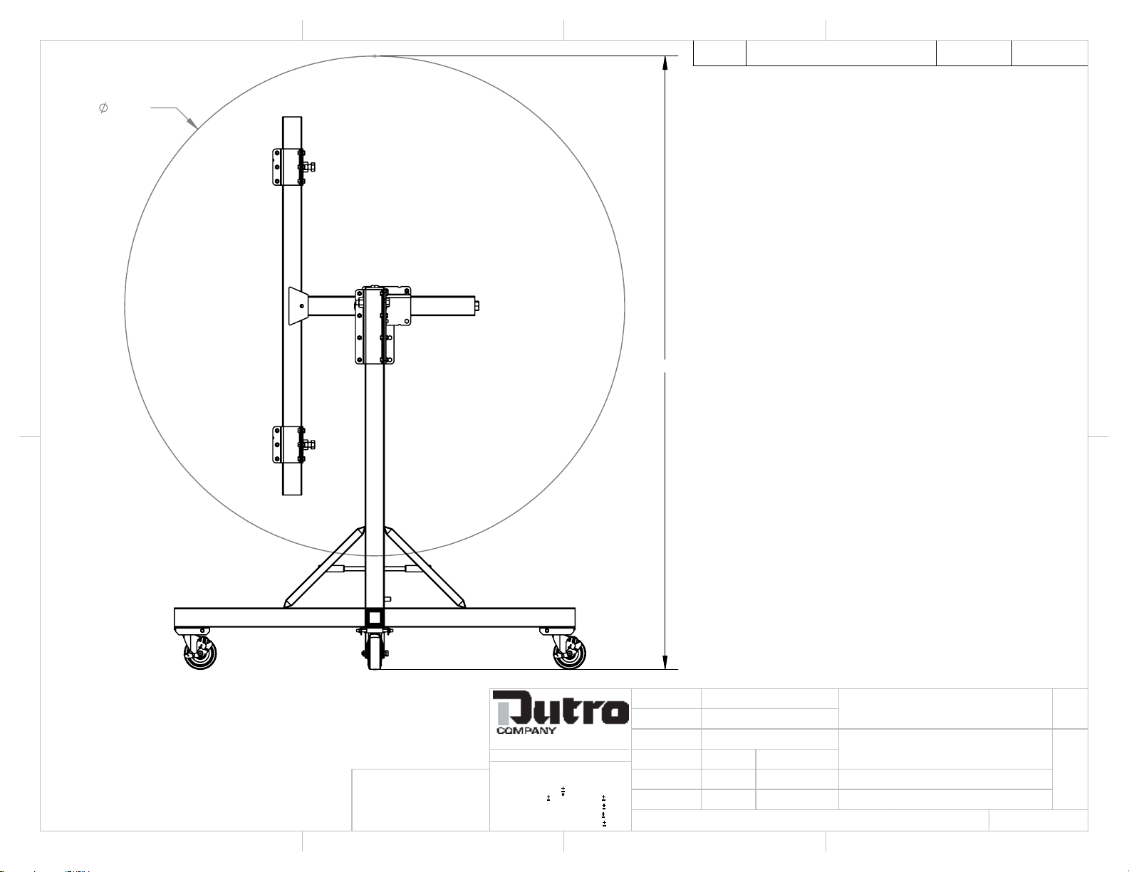
78.000
95.731
NOTE:
DIMENSIONS MAY VARY DEPENDING ON HEIGHT,
1.
WIDTH, & BALANCE CENTER OF VEHICLE.
REV.
DESCRIPTION
DATE
APPROVED
UNLESS OTHERWISE SPECIFIED:
DRAWN BY:
SIZE
CUSTOMER:
PROPRIETARY AND CONFIDENTIAL
FINISH:
DATE:
A
DIMENSIONS ARE IN INCHES
TOLERANCES:
FRACTIONAL:
1/32
ANGULAR:
.5
BEND
.03
ONE PLACE DECIMAL =
.1
TWO PLACE DECIMAL =
.03
THREE PLACE DECIMAL =
.005
MATERIAL:
DIR:
CHECKED BY:
THE INFORMATION CONTAINED IN THIS
DRAWING IS THE SOLE PROPERTY OF
DUTRO CO. ANY REPRODUCTION IN
PART OR AS A WHOLE WITHOUT THE
WRITTEN PERMISSION OF DUTRO CO.
IS PROHIBITED.
MODELED BY:
SHEET 1 OF 1
2
AUTO TWIRLER
DATE
:
DATE:
PROJECT NAME:
DWG:
AUTO TWIRLER ROTISSERIE
STANDARD COLOR
BHS
BHS
C:\CAD_FILES_VAULT\CAD FILES\AUTOTWIRLER\ROTISSERIES\
AT-PRO-90DEGREE
PRO ROTISSERIE
675 N 600W PHONE: 435-752-3921
LOGAN, UT 84321 FAX: 435-752-6360
UNLESS OTHERWISE SPECIFIED:
DRAWN BY:
SIZE
CUSTOMER:
PROPRIETARY AND CONFIDENTIAL
FINISH:
A
DIMENSIONS ARE IN INCHES
TOLERANCES:
FRACTIONAL:
1/32
ANGULAR:
.5
BEND
.03
ONE PLACE DECIMAL =
.1
TWO PLACE DECIMAL =
.03
THREE PLACE DECIMAL =
.005
MATERIAL:
DIR:
THE INFORMATION CONTAINED IN THIS
DRAWING IS THE SOLE PROPERTY OF
DUTRO CO. ANY REPRODUCTION IN
PART OR AS A WHOLE WITHOUT THE
WRITTEN PERMISSION OF DUTRO CO.
IS PROHIBITED.
MODELED BY:
SHEET 1 OF 1
B
2
DESCRIPTION:
PART#:
AT-PRO-AS
A
675 N 600W PHONE: 435-752-3921
LOGAN, UT 84321 FAX: 435-752-6360
1
1
3
4
A
3
4
B
REV
A
9/7/2017
STEEL
9/7/2017


