AutoVac VACUUM IQ C2000 Series User manual

DELTA Variable Frequency Drive
40HP X 1 460V
425-11082-DELTA

AutoVac - DELTA Variable Frequency Drive 40HP X 1 460V
OVERVIEW
This guide is to assist in the start up of
the C2000 series variable frequency
drives.
In Chapter 1:
The installation of the Variable Fre-
quency Drive will be covered.
In Chapter 2:
The input power to the package,
vacuum motor and pressure transdu-
cer connections will be shown.
In Chapter 3:
The operation of VFD display will be
covered.
In Chapter 4:
Will deal with electrical drawings for
different package configuration (mul-
tiple motors).
In Chapter 5:
Includes factory VFD parameters for
different package configurations.
Please take time to review this Guide
before proceeding with the installation
and testing.
QUICK START GUIDE FOR
USING THE C2000
SERIES VFD
VACUUM IQ
DANGER!
LETHAL VOLTAGES ARE PRE-
SENT Before applying power to
the variable frequency drive,
ensure that all protective covers
are on and all wiring connections
are secure. After the power has
been turned OFF, wait at least 5
minutes or until the display
indicator extinguishes complete-
ly before touching any wiring,
circuit boards or components.
02

Installation
• Please review and verify that the inverter was received free of damage and is the
correct size for the motor being used.
• To ensure personnel safety and to avoid equipment damage, follow standard
precautions and the installation procedures for mounting, wiring, and operating
environment.
Wiring
• Be sure to follow all applicable codes in make electrical connections to the motor
and input power terminals, as well as the control wiring.
• Transducer wiring should be run in a separate conduit.
• Transducer wiring should be run in a separate trench other than high voltage
wire trench if possible. Feedback errors may occur if transducer control wire is run
in the same trench with high voltage.
CHAPTER 1 -
INSTALLATION AND WIRING
NOTICE
AutoVac cannot be responsible for transducer feedback
errors due to control wire being run in the same trench
as the high voltage wire.
03
AutoVac - DELTA Variable Frequency Drive 40HP X 1 460V

With power OFF, ensure the following mechanical and electrical conditions:
• Rated output current of the VFD is equal or greater than the motor FLA.
• Supply voltage, VFD rated voltage and motor voltage match.
• Power factor correctio capacitors are NOT installed between the VFD and the
motor.
• Power factor correction capacitors are NOT installed within 100m (300ft) of input
to the VFD without a line reator.
• Motor and the load rotate freely.
To connect package to the power supply, motor and
pressure transducer please refer to picture below and
Auto Cad drawings submitted in Chapter 4.
CHAPTER 2 -
INPUT POWER, MOTOR AND
PRESSURE TRANSDUCER
CONNECTIONS.
04
Input power
connection L1, L2
L3, Gnd
Transducer
Connection
Motor Connection
T1,T2, T3, Gnd
AutoVac - DELTA Variable Frequency Drive 40HP X 1 460V

NOTE
For single motor configuration, input power and transducer connections are
the same. Motor connection terminals are labelled 1T1, 1T2 and 1T3.
CAUTION
To prevent an electric shock always ground the motor and VFD. Use indepen-
dent grounding method for the VFD. If independent grounding is impossible
use common grounding as shown on the figure below.
05
Inverter Inverter
Other
equipment
Other
equipment
AutoVac - DELTA Variable Frequency Drive 40HP X 1 460V

VFD is supplied with KPC-CC01 keypad. Next chapter will explain basic KPC-CC01
operation.
Descriptions of keypad Functions
Key Descriptions
Start Operation Key
1. It is only valid when the source of operation command is from the keypad.
2. It can operate the AC motor drive by the function setting and the RUN
LED will be ON.
3. It can be pressed again at stop process.
KPC-CC01
Communication Interface
RJ45 (socket), RS-485 interface
Installation Method
1. Embedded type and can be put flat on the
surface of the control box. The front cover
is water proof.
2. Buy a MKC-KPPK model to do wall moun-
ting or embedded mounting. It’s protec-
tion level is IP66.
3. The maximum RJ45 extension lead is 5m
(16ft).
4. This keypad can only be uesed on Delta’s
motor drive C2000, CH2000 and CP2000.
CHAPTER 3 -
VFD DISPLAY OPERATION
06
Operation Direction Key
1. This key only controls the operation direction, and will NOT activate the
drive. FWD: forward, REV: reverse.
2. Refer to the LED descriptions for more details.
ENTER Key
Press ENTER and go to the next level. If it is the last level then press ENTER to
execute the command.
a. Because the condition which triggers the fault is not cleared. When
the condition is cleared, the fault can be reset.
b. Because it’s the fault status checking when power-on. When the
condition is cleared, re-power again, and the fault can be reset.
RUN
STOP
RESET
FWD
REV
ENTER
Stop Command Key. This key has the highest priority in any situation.
1. When it receives STOP command, no matter if the AC motor drive is in
operation or stop status, the AC motor drive needs to execute “STOP”
command.
2. The RESET key can be used to reset the drive after the fault occurs.
3. The reasons why the error cannot be reset:
F1 F2 F3 F4
ESC MENU
HAND AUTO
ENTER
RUN FWD
REV
STOP
RESET
AutoVac - DELTA Variable Frequency Drive 40HP X 1 460V

07
ESC Key
ESC Key function is to leave current menu and return to the last menu. It also
functions as a return key or cancel key in the sub-menu.
Key Descriptions
Press menu to return to main menu.
Menu content:
Function Key
1. The function keys have factory settings and can be defined by users. The
factory settings of F1 and F4 work with the function list below. For exam-
ple, F1 is JOG function, F4 is a speed setting key for adding/deleting user
defined parameters.
2. Other functions must be defined by TPEditor firts (please use version 1.60
or above). TPEditor software can be download at:
Direction: Left / Right / Up / Down
1. In the numeric value setting mode, it is used to move the cursor and
change the numeric value.
2. In the menu/text selection mode, it is used for item selection.
1. Parameter Setup
2. Quick Start
3. Application Selection List
4. Changed List
5. Copy Parameter
6. Fault Record
7.
8.
9.
10.
11.
12.
Language Setup
Time Setup
Keypad Locked
PLC Function
Copy PLC
Display Setup
13.
14.
15.
16.
Startup Menu
Main Page
PC Link
Start Wizard
HAND Key
1. This key is executed by the parameter settings of the source of Hand
frequency and hand operation. The factory settings of both of Hand
frequency and hand operation are the digital keypad.
2. Press HAND key at stop status, the setting will switch to hand frequency
source and hand operation source. Press HAND key at operation status, it
stops the AC motor drive first (diplay AHSP warning), and switch to hand
frequency source and hand operation source.
3. KPC-CC01 display HAND mode on the screen.
AUTO Key
1. This key is executed by the parameter settings of the source of AUTO
frequency and AUTO operation. The factory setting is the external terminal
(source of operation is 4˜20mA).
2. Press Auto key at stop status, the setting will switch to hand frequency
source and hand operation source. Press Auto key at operation status, it
stops the AC motor drive first (diplay AHSP warning), and switch to auto
frequency source and auto operation source.
3. KPC-CC01 display AUTO mode on the screen.
ESC
MENU
HAND
AUTO
F1 F2
F3 F4
http://www.deltaww.com/services/DownloadCenter2.aspx?secI-
D=8&pid=2&tid=0&CID=060302&typeID=1&downloadID=,&tittle=--Selec
Product Series --&dataType=8;&check=1&hl=en-US
Please refer to instruction for TPEditor in Chapter 10-3.
AutoVac - DELTA Variable Frequency Drive 40HP X 1 460V
08
Descriptions of keypad Functions
Function of Digital Keypad KPC-CC01
POWER ON
LED Descriptions
Steady ON: operation indicator of the AC motor drive, including DC brake, zero
speed, standby, restart after fault and speed search.
Blinking: drive us decelerating to stop or in the status of base block.
Steady OFF: drive doesn’t execute the operation command.
Steady ON: stop indicator of the AC motor drive.
Blinking: drive is in the standby status.
Steady OFF: drive doesn’t execute “STOP” command.
1. The default Start-up page is Delta Logo. (Default 1
and 2).
2. User can customize their start-up page through the
edited function. (Need to purchase the optional
accesories).
The top line of LCD display the status of drive.
After main menu is selected, the start-up page will
display in the format user defined. The page sjown
on the left is displayed as Delta default setting.
The bottom line of LCD display time and JOG.
Operation Direction LED under Torque Mode
1. Green light is ON: when the torque command >0, and the motor is
running forward.
2. Red light is ON: when the torque command < 0, and the motor is running
backward.
3. Twinkling light: when the torque command < 0, and the motor is running
forward.
Start-up
Skip to main page
after 3 sec.
60.00 Hz
0.00 Hz
540.0 Vdc
JOG 14:35:56
AUTO
F
H
V
60.00 Hz
0.00 Hz
540.0 Vdc
JOG 14:35:56
Press once
Press
F
H
V
60.00 Hz
0.00 Hz
540.0 Vdc
JOG 14:35:56
AUTO
F
H
V
0.00 Hz
540.00 Vdc
0.0 Amp
JOG 14:35:56
AUTO
H
V
A
MENU
Press again Press again
RUN
STOP
RESET
FWD
REV
AutoVac - DELTA Variable Frequency Drive 40HP X 1 460V

09
Display Icon
Display Item
Parameter Setup
Press
For example: Setup source of master frequency command.
Once in the Group 00 Motor Drive
Parameter, use Up/Down key to select
parameter 20: Auto Frequency Com-
mand.
to select.
1: Pr Setup
2: Quick Start
3: App Sel List
MENU
MENU
1: Parameter Setup
2: Quick Start
3: Application
Selection List
4. Changed List
5: Copy Parameter
6: Fault Record
7: Language Setup
8: Time Setup
9: Keypad Locked
10: PLC Function
11: Copy PLC
12: Display Setup
13: Startup Menu
14: Main Page
15: PC Link
16: Start Wizard
1: Default 1
2: Default 2
3: User define
Start-up
00: SYSTEM PAR
01: BASIC PARA
02: DIGITAL IN/
Pr Setup
00: SYSTEM PAR
01: BASIC PARA
02: DIGITAL IN/
Pr Setup
00: Identity Co
01: Rated Curren
02: Parameter Re
00-SYSTEM PARAME
When this parameter is selected, pres
ENTER key to go to this parameter’s
setting menu.
20: Source of F
21: Source of OP
22: Stop Methods
00-SYSTEM PARAME
Use Up/Down key to choose a setting.
For example: Choose “2 Analogue
input”, the press the ENTER key.
2
Analog input
0˜8ADD
00-20
: present setting
: roll down the page for more options
: show complete sentence
Press for more options
Press
Once a parameter group is
selected,
to select a parameter
group.
Press for complete information
ENTER
Press to go into that
group.
ENTER
AutoVac - DELTA Variable Frequency Drive 40HP X 1 460V

10
Language Setup
Language setting option is displayed in the language of the
user’s choice. Language setting options:
Use Up/Down key to select
language, than press ENTER.
English
繁体中文
1.
2.
简体中文
Türkçe
3.
4.
Русский
Español
Português5.
6. Français
7.
8.
After pressing the ENTER key, a END
will be displayed which means that
the parameter setting is done.
NOTE: When parameter
lock/password protection function is
enabled, it will display “Pr. lock” on the
right-up corner of the keypad.
The parameter cannot be written or is
protected by the password under this
circumstances.
END
Analog input
00-20
2
Analog input
00-20 Pr. lock
0˜8ADD
1: English
Language
2: 繁体中文
3:简体中文
Language Setup
Use Left/Right key to select
Year, Month, Day, Hour, Minute
or Second to set up
Use Up/Down key to
set up Year
Use Up/Down key to
set up Month
Use Up/Down key to
set up Day
2009/01/01
_ _ : _ _ : _ _
Time setup
2014/01/01
00 : 00 : 00
Time setup
2014/01/01
00 : 00 : 00
Time setup
2014/01/01
00 : 00 : 00
Time setup
Use Up/Down key to
set up Hour
2014/01/01
21 : 00 : 00
Time setup
Use Up/Down key to
set up Minute
2014/01/01
21 : 12 : 00
Time setup
Use Up/Down key to
set up Second
2014/01/01
21 : 12 : 14
Time setup
AutoVac - DELTA Variable Frequency Drive 40HP X 1 460V

11
NOTE:
Limitation: The charging process of the super capacitor will
finish in about 6 minutes. When the digital keypad is
removed, the time setting will be in stanby status for 7
days. After this period, the time need to be reset.
After setting up, press ENTER to
confirm the setup.
END
Time setup
AutoVac - DELTA Variable Frequency Drive 40HP X 1 460V

12
CHAPTER 4 -
AutoCad DRAWINGS
TERMINAL CONNECTION
Case 1 - Single motor
AutoVac - DELTA Variable Frequency Drive 40HP X 1 460V
13
In this page you can view the wiring connections for the four possible options of
pressure transducer sensor.
Please follow the pictures to ensure a proper connection.
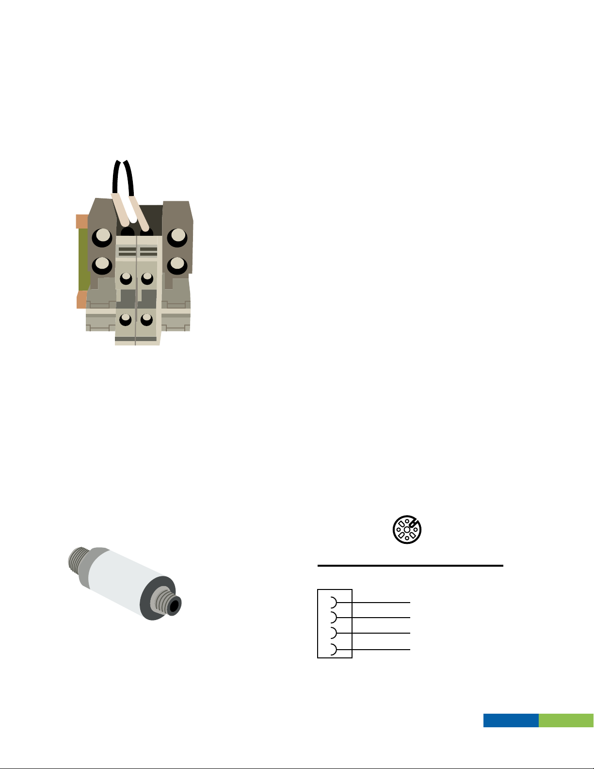
Transducer sensor wiring connections
Cordset Wiring
Brand: Turck
Part No.: PT01VR-11-LI3-H1131
Turck Sensor Connector A
Circuit Diagram VFD TERMINAL
1
2
3
4
Brown +10V
N.C.
AV1
N.C.
White
Blue
Black
1
3
24
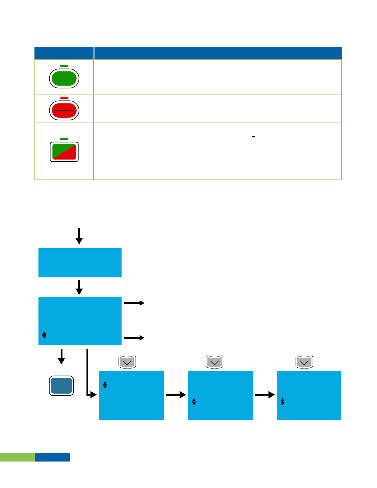
The enclosure has a dedicated terminal block to
wire the transducer sensor; please look up for the
terminal block aside of the Motor Connection
Terminal Block.
Terminal Block
There are two wires: brown and white; brown is
for the transducer power supply (+10V) and the
white is the Analog Input to the VFD (AV1).
Delta VFD Enclosure
AutoVac - DELTA Variable Frequency Drive 40HP X 1 460V
14
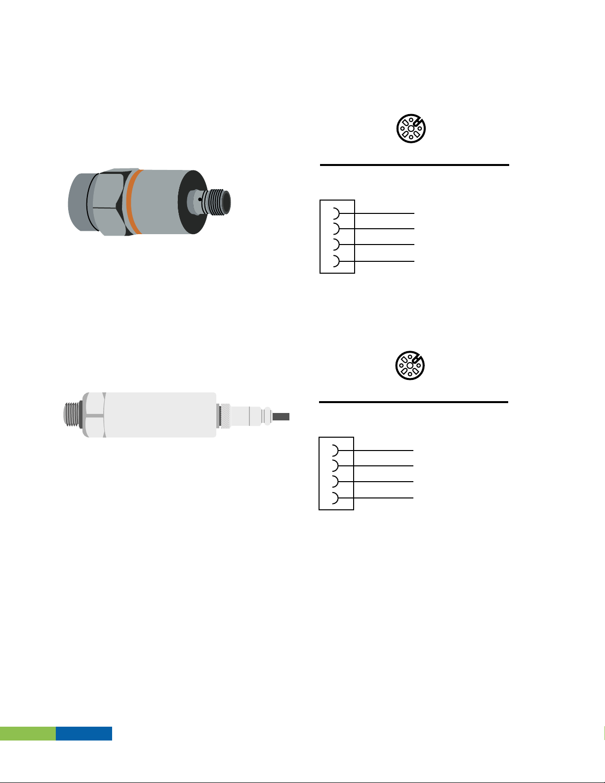
Cordset Wiring
Connector A
Circuit Diagram VFD TERMINAL
1
2
3
4
Brown +10V
AV1
N.C.
N.C.
White
Blue
Black
1
3
24
Brand: IFM
Part No.: PA3029
Brand: LEFOO
Part No.: LFT2010
Connector A
Circuit Diagram VFD TERMINAL
1
2
3
4
Brown +10V
N.C.
AV1
N.C.
White
Blue
Black
1
3
24
AutoVac - DELTA Variable Frequency Drive 40HP X 1 460V

15
CHAPTER 5 -
VFD Parameter Settings
5.1 - VFD Parameter Settings for Single motor configuration
The Variable Frequency Drives are shipped with the parameter values shown in
Parameter Tables and no further programming should be necessary. However, if
additional fine tuning is required please refer to Chapter 3, VFD Display Opera-
tion.
Autovac Settings - Single VFD
Parameter Parameter Description Setting
Maximum frequency 60 Hz
35 Hz
30 sec
30 sec
0
1
52
3599
2
33.8
2
01-00
01-07
01-12
01-13
00-22
03-00
05-01
05-03
05-04
05-05
07-06
Minimum frequency
Acceleration time
Deceleration time
Stop selection
Analog input selection (AVI)
Full-load current for induction motor 1 (A)
Rated speed for induction motor 1 (rpm)
Number of poles for induction motor 1
No-load current for induction motor 1 (A)
Restart after momentary power loss
AutoVac - DELTA Variable Frequency Drive 40HP X 1 460V

DELTA Variable Frequency Drive
40HP X 1 460V
425-11082-DELTA
Table of contents
Other AutoVac Servo Drive manuals

Popular Servo Drive manuals by other brands


Danfoss
Danfoss VLT AQUA Drive FC 200 Programming guide

GEZE
GEZE E 170/230 V AC Wiring diagram

Stober
Stober SC6 Series operating manual

Lenze
Lenze L-force EYP Series Mounting instructions

LAFERT
LAFERT ATE ZONE 2-22 operating instructions

Rockwell Automation
Rockwell Automation Allen-Bradley Kinetix 3 2071-AP0 user manual