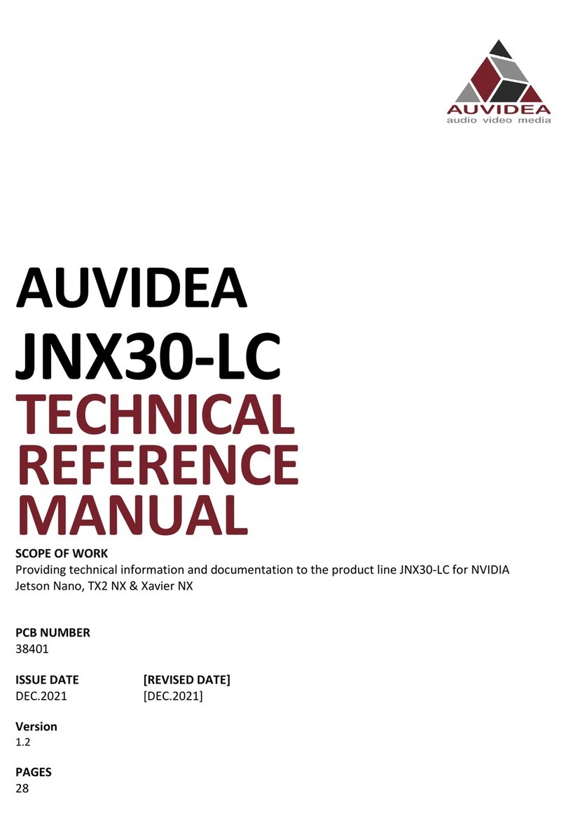
Auvidea JNX30D Use and care manual

AUVIDEA
JNX30D
TECHNICAL
REFERENCE
MANUAL
SCOPE OF WORK
Providing technical information and documentation to the product line JNX30D for Nvidia
Jetson Nano & NX
REPORT NUMBER
38486
ISSUE DATE [REVISED DATE]
DEC.2021 [DEC.2021]
Version
1.0
PAGES
19

TECHNICAL REFERENCE MANUAL
CONTENTS
SECTION 1 COPYRIGHT NOTICE ...................................................................................... 4
SECTION 2 OVERVIEW ................................................................................................... 5
2.1 Jetson Nano ................................................................................................................................................. 5
2.2 JNX30D ......................................................................................................................................................... 5
2.3 Applications ................................................................................................................................................. 5
2.4 JNX30D features and comparison ............................................................................................................... 5
2.5 Technical specifications ............................................................................................................................... 6
2.6 Model pictures ............................................................................................................................................. 7
2.7 Power consumption .................................................................................................................................... 7
2.8 Options ........................................................................................................................................................ 7
SECTION 3 FEATURES ..................................................................................................... 8
3.1 GPIO-Header ................................................................................................................................................ 8
3.2 Crypto chip .................................................................................................................................................. 8
3.3 MCU 8
SECTION 4 PINOUT DESCRIPTION .................................................................................. 9
4.1 J1 - Power input jack .................................................................................................................................... 9
4.2 J3 - Ethernet ................................................................................................................................................ 9
4.3 J4 - M.2 ........................................................................................................................................................ 9
4.4 J5 - CSI-2 CD ................................................................................................................................................. 9
4.5 J8 - USB-2 ................................................................................................................................................... 10
4.6 J9 - HDMI ................................................................................................................................................... 10
4.7 J10 - CSI-2 AB ............................................................................................................................................. 10
4.8 J11 - USB 3.0 – 3.1 ..................................................................................................................................... 11
4.9 J12 - Micro USB .......................................................................................................................................... 11
4.10 J13 - CAN .................................................................................................................................................... 11
4.11 J14 - UART connector ................................................................................................................................ 12
4.12 J22 - Reset Button ...................................................................................................................................... 12
4.13 J32 - Button and LED header ..................................................................................................................... 12
4.14 J36 - Fan connector ................................................................................................................................... 13
4.15 P11 - PoE connector .................................................................................................................................. 13
4.16 P12 - GPIO header ..................................................................................................................................... 13
4.17 U10 - Crypto chip ....................................................................................................................................... 14
4.18 LED - Eth .................................................................................................................................................... 15
4.19 LED - Over current ..................................................................................................................................... 15
4.20 LED - PWR .................................................................................................................................................. 15
4.21 Micro SD-card reader ................................................................................................................................ 15
SECTION 5 REVISIONS AND CHANGES .......................................................................... 16
5.1 Rev 1 .......................................................................................................................................................... 16
SECTION 6 FAQ ............................................................................................................ 17

JNX30D TECHNICAL REFERENCE MANUAL
VERSION: 1.0 Page 3 of 19 DEC 2021
SECTION 7 DISCLAIMER ............................................................................................... 18

JNX30D TECHNICAL REFERENCE MANUAL
VERSION: 1.0 Page 4 of 19 DEC 2021
SECTION 1
COPYRIGHT NOTICE
Trademarks
NVIDIA, the NVIDIA logo, CUDA, Jetson, Maxwell, Tegra, Nano and VisionWorks are registered
trademarks and/or trademarks of NVIDIA Corporation in the United States and other countries.
Other company and product names may be trademarks of the respective companies with which they
are associated.
© Auvidea GmbH 2021
All Rights Reserved
No part of this document or any of its contents may be reproduced, copied, modified or adapted,
without the prior written consent of the author, unless otherwise indicated for stand-alone
materials.
You may share this document by any of the following means: this PDF file may be distributed freely if
no changes or modifications to the document are made.
For any other mode of sharing, please contact the author at the email below. [email protected]
Commercial use and distribution of the contents of this document is not allowed without express and
prior written consent of Auvidea GmbH.

JNX30D TECHNICAL REFERENCE MANUAL
VERSION: 1.0 Page 5 of 19 DEC 2021
SECTION 2
OVERVIEW
2.1 Jetson Nano
This new JNX30D carrier board turns the Jetson Nano compute module into a super mini computer.
The Nano offers very high computational (quad core ARM® Cortex®-A57 with up to 1.43 GHz) and
graphical (NVIDIA Maxwell™ with 128 CUDA cores)
processing performance in a tiny form factor.
2.2 JNX30D
§ Easy aluminum case integration
§ Easy flashing: just connect a USB OTG cable
§ High performance storage: M.2 NVME PCIe x4
§ 2 versions support either Nano dev kit module (with SD card - 38346-3) or Nano production
module (with eMMC - 38346-4)
2.3 Applications
§ Industrial AI computers
§ Digital signage systems
2.4 JNX30D features and comparison
Description
JNX30D
Nvidia Devkit
Power
6V - 19V (barrel connector)
5V – 19V
NX powering
5V 8A power supply
?
DP
no
yes
HDMI
yes
yes
Fan connector
yes
yes
M.2 NVME Key M
yes
yes
Micro-SD card
yes
no
M.2 Key E
only with external module
(using internal USB - J8)
yes
CAN RX / TX
yes
yes
USB 3.0
1x USB 3.1
(Native - full performance)
4x USB 3.1
(Via USB hub - shared)
Micro USB
1x Micro USB
(Host and device mode)
1x Micro USB
(Device mode only)
Auto Flashing
yes
(Plug in host cable and flash)
no
USB 2.0
1x USB 2.0 (JST-GH, J8)
no
Ethernet
Gigabit RJ45 (one LED)
Gigabit RJ45 (2 LEDs)
PoE option
yes - P11
yes - J19
CSI
2x CSI-2 plus camera LED
(Hardware sync available)
2x CSI-2

JNX30D TECHNICAL REFERENCE MANUAL
VERSION: 1.0 Page 6 of 19 DEC 2021
2.5 Technical specifications
Description
Note
HDMI
USB 3.1
Physical size
Mounting holes
Temperature range
Humidity
Longevity
UART
2x (J14) plus 1x 40 pin header
40 pin header
I2C
2x (40 pin header)
2x (40 pin header)
I2S
40 pin header
(5V tolerant, unidirectional)
40 pin header
SPI
2x (40 pin header)
(5V tolerant, unidirectional)
2x (40 pin header)
GPIO
3x in + 3x out (40 pin header)
(5V tolerant, unidirectional)
6x bi-dir (40 pin header)
Additional features
Protection
overvoltage protection (TVS diode)
?
Level shifters
unidirectional level shifters (work better)
bi-rectional (sometimes
cause problems)
Buttons
8 pin header
12 pin header
Expandability :
1. Fully populated variants available
no
2. Add-on boards for more USB and
Ethernet
3. IMU
4. Board EEPROM and crypto chip (for SW
copy protection)
5. PCIe x1 connector
6. LM823 WIFI module
7. 2 more CSI-2 interfaces (2 lanes each)
8. Micro SD card
9. RTC battery (rechargeable)
10. Over current fuse (product safety)
11. UPS option for graceful power down
12. On board MCU for watchdog and
remote power cycle (LTE)

JNX30D TECHNICAL REFERENCE MANUAL
VERSION: 1.0 Page 7 of 19 DEC 2021
2.6 Model pictures
2.7 Power consumption
Description
X221-LC (Rev 2)
Carrier board logic
>90%
1.8/3.3/5V power converter
efficiency
-
Power in converter efficiency
>90%
2.8 Options
Flexible design and manufacturing
§ designed and manufactured in Germany
§ in-house fully automated production line with 3D AOI
§ special configuration possible with minimum purchase of 25 pcs (display port, M.2, PoE, 48V
power in, super cap option, 2 RPi camera module connectors, SPI, I2C, switches, etc.)
§ design services: you architect your custom carrier board and Auvidea designs and produces it
- please ask for a quote
Top side
Bottom side
JNX30D

JNX30D TECHNICAL REFERENCE MANUAL
VERSION: 1.0 Page 8 of 19 DEC 2021
SECTION 3
FEATURES
3.1 GPIO-Header
3.2 Crypto chip
3.3 MCU

JNX30D TECHNICAL REFERENCE MANUAL
VERSION: 1.0 Page 9 of 19 DEC 2021
SECTION 4
PINOUT DESCRIPTION
4.1 J1 - Power input jack
Nexus
Reverse voltage protection also functions as back power protection if PoE injection is used with J32
pin 2.
4.2 J3 - Ethernet
Standard pinout with PoE capable magnetics class 3 and 4.
4.3 J4 - M.2 PCIEx4/x1/USB/UART/I2C/GPIO
DF17(3.0)-80DS-0.5V (57)
With activity LED above the J10 connector.
PCIex4.
M3 mounting screw required.
M.2 modules need to be slip in and cannot be lowered in as it would collide with the Jetson module
holder.
4.4 J5 - CSI-2 CD
Pin
Description
Note
1
12V
Reverse voltage protection, over voltage protection (SMA6J18A/CA) with
max 20V peak
2
GND
Pin
Description
Socket pin
Note
1
2
GEN1_I2C_SDA
187
3
GEN1_I2C_SCL
185
4
GND
5
CAM2—MCLK
6
CAM2_PWDN
152
Default PWM controlled (can cause problems with certain
cameras as they are quickly turned off and on the whole
time).
Enable/disable signal possible with device tree changes.
Can also be used to synchronise CSI-2 cameras as this pin is
connected to all CSI-2 ports.
7
GND
8
CSI_D_D1_P
66
9
CSI_D_D1_N
64

JNX30D TECHNICAL REFERENCE MANUAL
VERSION: 1.0 Page 10 of 19 DEC 2021
Every CSI camera uses its own I2C bus lanes
4.5 J8 - USB-2
4.6 J9 - HDMI
Standard pinout
CEC is not supported (pin 13 of HDMI connector)
Power pin 18 is current limited by PTC fuse (5V, 50mA)
4.7 J10 - CSI-2 AB
JST-GH 1.25mm
10
GND
11
CSI_D_D0_P
42
12
CSI_D_D0_N
40
13
GND
14
CSI_C_CLK_P
54
15
CSI_C_CLK_N
52
16
GND
17
CSI_C_D1_P
60
18
CSI_C_D1_N
58
19
GND
20
CSI_C_D0_P
48
21
CSI_C_D0_N
46
22
GND
Pin
Description
Socket pin
Note
1
5V
2
USB2_D_N
121
3
USB2_D_P
123
4
GND
Pin
Description
Socket pin
Note
1
2
CAM-I2C_SDA
215
3
CAM-I2C_SCL
213
4
GND
5
CAM1—MCLK
6
CAM1_PWDN
206
Default PWM controlled (can cause problems with certain
cameras as they are quickly turned off and on the whole
time).
Enable/disable signal possible with device tree changes.
Can also be used to synchronise CSI-2 cameras as this pin is
connected to all CSI-2 ports.

JNX30D TECHNICAL REFERENCE MANUAL
VERSION: 1.0 Page 11 of 19 DEC 2021
Every CSI camera uses its own I2C bus lanes
4.8 J11 - USB 3.0 – 3.1
USB Typ A standard pinout
In Rev 1: power control is always on, 5V 1A
In Rev 2 and up: Controllable with GPIO pin 126 power on[0]/off[1] (default on[0]), 5V 1A
4.9 J12 - Micro USB
Standard pinout
OTG support
500mA 5V usable with device tree changes to power external devices, enable power control with
GPIO_02 (Socket pin: 124)
4.10 J13 – CAN
JST-GH 1.25mm
CAN can only be used with Jetson Nano NX and TX2 NX, these pins are reserved with the Nano.
Direct connection to module with no further protection!
7
GND
8
CSI_B_D1_P
17
9
CSI_B_D1_N
15
10
GND
11
CSI_B_D0_P
5
12
CSI_B_D0_N
3
13
GND
14
CSI_A_CLK_P
12
15
CSI_A_CLK_N
10
16
GND
17
CSI_A_D1_P
18
18
CSI_A_D1_N
16
19
GND
20
CSI_A_D0_P
6
21
CSI_A_D0_N
4
22
GND
Pin
Description
Socket pin
Note
1
5V
2
CAN_TX
145
3
CAN_RX
143
4
GND

JNX30D TECHNICAL REFERENCE MANUAL
VERSION: 1.0 Page 12 of 19 DEC 2021
4.11 J14 - UART connector
JST-GH 1.25mm
Unidirectional
4.12 J22 - Reset Button
To reset the compute module
4.13 J32 - Button and LED header
Pin
Description
Socket pin
Note
1
5V
2
UART0_TXD
99
3.3V
3
UART0_RXD
101
3.3V
4
UART2_TXD
236
3.3V, Debug port
5
UART2_RXD
238
3.3V, Debug port
6
GND
Pin
Description
Socket pin
Note
1
CAM_LED
218
CAM_LED signal turned high if J5 pin 5 and/or J10 pin 5
and/or GPIO pin 218 (default: off[1]) is high.
CAM_LED flash signal can be used to control external status
cam LED. When using external LED pleas limit current with
external resistor. Connect cathode to this pin and anode to
5V or 12V power. Max 2A
2
12V
Connection to internal power rail (PoE power injection
possible with additional PoE module)
3
BTN PWR ON
-
default: auto power on, no function in Ref 1 (devkit version)
4
Vdd RTC
235
Real time clock
5
SYS RST IN
239
1.8V
6
GPIO_PA6
178
1.8V
7
Force recovery
214
1.8V input, open drain
8
GND

JNX30D TECHNICAL REFERENCE MANUAL
VERSION: 1.0 Page 13 of 19 DEC 2021
4.14 J36 - Fan connector
Picoblade 1.5mm
4.15 P11 - PoE connector
This connects to the 4 centre pins of the ethernet magnetics on the cable side to extract ore inject
PoE power
This connector may be used for PoE addon solutions
4.16 P12 - GPIO header
Pin
Description
Socket pin
Note
1
GND
2
5V
Max. 1A
3
TACH
-
Not connected
4
PWM
230
Pin
Description
Socket pin
Note
1
3.3V
2
5V
3
I2C1_SDA
189
3.3V, GEN2_I2C_SDA
4
5V
5
I2C1_SCL
189
3.3V, GEN2_I2C_SCL
6
GND
7
GPIO09_LS
211
IN
8
UART1_TXD_LS
203
IN
9
GND
10
UART1_RXD_LS
205
OUT
11
UART1_RTS_LS
207
IN
12
I2S0_SCLK_LS
199
IN
13
SPI1_SCK_LS
106
IN
14
GND
15
GPIO12_LS
218
IN

JNX30D TECHNICAL REFERENCE MANUAL
VERSION: 1.0 Page 14 of 19 DEC 2021
Please use any Raspberry Pi modules with care and carefully check compatibility as compatibility was
in mind but cannot be guaranteed for all modules.
Output levels are 3.3V.
All GPIO headers are unidirectional.
4.17 U10 - Crypto chip
Model ATSHA204A
Integrated for software protection and licensing.
Datasheet Link:
https://ww1.microchip.com/downloads/en/DeviceDoc/ATSHA204A-Data-Sheet-40002025A.pdf
16
SPI1_CS1_LS
112
IN
17
3.3V
18
SPI1_CS0_LS
110
IN
19
SPI0_MOSI_LS
89
IN
20
GND
21
SPI0_MISO_LS
93
OUT
22
SPI1_MISO_LS
108
OUT
23
SPI0_SCK_LS
91
OUT
24
SPI0_CS0_LS
95
IN
25
GND
26
SPI0_CS1_LS
97
IN
27
ID_I2C_SDA
187
3.3V, GEN1_I2C_SDA
28
ID_I2C_SCL
185
3.3V, GEN1_I2C_SCL
29
GPIO01_LS
118
OUT
30
GND
31
GPIO11_LS
216
OUT
32
GIIO07_LS
206
IN
33
GPIO13_LS
228
OUT
34
GND
35
I2S0_LRCK_LS
197
IN
36
UART1_CTS_LS
209
OUT
37
SPI1_MOSI_LS
197
IN
38
I2S0_SDIN_LS
195
OUT
39
GND
40
I2S0_SDOUT_LS
193
IN
Pin
Description
Socket pin
Note
1
NC
2
NC
3
NC
4
GND
5
GEN3_I2C_SDA
6
GEN3_I2C_SCL
7
NC
8
3.3V

JNX30D TECHNICAL REFERENCE MANUAL
VERSION: 1.0 Page 15 of 19 DEC 2021
4.18 LED - Eth
Shows Ethernet activity on Socket pin 194 - on[0]/off[1], default: off
At own risk resistor can be moved to control Eth-LED via socket pin 188 (link LED)
4.19 LED - Over current
Placed between J1 (Power connector) and J3 (Ethernet).
Shows over current of integrated 5V power supply. If 8A is acceded the power output is disabled, and
the LED is activated to red. To reset this over current condition power input must be cycled.
The 5V power supply mainly powers the 5V compute module, USB ports and the 3.3V power
controller for the M.2 socket.
4.20 LED - PWR
GPIO pin 178 on[1]/off[0], default: off[0]
4.21 Micro SD-card reader
Standard pinout.
Needs device tree changes to be activated which includes enabling Socket pin 211.

JNX30D TECHNICAL REFERENCE MANUAL
VERSION: 1.0 Page 16 of 19 DEC 2021
SECTION 5
REVISIONS AND CHANGES
5.1 Rev 1

JNX30D TECHNICAL REFERENCE MANUAL
VERSION: 1.0 Page 17 of 19 DEC 2021
SECTION 6
FAQ
To be added.

JNX30D TECHNICAL REFERENCE MANUAL
VERSION: 1.0 Page 18 of 19 DEC 2021
SECTION 7
DISCLAIMER
Thank you for reading this manual. If you have found any typos or errors in this document, please let
us know.
This is the preliminary version of this data sheet. Please treat all specifications with caution as there
may be any typos or errors.
The Auvidea Team

JNX30D TECHNICAL REFERENCE MANUAL
VERSION: 1.0 Page 19 of 19 DEC 2021
End of dokument
Other manuals for JNX30D
1
Table of contents
Other Auvidea Computer Hardware manuals
Popular Computer Hardware manuals by other brands

Cypress Semiconductor
Cypress Semiconductor STK16C88 user manual

Rane
Rane CP66 installation manual

Advantage Controls
Advantage Controls NANO-N manual

Thermaltake
Thermaltake V3 Black Edition VL8000 Series user manual

National Instruments
National Instruments MXI Express x4 instruction manual

Pickering
Pickering 60-901 user manual