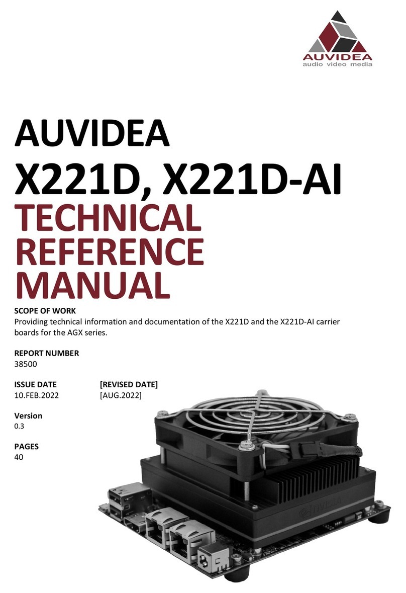
Auvidea X221 Product manual

AUVIDEA
X221, -LC, -AI
TECHNICAL
REFERENCE
MANUAL
SCOPE OF WORK
Providing technical information and documentation for the X221, -LC, -AI carrier boards for
the AGX Xavier
REPORT NUMBER
38413
ISSUE DATE [REVISED DATE]
16.NOV.2021 [FEB.2021]
Version
1.4
PAGES
38

X221, -LC, -AI
TECHNICAL REFERENCE MANUAL
VERSION: 1.4
Page 2 of 38
FEB.2021
CONTENTS
SECTION 1 Document revisions and changes ............................................................. 4
SECTION 2 Product revisions and changes ................................................................. 5
SECTION 3 Overview ................................................................................................. 6
3.1 Model comparison....................................................................................................................................... 6
3.2 Technical specification................................................................................................................................. 7
3.3 Model pictures............................................................................................................................................. 8
3.4 Power consumption..................................................................................................................................... 9
SECTION 4 Features..................................................................................................10
4.1 Crypto authentication chip ........................................................................................................................ 10
4.2 Safety MCU ................................................................................................................................................ 10
SECTION 5 Pinout description...................................................................................13
5.1 J2 - POWER PORT....................................................................................................................................... 13
5.2 J4 - Ethernet............................................................................................................................................... 13
5.3 J5 - MCU UART ........................................................................................................................................... 13
5.4 J6 - CAN1 .................................................................................................................................................... 13
5.5 J7 - I2C........................................................................................................................................................ 13
5.6 J8 - FAN ...................................................................................................................................................... 14
5.7 J10 - Debug ................................................................................................................................................ 14
5.8 J11 - HDMI.................................................................................................................................................. 14
5.9 J12 - CAN0 .................................................................................................................................................. 14
5.10 J14 - MCU................................................................................................................................................... 15
5.11 J15 - 2x USB 3.1.......................................................................................................................................... 15
5.12 J17 - MICRO USB ........................................................................................................................................ 16
5.13 J18 – Wi-Fi.................................................................................................................................................. 16
5.14 J19 - SUPER CAP UPS.................................................................................................................................. 16
5.15 J20 - PCIEx4/x1/USB/UART/I2C/GPIO ........................................................................................................ 16
5.16 J21 - POWER BUTTON ................................................................................................................................ 18
5.17 J22 - ETHERNET.......................................................................................................................................... 18
5.18 J23 - I2S/I2C ............................................................................................................................................... 18
5.19 J25 - FORCE RECOVERY BUTTON................................................................................................................ 18
5.20 J26 - RESET BUTTON .................................................................................................................................. 18
5.21 J27 - MICRO SD-CARD/UFS SLOT ............................................................................................................... 19
5.22 J28 - CSI-2................................................................................................................................................... 19
5.23 J29 - USB 2.0 .............................................................................................................................................. 21
5.24 J31 - POWER OUT....................................................................................................................................... 21
5.25 J32 – USB(3) ............................................................................................................................................... 21
5.26 J33 – USB(2) ............................................................................................................................................... 22
5.27 J34 – USB(1) ............................................................................................................................................... 22
5.28 J35 - POWER OUT....................................................................................................................................... 22
5.29 J36 - I2S2 .................................................................................................................................................... 22

X221, -LC, -AI
TECHNICAL REFERENCE MANUAL
VERSION: 1.4
Page 3 of 38
FEB.2021
5.1 RGB LED ..................................................................................................................................................... 22
SECTION 6 FAQ ........................................................................................................23
SECTION 7 Disclaimer...............................................................................................24
SECTION 8 Copyright notice .....................................................................................25
SECTION 9 Appendix B [GPIO] ..................................................................................26
9.1 GPIO control .............................................................................................................................................. 26
9.2 GPIO number reference sheet for AGX Xavier/Industrial.......................................................................... 27
9.3 How to calculate GPIOs.............................................................................................................................. 29
SECTION 10 Appendix C [I2C] .....................................................................................31
10.1 I2C device bus ............................................................................................................................................ 31
10.2 I2C usage of devices and registers............................................................................................................. 31
SECTION 11 Appendix E [Wi-Fi] ..................................................................................33
11.1 Options from AUVIDEA .............................................................................................................................. 33
11.2 Options from other sources....................................................................................................................... 35
11.3 DIY integration ........................................................................................................................................... 35
11.4 Test Wi-Fi module connection ................................................................................................................... 37
SECTION 12 END OF DOKUMENT................................................................................38

X221, -LC, -AI
TECHNICAL REFERENCE MANUAL
VERSION: 1.4
Page 4 of 38
FEB.2021
SECTION 1 Document revisions and changes
Document
version
Changes
1.0
Initial document, internal verification process
1.1
Internal verification process
1.2
Restructuring of document, added Appendix B, C
1.3
Adding Socket Pins
1.4
Adding Appendix E and fixed missing table in Appendix B

X221, -LC, -AI
TECHNICAL REFERENCE MANUAL
VERSION: 1.4
Page 6 of 38
FEB.2021
SECTION 3 Overview
3.1 Model comparison
Description
X221-LC (Rev 2)
X221-AI (Rev 2)
X221 (Rev 4)
X221-AI (Rev 4)
2x GbE (RJ45)
1x native, 1x i210
PCIe to GbE
1x native, 1x i210
PCIe to GbE
2x RTL8111 PCIe to
GbE
2x RTL8111 PCIe to
GbE
HDMI out
1x
1x
1x
1x
USB 2.0
1x micro
4x
1x micro
4x
USB 3.0
2x
2x
2x
2x
LM823 Wifi
-
2x (optional)
-
2x (optional)
Safety MCU (for JAXi)
-
-
-
yes
Basic MCU
yes
yes
yes
-
Remote power control &
debug via LTE
-
-
-
yes
MicroSD/UFS card slot
-
1x
-
1x
UART
1x
2x
1x
3x
I2S
-
2x
-
2x
I2C
1x
2x
1x
2x
Extension port for PCIe
x4/x1/USB/UART/I2C/GPIO
-
yes
-
yes
Extension port for CSI-2
-
4-8x (optional)
-
4-8x (optional)
Operating Voltage
12V
12-48V
12V
12-48V
Jetson power modes
30W + MAXN
30W
30W + MAXN
30W
Super Cap UPS
-
(optional)
-
(optional)
Power out (5V, 12V)
-
yes
-
yes
Power/Reset/Force-Recovery
Buttons
-
yes
-
yes
RTC super cap
200mF
200mF
200mF
200mF
Auto flashing
yes
yes
yes
yes
CAN (RX/TX only)
1x
1x
1x
1x
CAN
-
1x
-
1x
Debug port
-
-
yes
yes
Fan connector (5V, PWM)
1x
1x
1x
1x
RGB LED (GPIO controlled)
-
1x
-
1x
Revers voltage protection
(low voltage drop MOSFET)
yes
yes
yes
yes
Overvoltage protection
yes
yes
yes
yes
Rechargeable lithium cell
(MS621FE)
(optional)
(optional)
(optional)
(optional)
Crypto authentication chip
-
-
yes
Yes

X221, -LC, -AI
TECHNICAL REFERENCE MANUAL
VERSION: 1.4
Page 7 of 38
FEB.2021
3.2 Technical specification
Description
Note
HDMI
2.0, 4k60p
USB 3.1
10Gb/s
Physical size
125mm x 104.6mm
3D STP model available
Mounting holes
4x M3
Temperature range
-25°C to +80°C
Cold temperature monitoring
with MCU optional
Humidity
Noncondensing humidity
Longevity
No temperature sensitive electrolytic
capacitors

X221, -LC, -AI
TECHNICAL REFERENCE MANUAL
VERSION: 1.4
Page 9 of 38
FEB.2021
3.4 Power consumption
Description
X221-LC (Rev 2)
X221-AI (Rev 2)
X221 (Rev 4)
X221-AI (Rev 4)
Carrier board logic
1-2W
1-2W
1-2W
1-2W
1.8/3.3/5V power converter
efficiency
>90%
>90%
>90%
>90%
Power in converter efficiency
-
>90%
-
>90%
If you intend to use MAXN mode, the LC version is better suited because it does not have a power
limiting input converter. The full version features high voltage power in converter with an output of
12V 5A, so that a maximum power setting of 30W is recommended.
It is possible to bypass the power input converter by moving two 0805 beads as seen in the picture
below. With this patch the input voltage is limited to 12V as the power input converter is bypassed.

X221, -LC, -AI
TECHNICAL REFERENCE MANUAL
VERSION: 1.4
Page 10 of 38
FEB.2021
SECTION 4 Features
4.1 Crypto authentication chip
Pin
Description
Model
ATSHA204A-MAHCZ-T
Datasheet
https://ww1.microchip.com/downloads/en/DeviceDoc/ATSHA204A-Data-
Sheet-40002025A.pdf
The crypto chip can used for authentication, software licensing and copy protection.
4.2 Safety MCU
4.2.1 Features
Ability to control power management of carrier board and AGX Xavier
Select boot chain (GPIO)
Retrieve internal status (SPI)
Monitor internal power rails (I2C)
For further details refer to NVIDIA documentation:
Jetson Xavier OEM product design guide (NVIDIA Jetson download center: 15.5 Safety MCU)
4.2.2 Block diagram of Safety MCU

X221, -LC, -AI
TECHNICAL REFERENCE MANUAL
VERSION: 1.4
Page 12 of 38
FEB.2021
4.2.4 Pinout basic MCU
STM32L031G6U6TR
Pin
Description
Socket pin
Note
1
3V3_AO
3.3V
2
MCU_LED
5V tolerant
3
ForceRec
4
MCU_RESET
With 3.3V pullup
5
3V3_AO
3.3V
6
EFM8_BUTTON_POWER_ON*
7
EFM8B10_D_ONKEY_N
8
PA6
9
EFM8_ACOK
10
EFM8_PSHOLD
11
EFM8_FORCE_SHUTDOWN
12
EFM8_RST_MON
13
PA7
USB0_VBUS/2
14
/PFO
15
SYS_RST
16
GND
17
3V3_AO
3.3V
18
3V3_AO
3.3V
19
MCU_TX
Connected to J14 pin 2
20
MCU_RX
Connected to J14 pin 3
21
SWDIO
Connected to J14 pin 5
22
SWCLK
Connected to J14 pin 4
23
USB0_EN
24
EFM8_VIN_PWER_ON
25
EFM8_MODULE_POWER_ON
26
EFM8_POWER_BTN_ON*
27
BOOT0
28
GND

X221, -LC, -AI
TECHNICAL REFERENCE MANUAL
VERSION: 1.4
Page 13 of 38
FEB.2021
SECTION 5 Pinout description
5.1 J2 - POWER PORT
Molex Micro Fit 3.0 (alternative power input)
5.2 J4 - Ethernet
RJ45
Standard pinout.
5.3 J5 - MCU UART
JST-GH 1.25mm
Pin
Description
Socket pin
Note
1
3.3V
2
UART_TX
Safety MCU pin 39
3.3V, MCU user UART to connect to LTE module
3
UART_RX
Safety MCU pin 40
3.3V, MCU user UART to connect to LTE module
4
GND
5.4 J6 - CAN1
JST-GH 1.25mm
Pin
Description
Socket pin
Note
1
5V
max 500mA (with current limiting switch)
2
CAN_H
B61
2.5V center voltage, with CAN transceiver
3
CAN_L
H61
2.5V center voltage, with CAN transceiver
4
GND
5.5 J7 - I2C
Pico blade 1.25mm
Pin
Description
Socket pin
Note
1
3.3V
2
SCL
J61
3.3V, open drain
3
SDA
K61
3.3V, open drain
4
GND

X221, -LC, -AI
TECHNICAL REFERENCE MANUAL
VERSION: 1.4
Page 14 of 38
FEB.2021
5.6 J8 - FAN
Pico blade 1.25mm
Pin
Description
Socket pin
Note
1
GND
2
12V
1A
3
TACH
E54
1.8V input 100K pull up to 1.8V, fan speed tacho
4
PWM
K62
open drain output with 10k pullup to 12V
For the use of a 5V fan there is an option to resolder a component appropriately.
5.7 J10 - Debug
JST-GH 1.25mm
Pin
Description
Socket pin
Note
1
3.3V
2
UART3_TX
H62
3.3V, AGX Xavier debug console transmit
3
UART3_RX
K60
3.3V, AGX Xavier debug console receive
4
GPIO13_OUT
G7
3.3V, G7 (AGX Xavier ball), output from Jetson
5
GPIO4_IN
B59
3.3V, B59 (AGX Xavier ball), input to Jetson
6
GND
5.8 J11 - HDMI
Standard pinout, connected to DP-2
5.9 J12 - CAN0
JST-GH 1.25mm
Pin
Description
Socket pin
Note
1
5V
max 500mA (with current limiting switch)
2
CAN0_H
F58
2.5V center voltage, with CAN transceiver
3
CAN0_L
D59
2.5V center voltage, with CAN transceiver
4
GND

X221, -LC, -AI
TECHNICAL REFERENCE MANUAL
VERSION: 1.4
Page 15 of 38
FEB.2021
5.10 J14 - MCU
JST-GH 1.25mm
Pin
Description
Socket pin
Note
1
3.3V
2
MCU_TX
3.3V, MCU console debug port, transmit, 115200 baud, 8N1
3
MCU_RX
3.3V, MCU console debug port, receive, 115200 baud, 8N1
4
SWCLK
ST-Link programming interface of MCU
5
SWDIO
ST-Link programming interface of MCU
6
GND
With the AI model of the X221 you have access to the safety MCU features. Pleas contact Auvidea for
more information.
The basic MCU of the non AI models only handle power up functionality.
5.11 J15 - 2x USB 3.1
Standard pinout (type A).
10Gb/s.
Power can be Enabled/Disabled with GPIO22
Nexus-3815RFY
Pin
Description
Socket pin
Note
1
Vin
1A, 5V
2
USB3_D_N
G10
3
USB3_D_P
G11
4
GND
5
UPHY_RX11_N
D13
6
UPHY_RX11_P
D12
7
GND
8
UPHY_TX11_N
H13
9
UPHY_TX11_P
H12
10
Vin
1A, 5V
11
USB1_D_N
C10
12
USB1_D_P
C11
13
GND
14
UPHY_RX6_N
B17
15
UPHY_RX6_P
B16
16
GND
17
UPHY_TX6_N
K16
18
UPHY_TX6_P
K17
19
GND
20
GND
21
GND
22
GND

X221, -LC, -AI
TECHNICAL REFERENCE MANUAL
VERSION: 1.4
Page 16 of 38
FEB.2021
5.12 J17 - MICRO USB
Standard pinout.
Host and device mode supported.
Powered by power limiting switch with 500mA.
5.13 J18 – Wi-Fi
JST-GH 1.25mm
Pin
Description
Socket pin
Note
1
3.3V
2
WPS1
Connects to pin 6 of LM823-Module 1
3
WPS2
Connects to pin 6 of LM823-Module 2
4
GND
Prepared for LM823 3.3V modules.
Wi-Fi options can be found in the Wi-Fi Appendix.
Wi-Fi bays for modules are only supported on the AI version and will not work with the standard
configuration as the necessary components are not present.
For options including LM823 modules solder on please contact Auvidea.
5.14 J19 - SUPER CAP UPS
For optional super cap addon board.
This will support a graceful power down in case of a power outage.
5.15 J20 - PCIEx4/x1/USB/UART/I2C/GPIO
DF17(3.0)-80DS-0.5V (57)
Extension connector for variety of extension boards.
Pin
Description
Socket pin
Note
1
5V
2
5V
3
5V
4
5V
5
3.3V
6
VCC_SRC
12V
7
3.3V
8
VCC_SRC
12V
9
1.8V
10
VCC_SRC
12V
11
TRX-0_P
A56
SPI1_MISO
12
CAN1_STBY
B62
13
TRX-0_N
D55
SPI1_MOSI
14
NC
15
TRX-1_P
J57
SPI1_SCK
16
NC

X221, -LC, -AI
TECHNICAL REFERENCE MANUAL
VERSION: 1.4
Page 17 of 38
FEB.2021
17
TRX-1_N
E55
SPI1_CS0
18
UART5_RTS
K58
3.3V
19
NC
20
UART5_RX
H58
3.3V
21
NC
22
UART5_TX
J58
3.3V
23
NC
24
PEX_L0_RST_N
D10
25
NC
26
27
PEX_WAKE_N
A8
28
GND
29
PEX_L1_RST_N
B9
30
PEX_CLK0_N
E14
31
I2C_SCL_GP5_3.3
32
PEX_CLK0_P
E15
33
I2C_SDA_GP5_3.3
34
GND
35
GND
36
PEX_CLK1_N
F17
37
38
PEX_CLK1_P
F16
39
LTE_INT
Connected to Safety MCU
40
GND
41
GND
42
UPHY_TX2_N
K20
43
UART_RXD
3.3V, UART to LTE module (from Safety MCU)
44
UPHY_TX2 P
K21
45
UART_TXD
3.3V, UART to LTE module (from Safety MCU)
46
GND
47
GND
48
UPHY_TX3_N
H21
49
UPHY_RX2_N
B20
50
UPHY_TX3_P
H20
51
UPHY_RX2_P
B21
52
GND
53
GND
54
UPHY_TX4_N
N19
55
UPHY_RX3_N
D21
56
UPHY_TX4_P
N18
57
UPHY_RX3_P
D20
58
GND
59
GND
60
UPHY_TX5_N
G18
61
UPHY_RX0_N
A23
Standard is PCIEx1, optional USB3.0, contact Auvidea
62
UPHY_TX5_P
G19
63
UPHY_RX0_P
A22
Standard is PCIEx1, optional USB3.0, contact Auvidea
64
GND

X221, -LC, -AI
TECHNICAL REFERENCE MANUAL
VERSION: 1.4
Page 18 of 38
FEB.2021
65
GND
66
UPHY_RX5_N
C18
67
UPHY_TX0_N
J23
Standard is PCIEx1, optional USB3.0, contact Auvidea
68
UPHY_RX_P
C19
69
UPHY_TX0_P
J22
Standard is PCIEx1, optional USB3.0, contact Auvidea
70
GND
71
GND
72
D2_N
73
UPHY RX4_N
A19
74
D2_P
75
UPHY_RX4_P
A18
76
NC
77
GND
78
NC
79
GPIO_EXP0_INT
connected to J28 pin 74
80
NC
5.16 J21 - POWER BUTTON
5.17 J22 - ETHERNET
Standard pinout.
5.18 J23 - I2S/I2C
JST-GH 1.25mm
Pin
Description
Socket pin
Note
1
3.3V
2
I2S3_DIN
J59
1.8V
3
I2S3_DOUT
K59
1.8V
4
I2S3_FS
C60
1.8V
5
I2S3_SCLK
C59
1.8V
6
I2C_SCL_GP5_3.3
A53
3.3V, also connected to J28 (93)
7
I2C_SDA_GP5_3.3
C53
3.3V, also connected to J28 (95)
8
GND
GND
5.19 J25 - FORCE RECOVERY BUTTON
5.20 J26 - RESET BUTTON

X221, -LC, -AI
TECHNICAL REFERENCE MANUAL
VERSION: 1.4
Page 19 of 38
FEB.2021
5.21 J27 - MICRO SD-CARD/UFS SLOT
Standard pinout
5.22 J28 - CSI-2
LSHM-150-02.5-L-DV-A-S-K-TR
Pin
Description
Socket pin
Note
1
GND
2
VCC SRC
12V
3
CSI_3_CLK_N
F45
4
VCC SRC
12V
5
CSI_3_CLK_P
F46
6
VCC SRC
12V
7
GND
8
VCC SRC
12V
9
CSI_3_D1_N
G45
10
VCC SRC
12V
11
CSI_3_D1_P
G44
12
VDD_5V
13
GND
14
VDD_5V
15
CSI_3_D0_N
E44
16
VDD_5V
17
CSI_3_D0_P
E45
18
VDD_3.3V
19
GND
20
VDD_3.3V
21
CSI_2_CLK_N
B42
22
VDD_3.3V
23
CSI_2_CLK_P
B43
24
I2C_GP4_CLK
J61
1.8V
25
GND
26
I2C_GP4_DAT
K61
1.8V
27
CSI_2_D1_N
C41
28
UART1_TX
K53
29
CSI_2_D1_N
C41
30
UART1_RX
K54
31
GND
32
GND
33
CSI_2_D0_N
A42
34
CSI_5_D1_P
D46
35
CSI_2_D0_P
A41
36
CSI_5_D1_N
D45
37
GND
38
GND
39
CSI_1_CLK_N
H42

X221, -LC, -AI
TECHNICAL REFERENCE MANUAL
VERSION: 1.4
Page 20 of 38
FEB.2021
40
CSI_5_D0_P
D42
41
CSI_1_CLK_P
H43
42
CSI_5_D0_N
D43
43
GND
44
GND
45
CSI_1_D1_N
J42
46
CSI_5_CLK_P
C44
47
CSI_1_D1_P
J41
48
CSI_5_CLK_N
C45
49
GND
50
GND
51
CSI_1_D0_N
G42
52
CSI_4_D0_P
G48
53
CSI_1_D0_N
G42
54
CSI_4_D0_N
G47
55
GND
56
VDD_1V8
VDD_1V8
57
CSI_0_CLK_N
F42
58
CSI_4_D1_P
E47
59
CSI_0_CLK_P
F43
60
CSI_4_D1_N
E48
61
GND
62
GND
63
CSI_0_D1_N
E38
64
CSI_4_CLK_P
F48
65
CSI_0_D1_P
E39
66
CSI_4_CLK_N
F49
67
GND
68
GND
69
CSI_0_D0_N
E41
70
NC
71
CSI_0_D0_P
E42
72
NC
73
GND
74
GPIO_EXP0_INT
Connected to J20 pin 79
75
CSI_7_CLK_N
B46
76
GND
77
CSI_7_CLK_P
B45
78
I2C_GP3_CLK_PEX_LVS
F53
3.3V
79
GND
80
I2C_GP3_DAT_PEX_LVS
E53
3.3V
81
CSI_7_D1_N
C48
82
GND
83
CSI_7_D1_P
C47
84
CSI_6_CLK_N
J45
85
GND
86
CSI_6_CLK_P
J44
87
CSI_7_D0_N
A45
This manual suits for next models
2
Table of contents
Other Auvidea Computer Hardware manuals
Popular Computer Hardware manuals by other brands

Intermec
Intermec Intellitag IM4 Integrator guide

Thermaltake
Thermaltake CPU Cooler Socket 478 Installation

Ledgerware
Ledgerware 6 GPU Open Air Case Assembly instructions

miniDSP
miniDSP Home Theater Series user manual

ekwb
ekwb EK-FC1080 GTX FTW Installation and mounting manuals

Aaeon
Aaeon ETX-700 instruction manual